

KYLAND Technology SICOM2024M-4S/M-24T, SICOM2024M-2S/M-24T, SICOM2024M-24T, SICOM2024M-1S/M-24T, SICOM2024M-16T Hardware Installation Manual
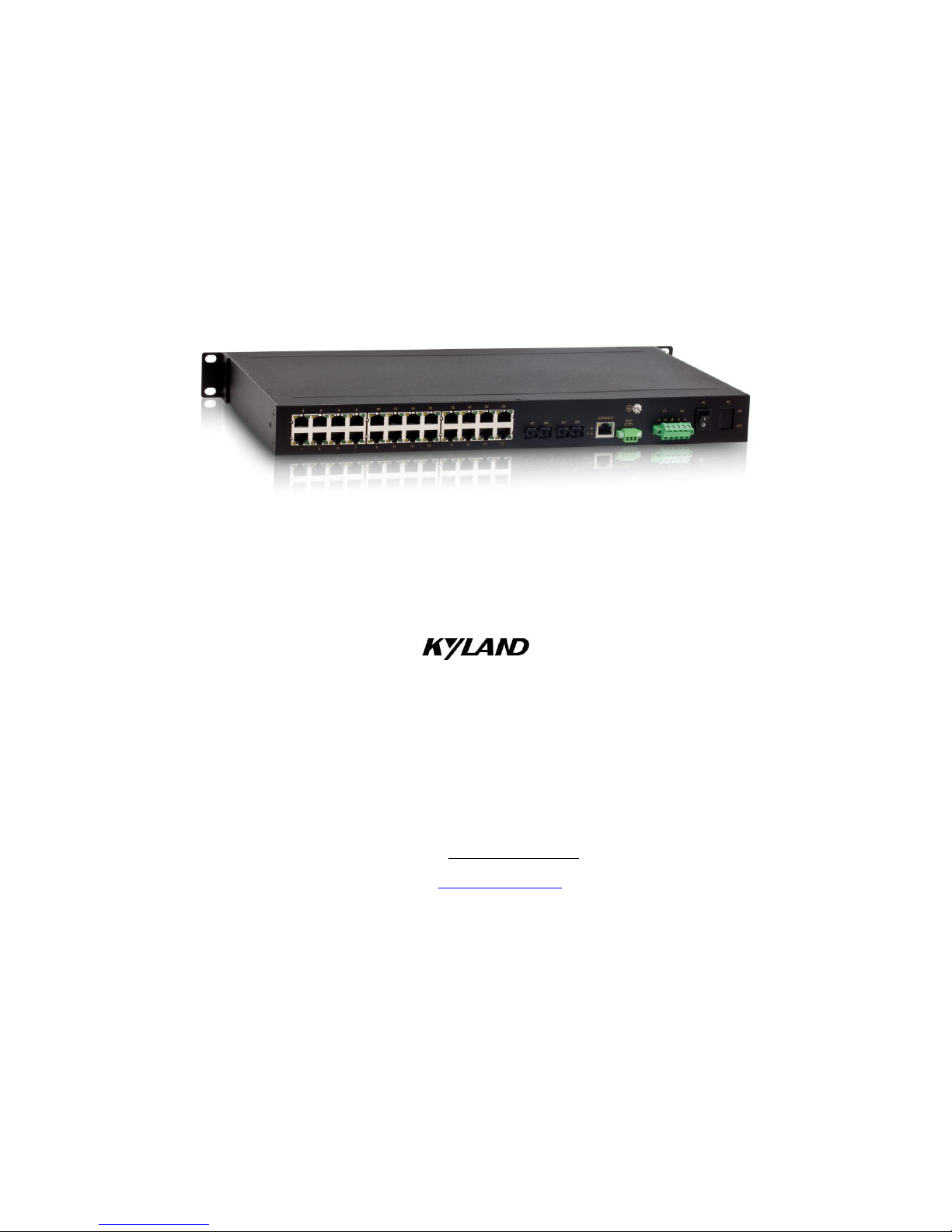
SICOM2024M Industrial Ethernet Switch
Hardware Installation Manual
Kyland Technology Co., Ltd.
Publication Date: Sep. 2013
Version: V4.3
FAX: +86-10-88796678
Website: http://www.kyland.com
E-mail: support@kyland.com

SICOM2024M Industrial Ethernet Switch
Hardware Installation Manual
Disclaimer: Kyland Technology Co., Ltd. tries to keep the content of this manual as accurate and
as updated as possible. This document is not guaranteed to be error-free, and we reserve the right
to amend it without notice to users.
All rights reserved.
No part of this documentation may be excerpted, reproduced, translated, annotated or duplicated,
in any form or by any means without the prior written permission of KYLAND Corporation.
Copyright © 2013 Kyland Technology Co., Ltd.

Notice for Safety Operation
The product performs reliably as long as it is used according to the guidance. Artificial damage or
destruction of the device should be avoided. Before using the device, read this notice carefully for
personal and equipment safety. Please keep the manual for further reference. Kyland is not liable to
any personal or equipment damage caused by violation of this notice.
Do not place the device near water sources or damp areas. Keep the ambient relative humidity
within the range from 5% to 95% (non-condensing).
Do not place the device in an environment with high magnetic field, strong shock, or high
temperature. Keep the working and storage temperatures within the allowed range.
Install and place the device securely and firmly.
Please keep the device clean; if necessary, wipe it with soft cotton cloth.
Do not place any irrelevant materials on the device or cables. Ensure adequate heat dissipation
and tidy cable layout without knots.
Wear antistatic gloves or take other protective measures when operating the device.
Avoid any exposed metal wires because they may be oxidized or electrified.
Install the device in accordance with related national and local regulations.
Before power-on, make sure the power supply is within the allowed range of the device.
Overhigh voltage may damage the device.
Power connectors and other connectors should be firmly interconnected.
Do not plug in or out the power supply with wet hands. When the device is powered on, do not
touch the device or any parts with wet hands.
Before operating a device connected to a power cable, remove all jewelries (such as rings,
bracelets, watches, and necklaces) or any other metal objects, because they may cause
electric shock or burns.
Do not operate the device or connect or disconnect cables during lightning.
Use compatible connectors and cables. If you are not sure, contact our sales or technical
support personnel for confirmation.
Do not disassemble the device by yourself. When an anomaly occurs, contact our sales or
technical support personnel.
If any part is lost, contact our sales or technical support personnel to purchase the substitute.

Do not purchase parts from other channels.
Dispose of the device in accordance with relevant national provisions, preventing
environmental pollution.
In the following cases, please immediately shut down your power supply and contact your Kyland
representative:
Water gets into the equipment.
Equipment damage or shell damage.
Equipment operation or performance has abnormally changed.
The equipment emits odor, smoke or abnormal noise.

I
Contents
1 Product Overview .................................................................................................................... 1
2 Structure and Interface ............................................................................................................ 2
2.1 Front Panel ....................................................................................................................................... 2
2.2 Rear Panel ....................................................................................................................................... 3
3 Mounting .................................................................................................................................. 8
3.1 Dimension Drawing .......................................................................................................................... 8
3.2 Mounting Modes and Steps .............................................................................................................. 8
4 Connection ............................................................................................................................. 11
4.1 10/100Base-T(X) Ethernet Port ...................................................................................................... 11
4.2 100Base-FX Ethernet Port .............................................................................................................. 12
4.3 Console Port ................................................................................................................................... 13
4.4 Grounding....................................................................................................................................... 13
4.5 Power Terminal Block ..................................................................................................................... 14
4.6 Alarm Terminal Block ..................................................................................................................... 16
5 LEDs ...................................................................................................................................... 18
6 Switch Access ........................................................................................................................ 20
6.1 Access through Console Port ......................................................................................................... 20
6.2 Access through Telnet .................................................................................................................... 22
6.3 Access through Web ...................................................................................................................... 22
7 Basic Features and Specifications ......................................................................................... 24

Product Overview
1
1 Product Overview
SICOM2024M includes a series of high-performance industrial Ethernet switches developed by
Kyland particularly for industrial applications. SICOM2024M is applicable to harsh and hazardous
industrial environments due to its high-performance switching engine, solid closed housing, fanless
but heat dissipation-capable single-rib shaped chassis, overcurrent, overvoltage, and EMC
protection for power input, and sound EMC protection of RJ45 ports. The redundant network and
power input support as well as power alarm functions guarantee the reliable operation of the
system.
SICOM2024M provides powerful network management functions. The device can be managed
through CLI, Telnet, Web, and SNMP-based network management software.
SICOM2024M supports 19 inch 1U rack mounting. It provides up to four 10/100Base-T(X) Ethernet
ports and four 100Base-FX Ethernet ports, as listed in the following table.
Table 1 SICOM2024M Models
Model
Port
Power Supply
100Base-FX
Ethernet port
10/100Base-T(X)
Ethernet port
SICOM2024M-4S/M-24T
4
24
220AC/DCW, 220AC/DC, 48DC, 24DC
(single and redundant power supply)
SICOM2024M-2S/M-24T
2
24
SICOM2024M-1S/M-24T
1
24
SICOM2024M-24T
--
24
SICOM2024M-16T
--
16
Note:
We reserve the right to amend the product information listed in this table without notice. To obtain the
latest information, contact our sales or technical support personnel.

Structure and Interface
2
2 Structure and Interface
Caution:
To keep ports clean and ensure switch performance, you are advised to purchase the port dustproof
shield (optional).
2.1 Front Panel
Front Panel (1)
Applicable to: SICOM2024M-4S/M-24T
SICOM2024M-2S/M-24T
SICOM2024M-24T
Figure 1 Front Panel (1)
Table 2 Description of Front Panel (1)
No.
Identifier
Description
(1)
ALARM
Alarm LED
(2)
RUN
Running LED
(3)
PWR1
Power 1 LED
(4)
PWR2
Power 2 LED
(5)
G1-G4: DPX
Speed LEDs for four 100Base-FX Ethernet ports
(6)
G1-G4: LINK
Connection status LEDs for four 100Base-FX Ethernet ports
(7)
1-24: LINK/ACT
Connection status LEDs for twenty-four 10/100Base-T(X) Ethernet ports
(8)
1-24: 10M/100M
Speed LEDs for twenty-four 10/100Base-T(X) Ethernet ports
(9)
CONSOLE
Console port
Front Panel (2)
Applicable to: SICOM2024M-2S/M-24T

Structure and Interface
3
SICOM2024M-1S/M-24T
SICOM2024M-24T
SICOM2024M-16T
Figure 2 Front Panel (2)
Table 3 Description of Front Panel (2)
No.
Identifier
Description
(1)
Run
Running LED
(2)
PWR1
Power 1 LED
(3)
PWR2
Power 2 LED
(4)
A-B: Speed
Speed LEDs for two 100Base-FX Ethernet ports
(5)
A-B: Link/ACT
Connection status LEDs for two 100Base-FX Ethernet ports
(6)
1-24: Link/ACT
Connection status LEDs for twenty-four 10/100Base-T(X) Ethernet ports
(7)
1-24: Speed
Speed LEDs for twenty-four 10/100Base-T(X) Ethernet ports
2.2 Rear Panel
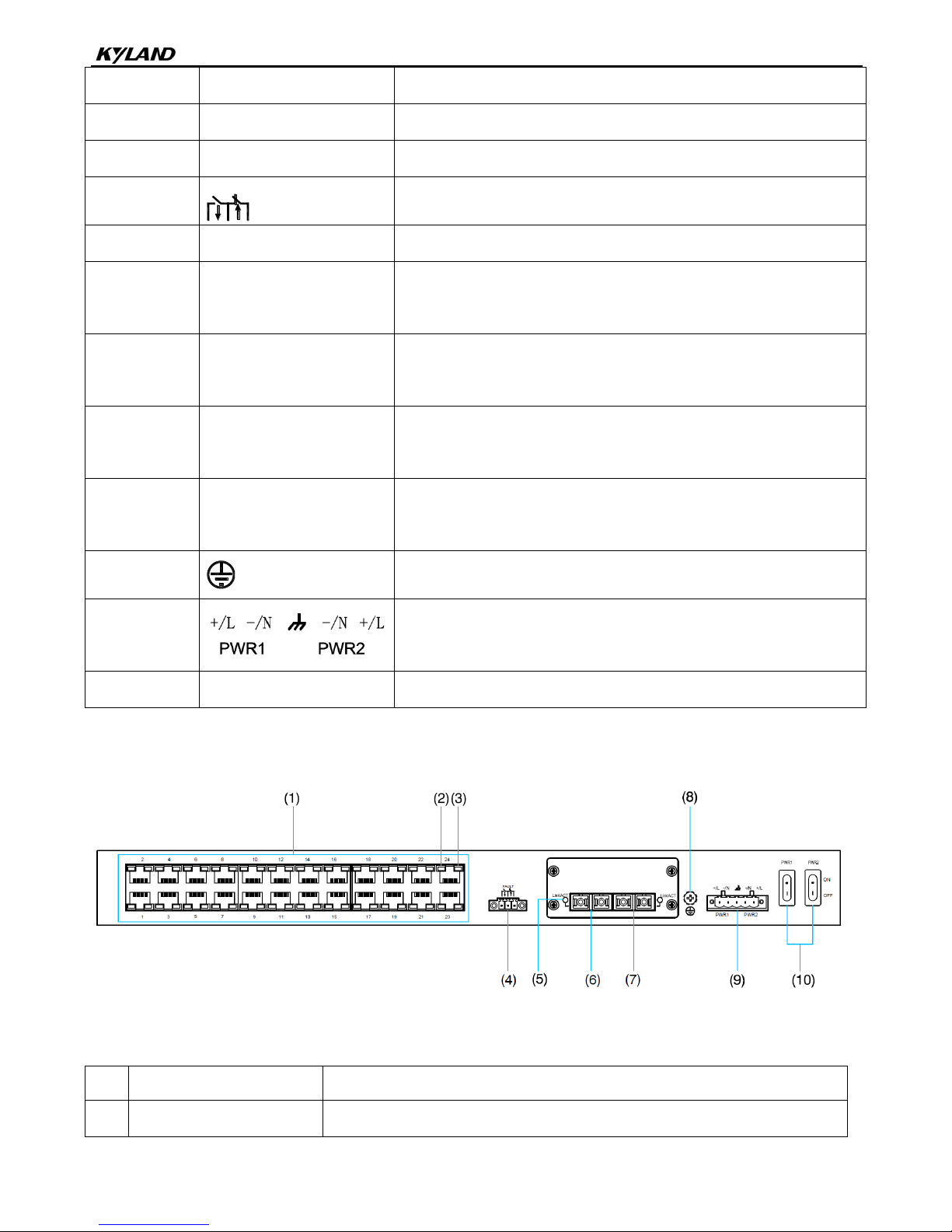
Rear Panel of SICOM2024M-4S/M-24T
Figure 3 Rear Panel of SICOM2024M-4S/M-24T
Table 4 Description of Rear Panel of SICOM2024M-4S/M-24T
No.
Identifier
Description
Structure and Interface
4
(1)
1-24
Twenty-four 10/100Base-T(X) Ethernet ports
(2)
--
10/100Base-T(X) Ethernet port speed LED
(3)
--
10/100Base-T(X) Ethernet port connection status LED
(4)
FAULT
Alarm terminal block
(5)
LINK/ACT
100Base-FX Ethernet port connection status LED
(6)
--
100Base-FX Ethernet port (Its status is indicated by G1 on the front
panel.)
(7)
--
100Base-FX Ethernet port (Its status is indicated by G2 on the front
panel.)
(8)
--
100Base-FX Ethernet port (Its status is indicated by G3 on the front
panel.)
(9)
--
100Base-FX Ethernet port (Its status is indicated by G4 on the front
panel.)
(10)
Grounding screw
(11)
Power terminal block
(12)
PWR1&PWR2: ON/OFF
Switches for Power 1 and Power 2
Rear Panel of SICOM2024M-2S/M-24T (The model involves two types of rear panels. You can
refer to the following descriptions according to your panel type.)
Figure 4 Rear Panel of SICOM2024M-2S/M-24T
Table 5 Description of Rear Panel of SICOM2024M-2S/M-24T
No.
Identifier
Description
(1)
1-24
Twenty-four 10/100Base-T(X) Ethernet ports

Structure and Interface
5
(2)
--
10/100Base-T(X) Ethernet port speed LED
(3)
--
10/100Base-T(X) Ethernet port connection status LED
(4)
FAULT
Alarm terminal block
(5)
Link/ACT
100Base-FX Ethernet port connection status LED
(6)
--
100Base-FX Ethernet port (Its status is indicated by G1 on the front panel.)
(7)
--
100Base-FX Ethernet port (Its status is indicated by G3 on the front panel.)
(8) Grounding screw
(9) Power terminal block
(10)
PWR1&PWR2: ON/OFF
Switches for Power 1 and Power 2
Figure 5 Rear Panel of SICOM2024M-2S/M-24T and SICOM2024M-1S/M-24T
Table 6 Description of Rear Panel of SICOM2024M-2S/M-24T and SICOM2024M-1S/M-24T
No.
Identifier
Description
(1)
1-24
Twenty-four 10/100Base-T(X) Ethernet ports
(2)
--
10/100Base-T(X) Ethernet port speed LED
(3)
--
10/100Base-T(X) Ethernet port connection status LED
(4)
AT AR, BT BR
100Base-FX Ethernet ports
(5)
A, B
100Base-FX Ethernet port connection status LEDs
(6) Grounding screw
(7)
Console
Console port
(8)
Alarm terminal block
(9) Power terminal block

Structure and Interface
6
(10)
P1&P2: ON/OFF
Switches for Power 1 and Power 2
Rear Panel of SICOM2024M-24T (The model involves two types of rear panels. You can refer
to the following descriptions according to your panel type.)
Figure 6 Rear Panel (1) of SICOM2024M-24T
Table 7 Description of Rear Panel (1) of SICOM2024M-24T
No.
Identifier
Description
(1)
1-24
Twenty-four 10/100Base-T(X) Ethernet ports
(2)
--
10/100Base-T(X) Ethernet port speed LED
(3)
--
10/100Base-T(X) Ethernet port connection status LED
(4)
FAULT
Alarm terminal block
(5) Grounding screw
(6)
Power terminal block
(7)
PWR1&PWR2: ON/OFF
Switches for Power 1 and Power 2
Figure 7 Rear Panel (2) of SICOM2024M-24T
Table 8 Description of Rear Panel (2) of SICOM2024M-24T

Structure and Interface
7
No.
Identifier
Description
(1)
1-24
Twenty-four 10/100Base-T(X) Ethernet ports
(2)
--
10/100Base-T(X) Ethernet port speed LED
(3)
--
10/100Base-T(X) Ethernet port connection status LED
(4)
Console
Console port
(5)
Alarm terminal block
(6) Grounding screw
(7) Power terminal block
(8)
P1&P2: ON/OFF
Switches for Power 1 and Power 2
Rear Panel of SICOM2024M-16T
Figure 8 Rear Panel of SICOM2024M-16T
Table 9 Description of Rear Panel of SICOM2024M-16T
No.
Identifier
Description
(1)
1-16
Sixteen 10/100Base-T(X) Ethernet ports
(2)
--
10/100Base-T(X) Ethernet port speed LED
(3)
--
10/100Base-T(X) Ethernet port connection status LED
(4)
Console
Console port
(5) Alarm terminal block
(6) Grounding screw
(7) Power terminal block

Mounting
8
(8)
P1&P2: ON/OFF
Switches for Power 1 and Power 2
3 Mounting
3.1 Dimension Drawing
Figure 9 Dimension Drawing (unit: mm)
Caution:
As part of the heat dissipation system, the switch housing becomes hot during operation. Please use
caution when coming in contact and avoid covering the switch housing when the switch is running.
The figures in this manual are only for reference.
3.2 Mounting Modes and Steps
The series switches support rack mounting by front/rear panel. The following uses mounting by
front panel as an example to describe mounting steps. The steps for mounting by rear panel are

Mounting
9
similar to those for mounting by front panel. Before installation, make sure that the following
requirements are met.
1) Environment: temperature (-40℃ to 85℃), ambient relative humidity (5% to 95%,
non-condensing)
2) Power requirement: The power input is within the voltage range of the switch.
3) Grounding resistance: <5
4) No direct sunlight, distant from heat source and areas with strong electromagnetic interference.
Installing Mounting Brackets
Figure 10 Mounting Bracket
You can select the screw holes for front or rear panel mounting to install the mounting brackets. If
there are screws inserted in the screw holes, remove the screws and keep them for future use.
As shown in the following figure, use three screws to secure two mounting brackets to the switch
respectively.
Figure 11 Installing Mounting Brackets
Mounting
Step 1: Select the mounting position for the switch and guarantee adequate space and heat

Mounting
10
dissipation for it (dimensions: 440mm×44mm×245mm).
Step 2: Move the switch in direction 1 until the screw holes for securing the mounting brackets to
rack posts are in alignment with the corresponding holes in the rack posts. Then use four
screws and supporting captive nuts to secure the mounting brackets to the rack posts.
Figure 12 Mounting
Dismounting
Step 1: Remove the four screws and supporting captive nuts securing the mounting brackets to the
rack posts.
Step 2: Remove the switch from the rack posts. Then unscrew the mounting brackets to complete
dismounting.

Connection
11
4 Connection
4.1 10/100Base-T(X) Ethernet Port
10/100Base-T(X) Ethernet port is equipped with RJ45 connector. The port is self-adaptive. It can
automatically configure itself to work in 10M or 100M state, full or half duplex mode. The port can
also adapt to MDI or MDI-X connection automatically. You can connect the port to a terminal or
network device with a straight-through or cross-over cable.
Pin Definition
The following figure shows the pin numbers of the RJ45 port.
8 7 6 5 4 3 2 1
Figure 13 RJ45 Port
The following table lists the pin definitions of the 10/100Base-T(X) RJ45 port.
Table 10 Pin Definitions of 10/100Base-T(X) RJ45 Port
Pin
MDI-X Signal
MDI Signal
1
Receive Data+ (RD+)
Transmit Data+ (TD+)
2
Receive Data- (RD-)
Transmit Data- (TD-)
3
Transmit Data+ (TD+)
Receive Data+ (RD+)
6
Transmit Data- (TD-)
Receive Data- (RD-)
4, 5, 7, 8
Unused
Unused
Note:
"+" and "-" indicate level polarities.
Wiring Sequence

Connection
12
Figure 14 Connection Using Straight-through/Cross-over Cable
Note:
The color of the cable for RJ45 connector meets the 568B standard: 1-orange and white, 2-orange,
3-green and white, 4-blue, 5-blue and white, 6-green, 7-brown and white, and 8-brown.
4.2 100Base-FX Ethernet Port
100Base-FX Ethernet port is equipped with FC/ST/SC connector, and each port consists of TX
(transmit) port and RX (receive) port. To enable data transmission between Device A and Device B,
connect the TX port of Device A to the RX port of Device B, and the RX port of Device A to the TX
port of Device B. The following uses an SC port as an example. The wiring sequence of an ST/FC
port is the same with that of the SC port.
Figure 15 Connection of 100Base-FX Ethernet Port
Caution:
The device uses laser to transmit signals in fibers. The laser meets the requirements of level 1 laser
products. Routine operation is not harmful to your eyes, but do not look directly at the fiber port when the

Connection
13
device is powered on.
4.3 Console Port
Connect the 9-pin serial port of a PC to the console port of the switch with an RJ45-DB9 console
cable. Then you can configure, maintain, and manage the switch by running the Hyper Terminal in
the Windows OS of the computer.
Figure 16 Console Port
RJ45-DB9 Console Cable
One end of an RJ45-DB9 console cable is crimped RJ45 connector to be inserted into the console
port of the switch, and the other end is the DB9 connector to be inserted into the 9-pin serial port of
a PC.
Figure 17 Wiring Sequence of DB9-RJ45 Console Cable
Table 11 Pin Definitions of DB9-RJ45 Console Cable
DB9 Pin
RJ45 Pin
Signal
Description
2 3 RXD
Receive data
3 2 TXD
Transmit data
5 5 GND
Grounding
4.4 Grounding
Grounding protects the switch from lightning and interference. Therefore, you must ground the
Connection
14
switch properly. You need to ground the switch before it is powered on and disconnect the
grounding cable after the switch is powered off.
The switch provides a grounding screw on the rear panel for chassis grounding. After crimping one
end of the grounding cable to a cold pressed terminal, secure the end to the grounding screw and
connect the other end to the earth firmly.
Figure 18 Grounding
Note:
Cross-sectional area of the chassis grounding cable>2.5mm2; grounding resistance<5.
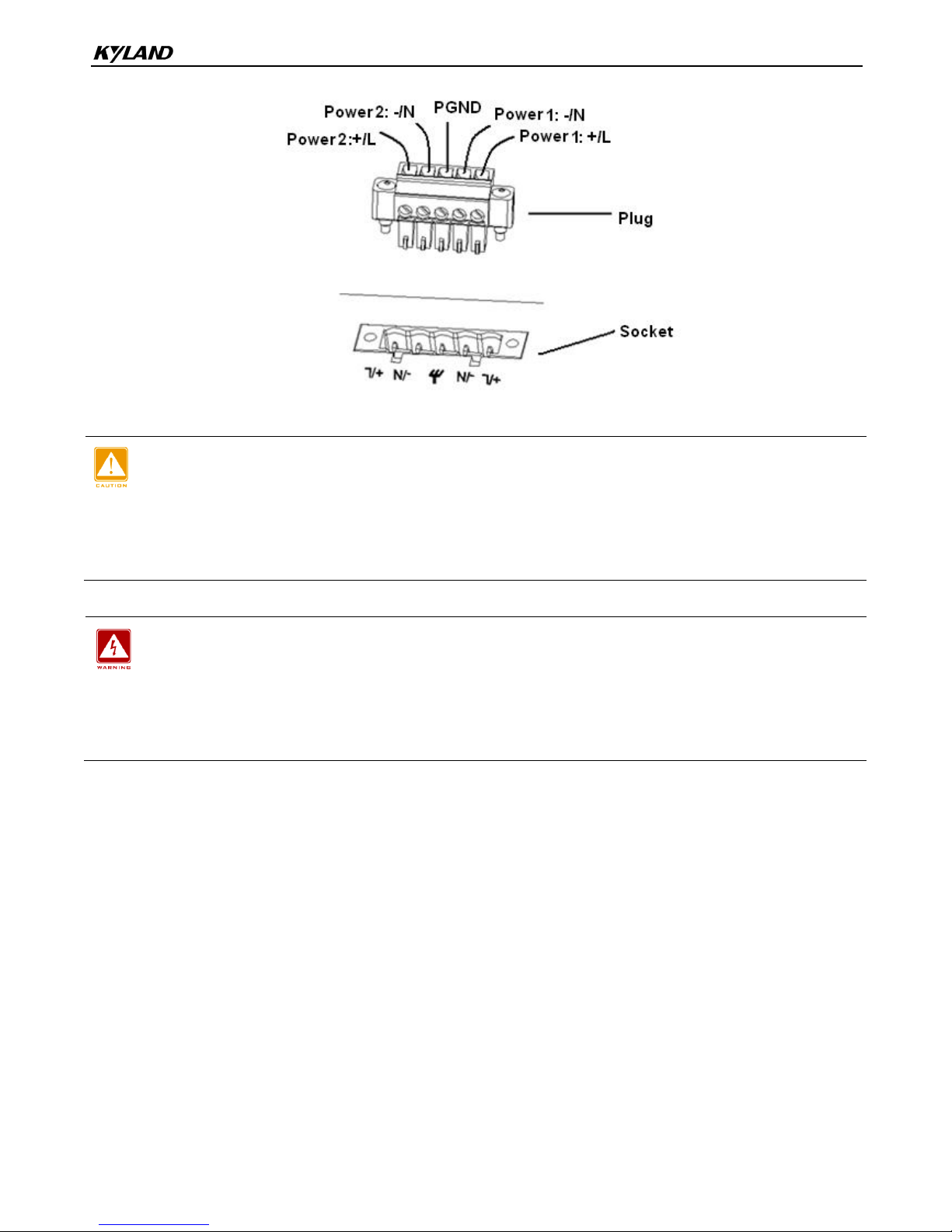
4.5 Power Terminal Block
There is a power terminal block on the rear panel of the device. You need to connect the power
wires to the terminal block to provide power for the device. The device supports both single and
redundant power supply with 5-pin 5.08mm-spacing plug-in terminal block. When the redundant
power supply is used and one power input is faulty, the device can continue operating properly,
thereby improving network reliability.
Note:
0.75mm2<Cross-sectional area of the power wire<2.5mm2; grounding resistance<5.
5-Pin 5.08mm-Spacing Plug-in Terminal Block
The following figure shows the 5-pin 5.08mm-spacing plug-in terminal block.
Figure 19 5-Pin 5.08mm-Spacing Plug-in Terminal Block (socket)

Connection
15
The following table lists the pin definitions of the 5-pin 5.08mm-spacing plug-in terminal block.
Table 12 Pin Definitions of 5-Pin 5.08mm-Spacing Plug-in Terminal Block
No.
DC Definition
AC Definition
1
Power 1: +
Power 1: L
2
Power 1: -
Power 1: N
3
PGND
PGND
4
Power 2: -
Power 2: N
5
Power 2: +
Power 2: L
Caution:
For single power supply, only pins 1, 2, and 3 of the terminal block can be connected. Do not use pins 4
and 5.
Wiring and Mounting
Step 1: Ground the device properly according to section 4.4.
Step 2: Remove the power terminal block from the device.
Step 3: Insert the power wires into the power terminal block according to Table 12 and secure the
wires.
Step 4: Insert the terminal block with the connected wires into the terminal block socket on the
device.
Step 5: Connect the other end of the power wires to the external power supply system according to
the power supply requirements of the device. Turn on the switch for the connected power
(power 1, power 2, or both). View the status of the power LEDs on the front panel. If the
LEDs are on, the power is connected properly.
Connection
16
Figure 20 Connection of 5-Pin 5.08mm-Spacing Plug-in Terminal Block
Caution:
The switch supports 220AC/DCW, 220AC/DC, 48DC, and 24DC power input. Before connecting the
device to power supply, make sure that the power input meets the power requirement. If connected to an
incorrect power input, the device may be damaged.
Warning:
Do not touch any exposed conducting wire, terminal, or component with a voltage warning sign,
because it may cause damage to humans.
Do not remove any part or plug in or out any connector when the device is powered on.
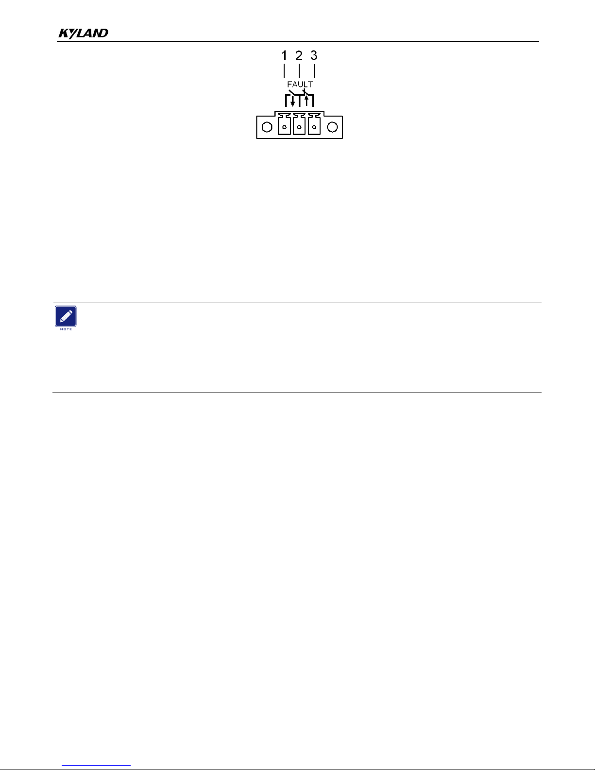
4.6 Alarm Terminal Block
The device provides an alarm terminal block on the rear panel for alarm output. When the switch
works properly, the normally-open contacts of the alarm relay are closed and the normally-closed
contacts are open; when an alarm occurs, the normally-open contacts are open and the
normally-closed contacts are closed. The alarm is outputted through a 3-pin 3.81mm-spacing
plug-in terminal block.
Connection
17
Figure 21 Alarm Terminal Block (socket)
Electrical parameters of the relay:
Max Switch Voltage: 250VAC/220VDC;
Max Switch Current: 2A
Max Switching Power: 60W
Dielectric Strength: 2KV
Note:
Pin 1 and pin 2 are normally-open contacts; pin 2 and pin 3 are normally-closed contacts. When the
switch works properly, pin 1 and pin 2 are closed, pin 2 and pin 3 are open; when an alarm occurs, pin 1
and pin 2 are open; pin 2 and pin 3 are closed.
Wiring and Mounting
Step 1: Remove the alarm terminal block from the switch.
Step 2: Secure the three wires for alarm into the alarm terminal block in the required sequence.
Step 3: Insert the alarm terminal block into its socket.

LEDs
18
5 LEDs
Table 13 Front Panel LEDs
LED
State
Description
Power 1 LED
On
Power 1 is connected and operates properly.
Off
Power 1 is not connected or operates abnormally.
Power 2 LED
On
Power 2 is connected and operates properly.
Off
Power 2 is not connected or operates abnormally.
Running LED
Blinking
The CPU operates properly.
On
The CPU operates abnormally.
Off
The CPU operates abnormally or does not start up;
the device is starting up.
Alarm LED
On
An alarm occurs.
Off
No alarm occurs.
100Base-FX Ethernet port speed
LED
On
100M working state (100Base-FX)
Off
No connection
100Base-FX Ethernet port
connection status LED
On
Effective port connection
Blinking
Ongoing network activities
Off
No effective port connection
10/100Base-T(X) Ethernet port
speed LED
On
100M working state (100Base-TX)
Off
10M working state (10Base-T) or no connection
10/100Base-T(X) Ethernet port
connection status LED
On
Effective port connection
Blinking
Ongoing network activities
Off
No effective port connection
Table 14 Rear Panel LEDs
LED
State
Description

LEDs
19
10/100Base-T(X) Ethernet port
speed LED (yellow)
On
100M working state (100Base-TX)
Off
10M working state (10Base-T) or no connection
10/100Base-T(X) Ethernet port
connection status LED (green)
On
Effective port connection
Blinking
Ongoing network activities
Off
No effective port connection
100Base-FX Ethernet port
connection status LED
On
Effective port connection
Blinking
Ongoing network activities
Off
No effective port connection

Switch Access
20
6 Switch Access
You can access the switch in any of the following ways:
6.1 Access through Console Port
Step 1: Connect the console port of the switch to the 9-pin serial port of a PC with the delivered
RJ45-DB9 console cable.
Step 2: Open the Hyper Terminal in the Windows OS. On the desktop, click Start → All Programs →
Accessories → Communications → Hyper Terminal.
Step 3: Create a connection "Switch", as shown in the following figure.
Figure 22 Creating a Connection
Step 4: Connect the communication port in use, as shown in the following figure.

Switch Access
21
Figure 23 Selecting a Serial Port
Note:
To confirm the communication port in use, right-click [My Computer] and select [Property]. Click
[Hardware] → [Device Manager] → [Port] to view the communication port.
Step 5: Set port parameters (Bits per second: 9600, Data bits: 8, Parity: None, Stop bits: 1, and
Flow control: None), as shown in the following figure.

Switch Access
22
Figure 24 Setting Port Parameters
Step 6: Click OK to enter the switch CLI. Then you can run the following commands to perform
operations.
Table 15 CLI Commands
View
Command
Description
User view
SWITCH>enable
Enter the management view.
Management view
SWITCH#show interface
Query the current IP address of the switch.
Management view
SWITCH#show version
Query the version of the switch.
Management view
SWITCH#reboot
Restart the switch.
Management view
SWITCH#load default
Restore the factory default settings (excluding the IP
address).
Management view
SWITCH#config terminal
Enter the configuration view.
6.2 Access through Telnet
Step 1: Connect the network port of the PC to the RJ45 port of the switch with an RJ45-RJ45 cable.
Step 2: Enter "telnet IP address" in the Run dialog box. For example, if the IP address of the switch
is 192.168.0.2 (default IP address of a Kyland switch), enter "telnet 192.168.0.2" in the
dialog box.
Figure 25 Access through Telnet
Step 3: Click OK. The Telnet CLI is displayed. Then you can enter commands (as listed in Table 15)
to perform operations.
6.3 Access through Web
Step 1: Connect the network port of the PC to the RJ45 port of the switch with an RJ45-RJ45 cable.
Step 2: Enter the IP address of the switch in the address box of the browser. The user login

Switch Access
23
interface is displayed. You can log in to the Web UI by default user name "admin" and
password "123".
Note:
IE8.0 or a later version is recommended.
For details about how to access the switch and other operations, refer to the Web operation manual in
the delivered CD.

Basic Features and Specifications
24
7 Basic Features and Specifications
Power Requirements
Power Identifier
Rated Voltage Range
Maximum Voltage Range
24DC
24VDC
18-36VDC
48DC
48VDC
36-72VDC
220AC/DC
100-240VAC, 50/60Hz; 220VDC
85-264VAC/120-300VDC
220AC/DCW
100-240VAC, 50/60Hz; 110-220VDC
85-264VAC/77-300VDC
Terminal block
5-pin 5.08mm-spacing plug-in terminal block
Rated Power Consumption
Rated power consumption
<16.8W
Physical Characteristics
Housing
Metal, fanless
Installation
19 inch 1U rack mounting
Dimensions (W×H×D)
440mm×44mm×245mm
(excluding connectors and mounting brackets)
Weight
2.5Kg
Environmental Limits
Operating temperature
-40℃~+85℃
Storage temperature
-40℃~+85℃
Ambient relative humidity
5%~95% (non-condensing)
MTBF
MTBF
338,566 hours
Warranty
Warranty
5 years
For more information about KYLAND products, please visit our website: http://www.kyland.com
 Loading...