


KIEN2032 Industrial Ethernet Switch
User’s Manual
KYLAND Telecom Technology Co., Ltd.

KIEN2032 Industrial Ethernet Switch
User’s Manual
Copyright © 2005 KYLAND Telecom Technology CO., LTD.
All rights reserved.
No part of this documentation may be excerpted, reproduced, translated, annotated or
duplicated, in any form or by any means without the prior written permission of KYLAND
Corporation.
Publisher: KYLAND Telecom Technology CO., LTD
Address: P.O.Box 100096, 085, Beijing, China
Website: http://www.kyland.cn
Postcode: 100096
Tel: (+86 10)82900770
Fax: (+86 10)82900780
E-mail:marketing @ kyland. com. cn
Version: V1, Dec. 2005
No.: e6t04050901

Preface
KIEN2032 is the high-performance network management Ethernet switch developed
by KYLAND for industrial application. It is integrated optical communication
equipment, which integrates with Ethernet access and serial data transmission. Its
high-performance switching engine, firmness and closed case design, high-effective
ribbed casing for heat removal without fan, over-current, over-voltage and EMC
protection for power supply input terminal, excellent EMC protection performance for
the Ethernet RJ45 port, RS232 and RS485 port enable the KIEN2032 to adapt the
tough and dangerous industrial environment. The redundant function of the optical
fiber network, independent network management channel for the whole network and
powerful real time network management system for the whole network provide
strongly guarantee for the reliable operation of the system.
The KIEN2032 Industrial Ethernet Switch User’s Manual mainly introduces the
technical principle, performance index, installation and commission of the KIEN2032
industrial Ethernet switch, and provides the reference for users to commence, expand
and routine maintain the system. At the same time, it applies to the user training and
learning for related technical personnel, so it is the practical teaching material for mass
users to learn about the KIEN2032 industrial Ethernet switch.
This document mainly contains following contents:
Chapter1 Overview and System Features
Chapter2 Performance Index and Service Function
Chapter3 Hardware Architecture
Chapter4 Installation Procedure
Chapter5 Configuration and Application Method
Chapter6 Field Test Method
Chapter6 Networking Modes and System Configuration
Appendix A Twisted-pair and Pin Assignment Rules
Appendix B Type and Specification of Cable
Appendix C Abbreviation

This document is used together with the Kyvision Industrial Ethernet Switch Dedicated
Network Management User’s Manual.
Statement: For continuous update and perfection of the product and
technology, the contents of this material may not be consistent with the
actual product, please contact with us about related contents. If it is
necessary for you to query the latest information on the product, please
query our cooperation Website or contact with your local service
representative directly.

Safety Notices
This product can provide excellent and reliable performance within its design scope.
However, it needs to avoid the damage or destroy by human reasons.
Read this Manual thoroughly and keep it well for future reference.
Do not place the equipment next to the source of water and the damp place.
Do not place anything on the power cable. Please place it somewhere that can not
be reached.
In order to avoid fire, do not tie or pack the cable.
The connector of the power supply and other equipment connection should be
connected firmly and regularly checked.
Under following conditions, please power off and contact with our company
immediately.
1. Water into equipment;
2. Equipment is broken or the crust is cracked.
3. The equipment works abnormally or the performance provided has changed
completely.
4. The equipment gives off odor, smoke or noise.
Pay attention to the cleanness of the fiber socket and jack. When the equipment
operates, do not watch the end-face of the fiber directly.
Pay attention to the cleanness of the equipment and clean it with soft cotton cloth
if necessary.
Do not repair the equipment by yourself unless it is definitely indicated in this
manual.
Description of Warning Mark:
This manual uses two kinds of obvious warning marks to prompt users that more
attention should be paid during operation. The meanings of these marks as follows:
incorrect operation will cause the switch to be damaged seriously or it will
cause body injury for the operator.
Caution, Note, Warning and Dangerous: Prompt where more attention
should be paid.
Warning: The comment after this mark should be paid more attention, the

Contents
Chapter1 System Overview..........................................................................................................................1
1.1 Product Overview ..........................................................................................................................1
1.2 Features..........................................................................................................................................2
1.3 Packing List and Unpacking Check...............................................................................................3
Chapter2 Performance Index.......................................................................................................................5
2.1 System Index .......................................................................................................................................5
2.2Service interface...................................................................................................................................6
2.3 Service Functions...........................................................................................................................7
Chapter3 Hardware Structure.....................................................................................................................9
3.1 System structure.............................................................................................................................9
3.2 Switch Structure...........................................................................................................................10
3.2.1 Case.......................................................................................................................................10
3.2.2 Front Panel............................................................................................................................ 11
3.2.3 Top Panel............................................................................................................................... 15
3.2.4 Bottom Panel.........................................................................................................................18
Chapter 4 Hardware Installation............................................................................................................21
4.1 Installation Requirement..............................................................................................................21
4.2 Installation of Main Machine.......................................................................................................21
4.2.1 Rail Installation.....................................................................................................................21
4.2.2 Wall-mounted Installation.....................................................................................................23
4.3 Cable Connection.........................................................................................................................27
4.4 Optical Fiber Connection.............................................................................................................27
4.5 Cable Layout................................................................................................................................ 29
Chapter 5 Configuration and Application of Data Port........................................................................31
5.1 Configuration of Data Port...........................................................................................................31
5.1.1 Logon Console Network Management .................................................................................31
5.1.2 Console Network Management............................................................................................. 33
-i-

5.1.3 WEB Network Management..................................................................................................41
5.2 Application of Data Ports.............................................................................................................44
5.2.1 As TCP Server .......................................................................................................................44
5.2.2 As TCP Client........................................................................................................................45
5.2.3 UDP Method..........................................................................................................................45
Chapter 6 Testing Methods.......................................................................................................................47
6.1 Self Testing...................................................................................................................................47
6.2 Testing of Ethernet Ports ..............................................................................................................47
6.3 Testing of Fiber Ports.........................................................................................................................48
6.4 Data Ports Test..............................................................................................................................49
Chapter 7 Networking Modes and System Configuration.....................................................................51
7.1 Networking Modes .......................................................................................................................51
7.2 System Configuration...................................................................................................................52
Appendix A Twisted-pair and Pin Distribution.........................................................................................55
Appendix B Type and Specification of Cable............................................................................................57
Appendix C Glossary...................................................................................................................................59
-ii-

Chapter1 System Overview
1.1 Product Overview
KIEN2032 is the high-performance network management Ethernet switch developed
by KYLAND for industrial application. It is the integrated optical communication
equipment which integrates with Ethernet access and serial data transmission. Its
high-performance switching engine, firmness and closed case design, high-effective
ribbed casing for heat removal without fan, over-current, over-voltage and EMC
protection for power supply input terminal, excellent EMC protection performance for
the Ethernet RJ45 port, RS232 and RS485 port enable the KIEN2032 to adapt the
tough and dangerous industrial environment. The redundant function of the optical
fiber network, independent network management channel for the whole network and
powerful real time network management system for the whole network And it can
strongly guarantee the reliable operation of the system.
The KIEN2032 industrial Ethernet switch can provide two installation methods such as
DIN rail and wall-mounted. The front panel presents two pair of 100Base-FX single
mode or multi-mode optical fiber interface with uplink redundancy. It can take
advantage of the uplink redundant optical fiber interface to form the optical fiber
redundant ring network, so the recovery time for the ring network redundancy is less
than 300ms when the system failure occurs. There are three 10Base-T/100Base-TX
Ethernet RJ45 ports. Each RJ45 port can provide the adaptive function and can be
configured to 10Base-T or 100Base-TX status automatically and the full duplex and half
duplex operation mode. Furthermore, it can connect MDI/MDI-X automatically. 2
channel of RS232 and 2 channels of RS485 data interface which can implement the
point to point and point to multi-point communication on the network, to implement
the remote online of the serial port equipment readily.
-1-

KIEN2032 Industrial Ethernet Switch User's Manual
1.2 Features
High-performance Industrial Ethernet Switch
1. 10/100Base-T/TX Ethernet ports, auto-sensing, full/half duplex, Auto MDI/MDI-X
connection
2. 100Base-FX fiber ports, single mode/multimode, full duplex
3. High-speed redundant optical fiber ring (recovery time < 300ms)
4. VLAN to take control of broadcast domain and segment flow
5. Broadcast storm control
Powerful Management Function
1. Integral management platform for the entire network based on RS232 standard.
The management system is immune against the attack of virus or hacker since
the management channel is independent to service channel.
Industrial Power
2. Special-designed management software for upper PC realizes the
auto-configuration of IP address for networking devices and auto-scan/spanning
of network topology.
3. Individual naming for each devices in the network.
4. Setting and query for VLAN.
5. Setting and query for alarm of power and ports.
6. Setting and query for port working mode, prioritization, and rate
1. Industrial power input of DC24V(DC18V~36V).
2. Reliable protection for EMC and against over-current/over-voltage.
-2-

Chapter1 System Overview
Multiple Serial Data Transmission
1. 2 x RS232, 2 x RS485 or 1 x RS232 and 1 x RS485.
2. Supports TCP and UDP and distribute the data from IP level according to TCP
and UDP user-targeted ports.
3. Open SOCKET mode for store data.
4. Point-to-point or multipoint-to-multipoint.
Industrial Design
1. Solid IP40 housing
2. Operation at -35℃ to +75℃
3. Air humidity 10% to 95%
4. Easy DIN-Rail mounting
1.3 Packing List and Unpacking Check
1. Packing List
The packing box contains following contents:
KIEN2032 1
3-pin DC Power Supply Terminal 1
8-pin Data Interface Terminal 1
KIEN2032 Industrial Ethernet Switch User’s Manual 1
Kyvision Industrial Ethernet Switch Dedicated Network Management User’s
accompanying with 1 software CD 1
Customer Service Manual 1
Ф3 Grounding Cool Terminal, M3*8 Grounding Screw 1 set
-3-

KIEN2032 Industrial Ethernet Switch User's Manual
2. Unpacking Check
Place the box smoothly before it is opened and note direction of the packing box
and ensure its face upward to prevent dropping of the switch after unpacking. Avoid
the KIEN2032 drops after the box is opened. If the hard material is used to open
this box, the hard material should not enter the case body too much to prevent the
internal equipment damaged.
Check the quantity of KIEN2032 according to the packaging check list (including
the KIEN2032 host, the equipment parts, user’s manual and customer service
manual) and check the appearance quality of KIEN2032.
Warning:
The equipment is built in precision device, please note to gentile take and place it to
avoid drastic vibration which will have an effect on the performance of the equipment.
-4-

Chapter2 Performance Index
2.1 System Index
The system performance index of the KIEN2032 industrial Ethernet switch is shown as
table 2-1.
Quantity of RJ45 port 3 10Base-T/100Base-TX
Quantity of uplink redundant
fiber port
Number of serial data
interfaces
System parameters
Ethernet port
Data port
Fiber port
Table2-1 System Index
System Index KIEN2032
2 100Base-FX-SM/MM
2 RS232s, 1 RS485 or 1 RS232 and 2 RS485s
Support standard: IEEE802.3, IEEE 802.3x, IEEE 802.3u, IEEE
802.1p and IEEE 802.1Q
Storage and forward rate: 148810 pps
Maximum filtering rate: 148810 pps
MAC address table: 4K
Switch method: storage and forward
System switching bandwidth: 4.8G
Maximum number of VLANs: 16
EMC interference: EN55022
EMC immunity: EN50082-2
Physical interface: RJ-45 with shield
RJ-45 port: 10Base -T/100Base-TX can support the
self-negotiation function.
Interface standard: Comply with IEEE802.3 standard.
Transmission distance: less than 100m
Physical interface: 3.81 phoenix wiring terminal
BER for data transmission: ≤10
Asynchronous rate: 0~115.2Kbps (adaptive)
Support both TCP/IP and UDP/IP protocol
RS-485 interface: Can connect to 32-128 nodes with
communication distance 120m.
Electrical characteristics: comply with 3-wire RS232- and
2-wire RS485-related standard.
Light Transmission Power: >-13dbm(SM) >-20dbm(MM)
Light Receiving Sensitivity: <-28dbm(SM) <-35dbm(MM)
Wavelength: 1310nm(SM) 1550nm(SM) 1310 nm(MM)
-10
-5-

KIEN2032 Industrial Ethernet Switch User's Manual
Transmission distance: 20~80Km(SM) <2Km(MM)
Connector type: SC/FC
Transmission rate: 125Mbps
Physical interface: RJ-45 with shield
CONSOLE interface
Power supply
Mechanical parameters
Ambient conditions
Interface standard: Comply with IEEE802.3 standard (3-wire).
Interface rate: 19200bps
Input voltage: DC24V (DC 18V~36V)
Input power consumption: <6W
Over-current protection: Built-in
Physical dimension (H * W * D): 142 ㎜55.4 ㎜120.5 ㎜ (don’t
include DIN rail and wall-mounted assemble dimension)
Installation method: DIN rail and wall-mounted method
Heat removal method: Ribbed aluminum casing heat dissipation
without fan.
Outgoing wire method: Service\power supply lead from front
and the network management lead from upper.
Crust protection: IP40
Weight: 1kg
Operation temperature: -35~75
Storage temperature: -45~85
Humidity: 10%~95% (non-condensing)
2.2Service interface
1. Three 10Base-T/100Base-TX Ethernet RJ4 ports, each of which presents the
adaptive function. Can be adaptive of 10/100M and operate in half duplex/full
duplex mode automatically, and support MDI/MDI-X auto-connection. The
transmission distance is less than 100m.
2. 2 pair of 100Base-FX single-mode or multi-mode fiber ports, each of which
provides the throughput up to 100Mbps and is forced to be in the 100M full
duplex working mode. Support optical route redundant technology and the
redundant recovery time is less than 300ms.
3. Comply with the IEEE802.3/802.3U/802.3X.
4. The meaning of RJ45 ports is: Yellow light – Indication for port rate.ON:
100M,;OFF: 10M. Green Light – Indication for connection status: ON: effective
connection network; BLINKING: network active; OFF: connectionless.
5. 2 0~115.2Kbps adaptive serial data with two types of interfaces such as RS232
and RS485.
-6-

Chapter2 Performance Index
2.3 Service Functions
Connection of Serial Data
In KIEN2032, a serial port server is embedded to make serial data into Ethernet packets and
realize Ethernet switching and transmitting for serial data.
Independent Management of Serial Port Server
The embedded serial port server of KIEN2032 owns its independent IP address, and the
relevant parameters of server and its ports can be managed, queried, and set through remote
Telnet, WEB and serial port mode.
100Mbit/s Optical Fiber Redundancy
It is critical for network to re-configure immediately once disconnection occurs in the
industrial fields. Accordingly, KIEN2032 comes with DT-Ring, which is developed by
KYLAND, and offers 2 redundant fiber ports to realize the redundant ring network. The
system will be able to re-configure within 300ms after cable fault.
Configuration and Management
At KIEN2032, the settings, queries and management can be realized for the whole switch
or network system through CONSOLE interface.
LED Indicating
The LEDs indicate the port status correctly including transmission rate, link status and
system status.
VLAN
The network can be divided into several VLANs according to ports, through which the
users in one VLAN can communicate each other. The VLAN of KIEN2032 conforms to
IEEE802.1Q and can realize the communication within one VLAN of different switches.
KIEN2032 supports up to sixteen VLANs based on IEEE802.1Q.
802.1p Prioritization
KIEN2032 conforms to 802.1p, which is used the most widely in LAN environment. The
end-users of KIEN2032 can make use of this function to configure the port-based
prioritization when 802.1p is not supported at user’s end and different priority is necessary
for different ports’ services. Only the data package without Prioritization in the Packet in
the ports can be affected by this function. Each port of KIEN2032 supports 2 levels (high,
-7-

KIEN2032 Industrial Ethernet Switch User's Manual
low) prioritization.
Layer-2 Switching
Switches work in two ways: Cut-Through and Store-and-Forward. In Cut-Through, a
data packet is immediately relayed further after detecting the target address; in
Store-and-Forward, a data packet is first read-in completely and checked for errors
before the switch relays the same. KIEN2032 employs Store-and-Forward that is a
switching mode widely used.
Broadcast Storm Control
Broadcast storm is the ceaseless transfer of broadcast frame or multicast frame in
bridge, which is caused by loop and will waste much bandwidth. The purpose of
broadcast storm control is to optimize the performance of switch network. KIEN2032
supports the broadcast storm based on percentage. With the control percentage, the
broadcast flow of KIEN2032 will be monitored and controlled effectively. The switch
will filter out the over flow and ensure the flow percentage is normal once the
bandwidth of broadcast flow exceed the limit.
Alarming Function
KIEN2032 offers the alarming functions for port link and network. Through
management software, all the alarming functions can be configured functionally. The
alarming information is shown on management interface.
Setting for Working Mode of Port
KIEN2032 is able to set the working mode of all ports through management: full/half
duplex, auto-sensing, enforced full/half duplex, enforced 10M/100M etc.
Setting for Port Rate
KIEN2032 is able to set the rate of all ports through management as any integer
multiple of 32kbps.
-8-

Chapter3 Hardware Structure
3.1 System structure
The hardware architecture of the KIEN2032 industrial Ethernet switch is shown as
Figure .3-1.
CONSO
LE
口
Switching
Network
Controller
Serial Data Server
Power
Power Port
EMC
protections
Port 4
Port 8
Figure .3-1 Hardware Structure
Ethernet Ports
1.3.6
DATA1 DATA2
The system hardware mainly consists of following parts:
1. The switching network controller adopts the high performance ASIC chip
technology to provide the layer2 line rate forward for the data packet.
2. The serial data server adopts the high performance ASIC chip technology to
provide the conversion of TCP/IP protocol packet for the serial data.
3. Two channels of data can provide the RS232 and RS485 interface.
4. The optical fiber interface adopts the optical receiving and transmitting integrated
module to provide stable performance.
5. The power supply adopts the industrial-level one which can provide the
over-current, over-voltage and EMC protection.
6. All Ethernet interfaces, data interfaces and CONSOLE interfaces can provide the
EMC protection.
-9-

KIEN2032 Industrial Ethernet Switch User's Manual
3.2 Switch Structure
3.2.1 Case
The case of the KIEN2032 is a compact wall-mounted or DIN rail structure. The whole
equipment adopts the hexahedral full closed structure with the protection level up to
IP40. The left and right side ribbed plate of the case is made of aluminum and is a part
of the whole equipment head dissipation system. The ribbed structure can increase the
heat dissipation area double. The heat produced by the whole equipment can be
removed to the environment effectively by taking advantages of the ribbed caing in the
radiation and convection way, by which to greatly improve the high
temperature-resistance performance of the equipment. It spurns the traditional fan for
heating removal, and reduces the power consumption of the whole equipment as well
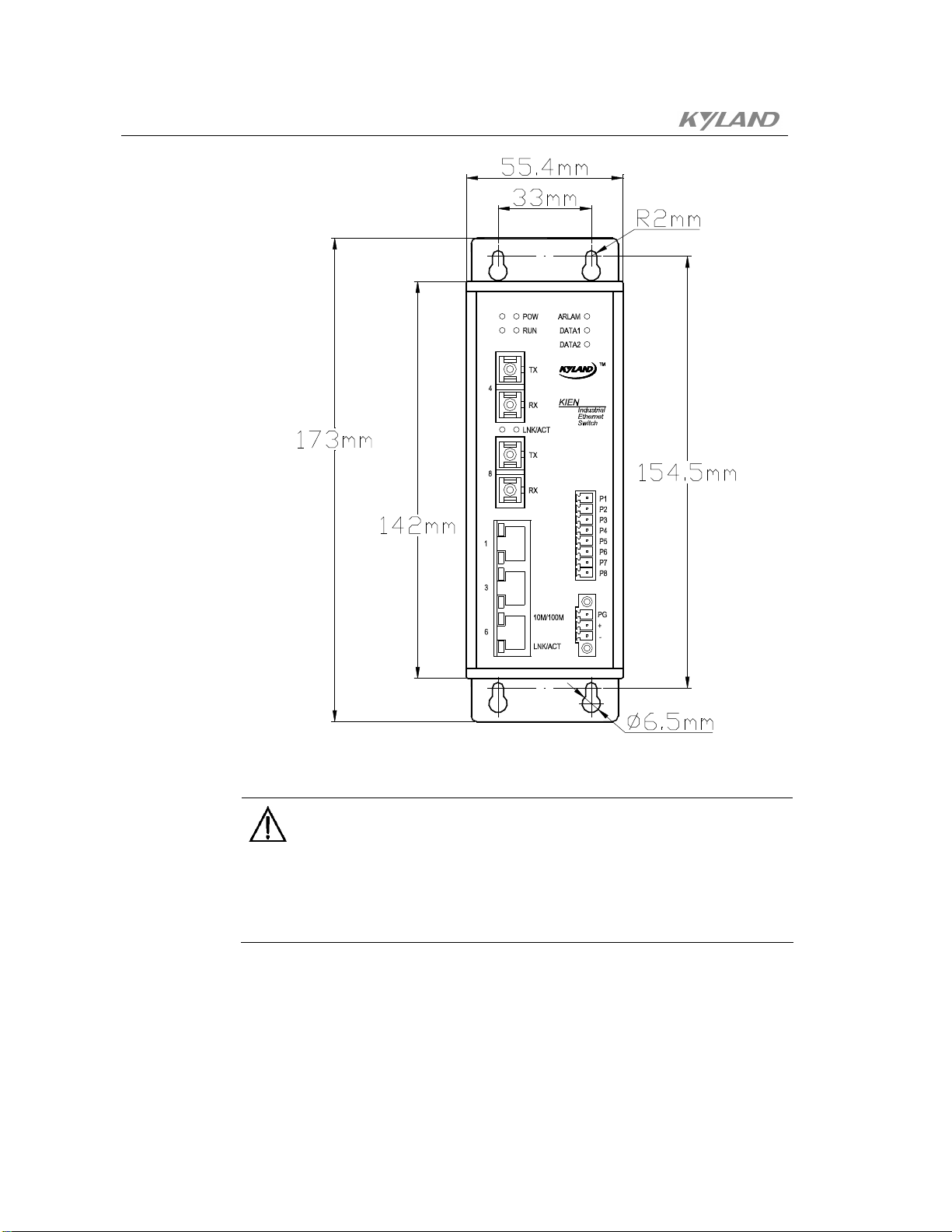
as improves the stability of the system. The profile of the case for the KIEN2032 is
shown as Figure .3-2.
Its external dimension (do not include the dimension of the DIN rail and the
wall-mounted assembly) is 142 ㎜ x 55.4 ㎜ x 120.5 ㎜ (H x W x D).
-10-

Chapter3 Hardware Architecture
The shell of this switch is a part of the whole equipment heat dissipation system. It will
get hot because of heat dissipation when the equipment works normally, do not touch
the crust when the equipment works to prevent from scalding.
3.2.2 Front Panel
The front panel of the KIEN2032 industrial Ethernet switch integrates with 2 pairs of
optical fiber interfaces, 3 10Base-T/100Base-TX Ethernet RJ45 ports, 1 power supply
input terminal, 1 data interface terminal and 9 system and port operation indication
lights as shown as Figure .3-3.
Figure .3-2 Outline drawing of KIEN2032
Warning:
-11-

KIEN2032 Industrial Ethernet Switch User's Manual
Power Supply Indicati on LED
Data Alarm LED
Syst em Running Status
Indication LED
Port 8 Indication LED
Port 4 Indication LED
Speed LED
Port Connecti on St atus
Indication LED
Figure .3-3 Front Panel Diagram
Data 1 Indication LED
Data 2 Indication LED
Data Interface Termi nal
Power Supply Input
Termi nal
-12-
Optical Fiber Interface
The KIEN2032 presents 2 pairs of 100Base-FX full duplex single mode or
multi-mode optical fiber interface with uplink redundancy; the port number is 4
and 8. The connector can select the SC or FC. The optical fiber interface should
be used in pair (TX and RX in pair), where, the TX interface is the optical
transmitting terminal which connects to the optical receiving terminal RX for the
optical interface of the remote switching, the RX is the optical receiving terminal
which connects to the optical transmitting terminal TX for the same optical
interface of the remote switch. It can take advantages of 2 pairs of 100Base-FX
optical fibers interfaces to form the optical fiber redundant ring network. The ring
network redundant recovery time is less than 300ms to improve the reliability of
the network operation effectively when the system failure occurs.
Ethernet RJ45 Port
Chapter3 Hardware Architecture
The KIEN2032 presents three 10Base-T/100Base-TX Ethernet RJ45 ports. The
port number is 1, 3 and 6, each of RJ45 ports can present the adaptive function
and support the automatic MDI/MDI-X connection. The direct connected network
cable/cross-connected network cable can be used to connect the switch with the
end equipment, server, hub and other switches. Each port supports the
IEEE802.3x adaptive function, so the optimal transmission method (half duplex
or full duplex) and data rate (10 Mbps or 100Mbps) can be selected automatically
(connected equipment must also support this features). If the equipment
connected with these ports does not support the adaptation, the port will send
correct rate, but the transmission mode is half duplex by default.
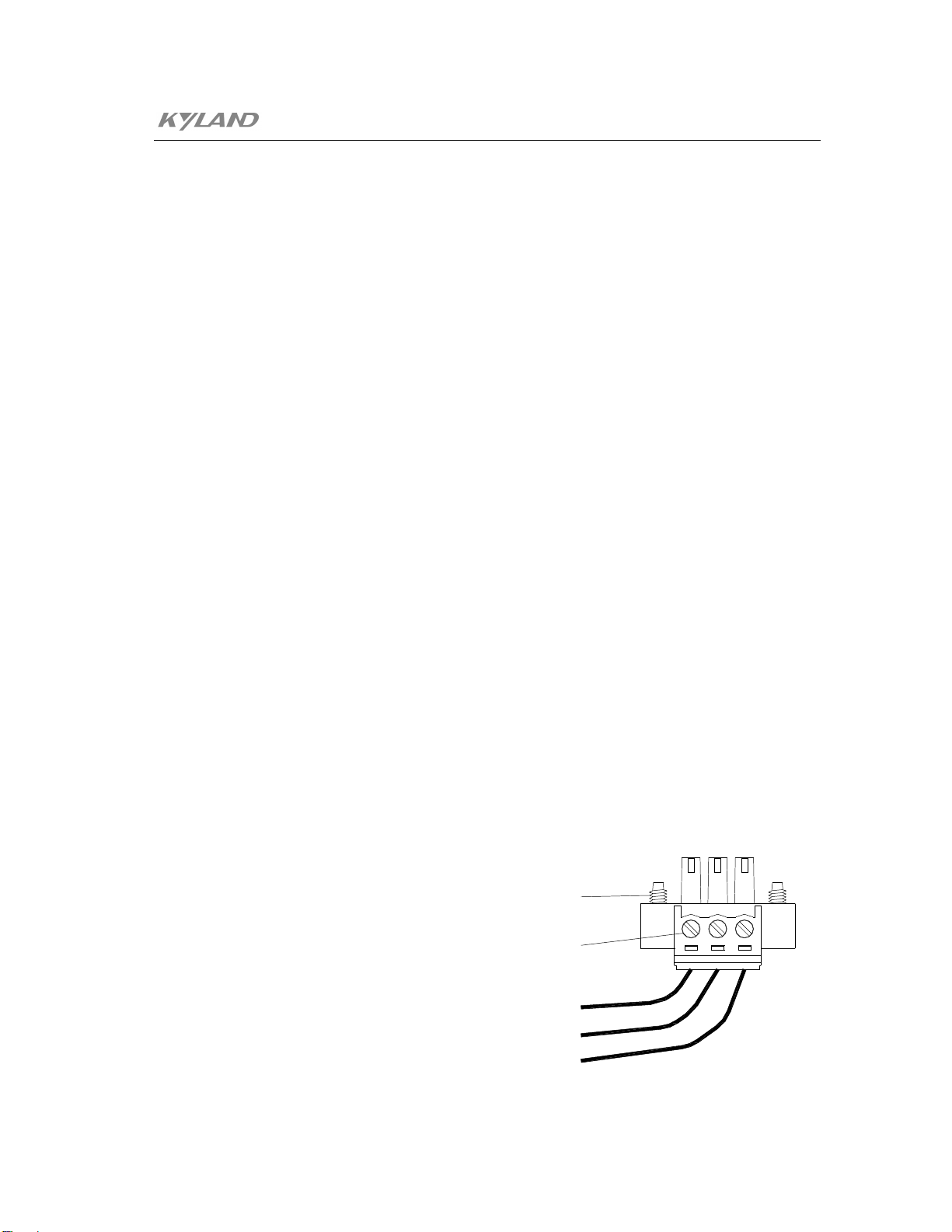
Power Input Terminal
The KIEN2032 uses the DC24V power supply. It uses the 3.81 ㎜ gap 3-wire
phoenix terminal to connect to the power supply. The diameter of the power
supply is less than 1.5 ㎜.
The sequence of the connection is shown as Figure .3-5. The connection wire and
the installation step as follows:
1. Peel off the crust of the power cable for about 5mm to twist several of
exposed copper wires into one bundle;
2. Use the 2.5mm “-“ shape screw driver to loose the “power cable lock screw,
insert the power cable into the hole at the end of the terminal, screw tightly
the “power cable lock screw”;
3. Insert the power supply terminal into the DC socket of the equipment, use
the 2.5mm “-“ shape screw driver to screw tightly two “terminal lock
screw” to fixedly connect the terminal and the power supply connector.
Termi nal Locki ng Screws
Locki ng Scr ews f or Power
Cabl es
Power Gr ound
+24V
Pr ot ect i on Gr ound
-13-

KIEN2032 Industrial Ethernet Switch User's Manual
Figure .3-4 Connection Diagram of DC Power Supply Terminal
Data Interface
The KIEN2032 presents 2 serial data, the factory default port number for the first
data is 10001, whose interface method may be RS232 or RS485 (Configured
according to the requirement of users). The factory default port number for the
second data is 10002, whose interface method is coexist for RS232 and RS485.
The connection wire terminal for the data interface is the 3.81 ㎜ gap of 8-wire
phoenix terminals, whose connection method is the same as that of the power
supply terminal. The sequence of the connection is shown as Figure .3-5.
Figure .3-5 Connection Wire Diagram of KIEN2032 Data Interface
LED Indicator
The LED indication light of the KIEN2032 front panel can display the status of
the system operation and the port, which facilitates to find problem and
troubleshooting. Table 3-1 describes the meanings of the front panel LED
indication light.
Table 3-1 Description of LED Indication Light
LED Condition Status
System Status LED
RUN
ON
Blinking
The optical fiber interface of the switch is set to the
redundant mode, the equipment is central office device.
The optical fiber interface of the sw itch is set to the
redundant mode, the equipment is set as remote.
-14-

Chapter3 Hardware Architecture
OFF
POWER
ARLAM
DATA1
DATA2
LINK/ACT
Each Ethernet RJ45 port has tw o indication lights, the yellow light is the port rate
indication light, while the green one is the port connection status indication light.
10M/100M
(Yellow
light)
LINK/ACT
(Green
light)
ON The power supply connects and operates normally.
OFF The power supply is not connected or operates abnormally.
OFF Operate normally.
Blink
ON Without Data transmission
Blink With Data transmission
ON Without Data transmission
Blink With Data transmission
Optical Interface Status LED (Optical interface 4 and 8)
ON The port has set up an effective network connection.
Blink The port has network activity.
OFF The port has not set up any effective network connection.
Light up
Extinguish
Light up The port has set up an effective network connection.
Flash The port has network activity.
Extinguish The port has not set up any effective network connection.
The optical fiber interface of the switch is set to common
direct connection mode.
Data Indication Light
Being actuating and setting incorrectly or the data circuit
fails.
Ethernet RJ45 Port Status LED
100M operating status (namely 100Base-TX)
100M operating status (namely 10Base-T)
3.2.3 Top Panel
The front panel of the KIEN2032 industrial Ethernet switch integrates with the network
management interface and the property setting switching as shown as Figure .3-6.
-15-

KIEN2032 Industrial Ethernet Switch User's Manual
Network Management Int erf ace
Network Propert y
Set t i ng Swi tch
Figure .3-6 Top Panel Structure
Network Management Interface (CONSOLE)
The network management interface of the KIEN2032 is the shielded RJ45 socket
with shield, the interface communication standard is the 3-wire RS232. Users can
use the network management wire whose one terminal is RJ45 and the other
terminal is DB9F to connect the network management interface of the KIEN2032
with the 9-pin serial port of the control computer. Run the local management
software (LocalAdmin) provided by KYLAND on the control computer, and
configure, query and manage the KIEN2032 which connects with the serial port
of the control computer directly. Connect the network management wire and the
central office equipment and run the network management software (Kyvision)
provided by KYLAND on the control computer, to implement the configuration,
query and management function for all KIEN2032 equipment in the whole
network. (For the use of the network management software and local
management software, refer to Kyvision Industrial Ethernet Switch Dedicated
Network Management User’s Manual. This network management interface and
network management software can not implement the management of the serial
data interface. For the management of the data interface, refer to the contents of
chapter 5 in this manual.
The sequence of the connection for the KIEN2032 network management interface
with the 9-pin serial port of the PC is shown as Figure .3-7.
-16-

Chapter3 Hardware Architecture
F
1
2
F
Figure .3-7 Connection Diagram of KIEN2032 Network Management Wire
Property Setting Switch
There is two bit of property setting switch for the KIEN2032, which are defined
as T and F respectively. T is used to set the redundancy mode and common direct
connection mode for 2 pair of optical interfaces. When T is switched to ON, 2
pair of optical interfaces are set to common direct connection mode. Otherwise, it
will be the redundant mode. F is used to set the office and remote property of the
equipment when the optical fiber interface is the redundant mode. If the T is
switched to OFF, the equipment is the office terminal when the T is switched to
ON. Otherwise, it will be the remote terminal. The corresponding relationship for
the concrete position and the property setting switch is shown as table3-2.
Table 3-2 Corresponding Relationship Table for Position and Property Setting Switch
Setting Switch Position
Meanings of Property
The optical fiber interface is
the redundancy mode, and
the equipment is set as
remote terminal.
The optical fiber interface is
Position Schematics
T
1 2
ON
Logical
Position
T OFF
F OFF
T OFF
T
-17-

KIEN2032 Industrial Ethernet Switch User's Manual
F
F
the redundancy mode, and
Only one terminal equipment can be set to the office terminal within the optical fiber
redundant ring network, other are remote terminal.
3.2.4 Bottom Panel
The bottom panel of the KIEN2032 presents a grounding screw hole, accompanying
with M3 * 8 grounding screw and Ф3 grounding cool pressure terminal. As is shown in
Figure .3-8, after one terminal of the grounding wire is presses to the cool press
terminal, the grounding screw is used to fix the grounding hole of the crust. Another
T
1 2
ON
Note:
F ON
T ON
T
1 2
ON
F ON/OFF
the equipment is set as office
terminal.
The optical fiber is in
common direct connection
mode.
-18-
terminal of the grounding wire is grounded reliably. The diameter of the grounding
wire is less than 2 ㎜.

Chapter3 Hardware Architecture
Figure .3-8 Grounding Method of KIEN2032 Crust
-19-


Chapter 4 Hardware Installation
4.1 Installation Requirement
The KIEN2032 industrial Ethernet switch single-body structure and can be directly
locked on the standard 35mm DIN rail or is mounted on vertical walls or internal walls
of the switch cabinet with the wall mounting part.
Before the KIEN2032 is installed, confirm whether the operation environment is
applicable firstly, including power supply demand, full space, whether it approaches
other equipment to be connected to the network equipment and whether other
equipment is in place. Please confirm following installation requirement:
1. Power Supply Requirement: The KIEN2032 standard product uses redundant DC
24V power supply (18VDC~36VDC).
2. Environment Requirement: Temperature -35 ~ 75, relative humidity
(non-condensation)
3. Grounding Resistance Requirement: <5
4. According to the configuration requirement of the contract, check whether the
cables are laid out in place and whether the connector is right.
5. Prevent direct sunshine irradiation and keep away from the heating source or the
area with strong EMC interference.
6. The KIEN2032 standard product only provides the DIN rail installation assembly,
so users only need to prepare the DIN rail. If the wall-mounted installation is
required, it is necessary to purchase the wall-mounted installation assembly.
Furthermore, users also need to prepare the screw, cap and tools for
wall-mounted installation, to ensure the reliable installation.
7. Check whether there is the cable or connector needed to install.
4.2 Installation of Main Machine
4.2.1 Rail Installation
For most of the industrial application, it is convenient to install the 35 ㎜ standard DIN
rail. When you take out of the packaging box, the rear panel of the KIEN2032 should
-21-

KIEN2032 Industrial Ethernet Switch User's Manual
have fixed green plastic DIN rail connection socket. The dimension of the rail
installation is shown as Figure .4-1. If the KIEN2032 needs to be installed to the DIN
rail, should check the installation condition of the DIN rail before it is installed. To
check the following::
1. Whether the DIN rail is fixed and firmly, whether the DIN rail is installed with
other equipments and whether there is enough space to install the KIEN2032.
2. Whether there is proper power supply connected in the rail.
Kyland Telecom
Model:
KIEN1000-8T
S/N:
E1A8T050068
CAUTION!
The casing is part of the
heat sink design , and
may be hot to the touch.
INPUT:DC18~36V @ 6VA
http:/ /www.kyland.com.cn
Made In China
DIN
Rail
Rai l
Connect i ng
Seat
Figure .4-1 Dimension Diagram of KIEN2032 Rail Installation
After the installation position of the KIEN2032 is selected, following step is complied
with to install the KIEN2032 to the DIN rail:
1. Insert the lower part of the DIN rail into the fixed rail with spring support under
the lower part of the DIN rail connection socket. Exert force slight on the bottom
panel of the KIEN2032 and turn the equipment as Figure .4-2.
-22-
2. As is shown in Figure .4-2, insert the DIN rail into the DIN rail connection socket,
confirm that the KIEN2032 equipment is installed to the DIN rail reliably.

Chapter4 Hardware Installation
Kyland Telecom
Model:
Model:
S/N:
INPUT:DC18~36V @ 6VA
Kyland Telecom
KIEN1000-8T
E1A8T050068
http://www.kyland.com.cn
Made In China
CAUTION!
The casing is part of the
heat sink design , and
may be hot to the touch.
DIN Rail
Spri ng
KIEN1000-8T
S/N:
E1A8T050068
INPUT:DC18~36V @ 6VA
http://www.kyland.com.cn
Made In China
CAUTION!
The casing is part of the
heat sink design , and
may be hot to the touch.
DIN Rail
Spri ng
4.2.2 Wall-mounted Installation
For some application occasion, it is not convenient to install the DIN rail, so it is more
applicable to use the wall-mounted installation. KYLAND can provide users with the
wall-mounted plate which is the assembly used to the wall-mounted installation for the
KIEN2032. The dimension of the wall-mounted installation is shown as Figure .4-3.
a b
Figure .4-2 Install KIEN2032 to DIN Rail
-23-
KIEN2032 Industrial Ethernet Switch User's Manual
-24-
Figure .4-3 Dimension Diagram of KIEN2032 Wall-mounted Installation
Note:
The wall-mounted plate is not the standard configuration of the KIEN2032. If it is
necessary for our company to provide this configure, please order it individually when
you purchase.
The installation steps of the KIEN2032 wall-mounted installation as follows:
1. Use the “+” screw driver to loose the two screws which is used to fix the DIN rail
connection socket on the KIEN2032 equipment firstly, disassemble the green
Chapter4 Hardware Installation
DIN rail connection socket.
2. Take out the wall-mounted plate and the wall-mounted plate screw from the
packaging (“+” rail screw M3 * 6). Use the “+” screw driver to install the
wall-mounted plate to the position where the DIN rail connection socket was
installed. The installation direction of the wall-mounted plate is shown as
Figure .4-4.
Wal l - mount i ng
Pl at e
Figure .4-4 Installation of Wall-mounted Plate
3. Selection of Installation Position: Vertical wall or inner wall of the case. If it is
selected to install to the wall vertically, it is suggested to use the Ф6 plastic
expansibility blot and Ф3 self-contained screw to install the equipment.
According to the installation dimension of the annotation in Figure .4-3, the
impulse electric drill is used to punch 4 Ф6 holes in wall, whose depth should be
able to contain the Ф6 plastic expansibility blot. After the plastic expansibility
blot is plugged into the hole, use the “+” screw driver to screw the self-contained
screw into the plastic expansibility blot, but don’t screw it tightly and remain
-25-

KIEN2032 Industrial Ethernet Switch User's Manual
about 5mm distance. If it needs to install to the inner wall of the case, it is
suggested to drill 4 M2 screw holes in the inner wall of case according to the
installation dimension when the case is made, or use the electric drill to punch 4
Ф4 holes on scene by hand. Use the “+” screw driver to install the “+” rail screw
of 4 M3 * 10 to the 4 holes. If there is no screw in the hole, it is necessary to
install 4 M3 screw at the back. Finally, the screw should not be screwed tightly
and retain about 5mm distance.
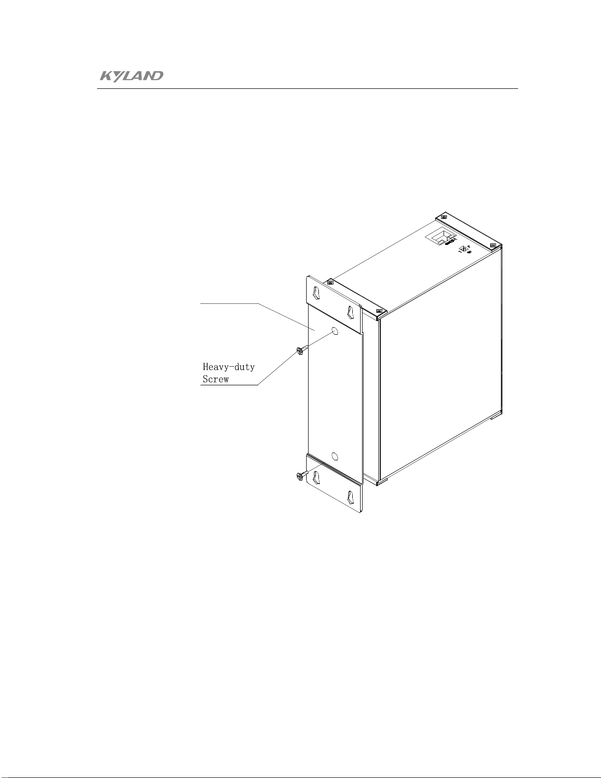
4. After fixing the screw to the wall, install the KIEN2032 to selected position to
enable 4 screws to pass through 4 Ф6.5 holes of the wall-mounted plate. Slip
down the KIEN2032. It is shown as Figure .4-5. Screw tightly 4 screws. The
KIEN2032 is fixedly installed to the wall or the inner wall of case.
-26-
Figure .4-5 Schematics of Wall-mounted Installation Process

Chapter4 Hardware Installation
4.3 Cable Connection
After the KIEN2032 is installed correctly, the installation connection of cable can be
implemented. The cable connection of following interface is mainly contained.
1. Service Interface
The terminal equipment interface provided by KIEN2032 is
10Base-T/100Base-TX Ethernet RJ45 interface, which is connected
straight-through to the end devices and cross-over to the networking devices.
2. Connect Network Management Interface
The KIEN2032 connects with the serial port of the control computer by the
CONSOLE interface of top panel, so users can make a network management
wire with suitable length according to Figure .3-7.
3. Connect Serial Port
Select the RS232 or RS485 interface according to the type of the serial port and
it can connect up to 2 channels of data.
4. Connect Power Supply
The KIEN2032 equipment uses the DC 24V power supply according to the
indication of the product label. After connecting all other cable, the power
supply can be connected.
4.4 Optical Fiber Connection
The KIEN2032 provides 2 pairs of redundant 100Base-FX full duplex single mode or
multi-mode optical fiber interface. These optical fiber interfaces can be used to
establish the optical fiber redundant ring network. When the failure for some
equipment of the optical cable within the network occurs, the network will recover
within 300ms. The SC or FC can be selected as the connector of the optical fiber
interface according to the requirement.
-27-
KIEN2032 Industrial Ethernet Switch User's Manual
Warning:
This switch uses the laser to transmit the signal on the fiber cable. The laser complies
with the level 1 requirement of the laser product, the general operation does not harm
to your eyes. However, when it powers on, do not watch the optical transmission port
and the end face of the optical fiber terminator by naked eye.
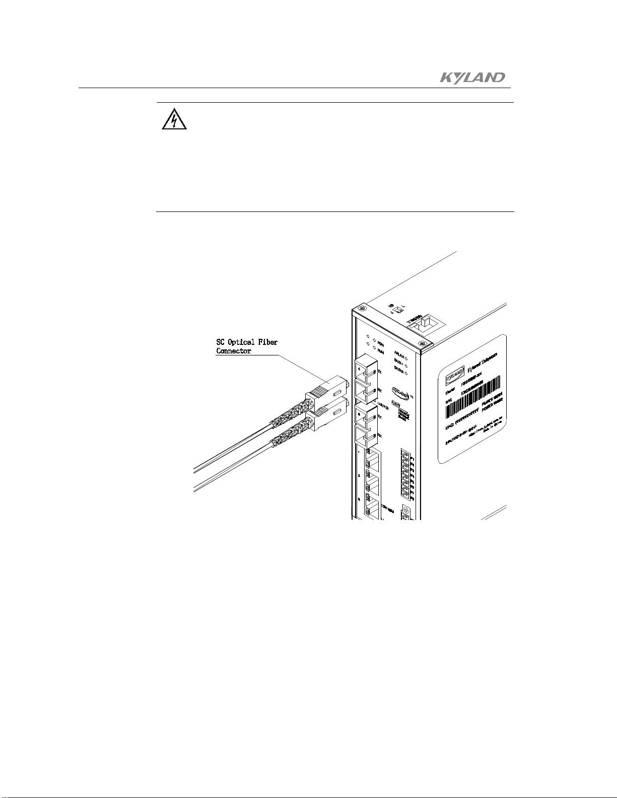
The step for connecting the inserted optical fiber module as follows:
-28-
Figure .4-6 Connection of Optical Fiber Port
1. Remove and keep the rubber cover of the SC or FC port. When it is not used, use
the rubber cover to protect the optical fiber terminator.
2. Check whether the optical fiber terminator is clean. Dip into the clean paper
towel or tampon, wipe off the cable connector gently. The dirt optical fiber
terminator will reduce the quality of the optical transmission, which will have an
effect on the performance of the port.

Chapter4 Hardware Installation
3. Connect one terminal of the optical cable to the optical fiber interface of the
4. After the connection completes, check the optical interface LNK/ACT indication
4.5 Cable Layout
The layout of the cable should comply with following conditions:
1. Check whether the specification, model and quantity of all cables complies with
2. Check whether the cable is damaged and there are some certificate of factory
switches, another terminal is connected to the optical fiber interface of another
equipment. It is shown as Figure .4-6.
light which corresponds to the front panel of the switch. If the indication lights
up, it indicates that the connection is effective.
the design of the engineering drawings and the requirement of contract before
the cable is laid out.
record and quality assurance before the cable is laid out.
3. The specification, quantity, direction of routing and placement of all cables to be
laid out should comply with the requirement of drawing design, the layout length
of each cable should be determined according to the actual position.
4. There should not be broken wire or tie-in among layout cables.
5. The user cable should be separated to work out from the power cable.
6. The cable should be straightly arranged with smoothly, round and even bend in
the walkway.
7. The cable should be straight arranged in the groove and should not be out of the
groove to keep the way of other incoming and outgoing cable hole. It should be
bounded and fixed in the outgoing groove part or the cable bend.
8. When cables, power cables and grounding wires are in a casing, they shall not
overlap. If they are too long, they shall be tidily coiled and placed in the middle
of chutes and they shall not be placed on other cables and wires.
-29-

KIEN2032 Industrial Ethernet Switch User's Manual
9. When the tail cable is laid out, the optical cable knot should be prevented and
turning should be reduced as much as possible. Furthermore, the turning radius
should not be too small. The knot should be tightened moderately and should not
be too tightened. When they placed on chutes, they shall be separated from
others.
10. There should be corresponding identification at both ends, and the contents of
the identification should be simple and easy to maintain.
Note:
When the tail cable is laid out, the optical cable knot should be prevented and turning
should be reduced as much as possible. Furthermore, the turning radius should not be
too small. Otherwise, it will cause the serious loss of the link optical signal. Have an
effect on the quality of the communication.
-30-

Chapter 5 Configuration and Application of
Data Port
5.1 Configuration of Data Port
In KIEN2032, a serial data server is built in, which transfers the two serial data into
TCP/IP protocol and connects to the Ethernet. The TCP/IP protocol can support both
the connection-based TCP protocol and the connectionless UDP protocol. Hence, any
computer on the network can control the serial port equipment and share the
information of the serial port equipment.
Users can log on the console network management of the serial data server via super
terminal by the serial port 1 of the KIEN2032 or in the Ethernet interface Telnet way,
even log on the WEB network management of the serial data server in the Ethernet
interface WEB way. Above three network management methods can set the IP address
and the operation method of the KIEN2032 serial data server. Before using the
equipment, the data interface of the KIEN2032 should obtain unique IP address to
implement remote setting and the normal operation. The IP address of the KIEN2032 is
set to 192.168.0.123 and the subnet mask is 255.0.0.0 as a factory default.
5.1.1 Logon Console Network Management
1. Logon Serial Port Console Network Management
-31-

KIEN2032 Industrial Ethernet Switch User's Manual
Figure .5-1 Logon Serial Port Console
Use serial port wire to connect the serial port of one control computer to the
serial port1 of the KIEN2032, open the super terminal program of the output
which is set to 9600, 8, none, 1 and without traffic control. Continuously enter
3 lowercase x characters to the super terminal window when it is powered on
the KIEN2032, until the super terminal window displays the setting menu. It is
shown as Figure .5-1.
2. Logon Telnet Console Network Management
Use cross-over cable or straight-through cable to connect any Ethernet RJ4 port
of the KIEN2032 to the network or the user computer network interface card
firstly. Please type telnet 192.168.0.123 9999 into the Run window of Windows
or the MS-SOS command line prompt. The TELNET window will display the
setting menu. The contents of menu should be completely consistent with the
logon serial port console network management. It is shown as Figure .5-2.
-32-

Chapter5 Configuration And Application of Data Port
5.1.2 Console Network Management
The console network management can provide 8 menu items: 0 Server setting; 1 Serial
port 1 setting; 2 Serial port 2 setting; 5 Advance setting; 6 Security setting; 7 Factory
setting; 8 Exit without saving; 9 Save and exit. Following will introduce the console
network management menu item by item.
1. Server Setting
It will set the parameter of the KIEN2032 serial data server when 0 is selected,
such as IP address, subnet mask and gateway. Note that the IP address should be
unique in the LAN. The subnet mask setting is defined by adopting the bits of the
actual binary mask 0, such as the 255.255.255.0 is set to 8. If it is set to 0, it will
adopt corresponding subnet mask according to the type of the IP address, the
subnet mask corresponding relationship is shown as follows.
Figure .5-2 Logon Telnet Console
-33-

KIEN2032 Industrial Ethernet Switch User's Manual
Table5-1 Corresponding Table of Subnet Mask
Subnet Mask KIEN2032 Serial Data Server
Setting
255.255.255.252 2
255.255.255.248 3
255.255.255.240 4
255.255.255.224 5
255.255.255.192 6
255.255.255.128 7
255.255.255.0 8
255.255.254.0 9
255.255.252.0 10
255.255.248.0 11
..
..
255.128.0.0 23
255.0.0.0 24
This item should also contain the Telnet password setting and provide the telnet
port 9999 with password protection. This password is up to 4 bit. When there is
password, it will give the password input prompt before using the Telnet firstly.
2. Serial Port Setting
When 1 or 2 is selected, it will set the parameters of serial part1 or serial part2 for
the KIEN2032.
Baud rate: the effective baud rate is 300,600, 1200, 2400, 4800, 9600 (by
default), 19200, 38400, 57600 or 115200. The equipment will remind promptly
when the input error occurs.
Interface Mode: It is the two bytes of hexadecimal which is used to define the
type of interface , word length, check bit and stop bit of the for the serial port.
The corresponding binary is defined as shown in following table:
-34-

Chapter5 Configuration And Application of Data Port
Table5-2 Binary Corresponding Table of Interface Mode
Option Bit7 6 5 4 3 2 1 0
RS-232C 0 0
RS-422/485 0 1
RS-485
1 1
2-wire
7 bit of
1 0
word length
8 bit of
1 1
word length
Without
0 0
check
Odd check 0 1
Even check 1 1
1 stop bit 0 1
2 stop bit 1 1
Where, the type of common value is shown as follows:
Table5-3 Corresponding Table of Common Interface Mode
Type Binary Hexadecimal
RS232C, 8 bit, without check, 1 bit of stop bit
01001100 4C
(by default)
RS232C, 7 bit, event check, 1 bit of stop bit
01111000 78
RS485 2-wire, 8 bit, without check, 1 bit of
01001111 4F
stop bit
RS232C, 8 bit, odd check, 2 bit of stop bit
11011101 DD
Flow Control: it is the two hexadecimal which is used to set necessary
communication handshake method. In general, if the data block is less than 1K or
the rate is less than 9600, it is not necessary to adopt the flow control. The
concrete value is defined as following table.
-35-

KIEN2032 Industrial Ethernet Switch User's Manual
Table 5-4 Value Corresponding Table of Traffic Control
Type Hexadecimal
No Flow Control (by default) 00
XON/XOFF Software Control 01
RTS/CTS Hardware Control 02
XON/XOFF Control, but the control character is
05
also transmitted to the host.
Port Number: The local port number of this serial port. For the TCP protocol, it
is the port number intercepted locally. For the UPD protocol, it is the local port
number which is binding. Typically value scope is 1024 - 65535.
Note:
14000~14009 Reserve for some serial port to redirection the software.
9999 Reserve for the use when TELNET logon.
30718 Reserve for parameters setting.
Connection Method: it is the two hexadecimal which is used to set the operation
method of the network connection, define the operation method of TCP Server,
TCP Client or UDP protocol. The corresponding binary definition is shown as
following table:
-36-
Table5-5 Binary Value Corresponding Table of Connection Method
Category Type 7 6 5 4 3 2 1 0
Don’t accept
0 0 0 0
connection.
Controlled by
0 1 0 0
TCP Server
DCD.
Accept the
connection
1 1 0 0
unconditionally.
Don’t accept
TCP Client
0 0 0 0
actively.

Chapter5 Configuration And Application of Data Port
Any character
0 0 0 1
connection.
Controlled by
0 0 1 0
DCD.
Manual
0 1 0 0
connection.
Power on
automatic
0 1 0 1
connection.
UDP
UDP 1 1 0 0
Protocol
Redisplay 1 0 1 1 0 Modem
Simulation
Don’t redisplay 0 0 1 1 0
Mode
Manual connection: When the connection method is set to manual connection, the
KIEN2032 can accept the command sent from the serial port and execute the
connection request to the remote host. The command consists of uppercase C +
Remote IP address +/ port number.
For instance: Suppose that the IP address of one terminal of the KIEN2032 is
192.168.0.123 with port number 10001, then C192.168.0.1/10002 will attempt to
set up the connection whose IP address is 192.168.0.1 and port number is 10002.
Automatic Connection: It will launch the connection automatically after the
KIEN2032 powers on according to predefined remote IP address and port
number.
Type of Data Packet: When the datagram type is prompted, 01 is entered to
represent the UDP protocol.
Modem Simulation Mode: When the connection method of the KIEN2032 is set
to the modem simulation mode, the KIEN2032 is equivalent to a modem for the
equipment which connects to other serial ports, KIEN2032 can receive the AT
command request from the serial port. Hence, it can use Ethernet to replace
previous dial connection and need not to modify any dial-based management
software. When the KIEN2032 is set to the modem simulation mode and the
serial port is in the idle status, the KIEN2032 can still be taken as the server to
-37-

KIEN2032 Industrial Ethernet Switch User's Manual
receive the connection request from the remote client.
Redisplay: it means the redisplay of the AT command and response.
Remote IP Address: This predefined IP address will be used when the automatic
connection method is used.
Remote Port Number: Attempt to set up the remote port number for the
connection. When the KIEN2032 is used as the telnet UNIX system host for the
terminal, the port number should be set to 23.
Disconnection Mode:It is the two hexadecimal which is used to set the
disconnection mode of the serial port connection. The definition of corresponding
binary is shown as following table:
Table5-6 Binary Value Corresponding Table of Disconnection Method
Type 7 6 5 4 3 2 1 0
Terminated by DCD 1
DCD neglected 0
Telnet method 1
Serial port password protection 1
Forced termination 0
Forced termination is prohibited 1
Close the LED indication light
1
when there is the connection .
Closed by EOT (^D)
1
DCD is outputted by the DCE equipment.
KIEN2032 will send the type of the terminal when it requests the
connection.
The password requires to be provided when remote host request the
connection.
Whether the confirmation signal for termination of opposite side, the TCP
connection will be terminated compulsively.
If the TCP is set up, LED indication light will be closed but not flashed.
-38-
When x40h is monitored from the data of the serial port, the connection

Chapter5 Configuration And Application of Data Port
will be closed. (Only when both the Telnet method and the EOT method
are set at the same time, this function acts.)
Clear Buffer Mode: It is the two hexadecimal which is used to set the clear
method of the buffering area data for the serial port and network interface when
the connection is set up or terminated. The corresponding binary is defined as
shown in following table:
Table5-7 Binary Value Corresponding Table of Clear Buffer Mode
Type 7 6 5 4 3 2 1 0
Receiving Buffer Area (From serial port to network interface)
Clear when the serial port
1
launches the connection.
Clear when the network interface
1
launches the connection.
Clear when the connection
1
terminated.
Receiving Buffer Area (From network interface to serial port )
Clear when the network interface
1
launches the connection.
Clear when the serial port
1
launches the connection.
Clear when the connection
1
terminated.
Packet Algorithm
Packet Algorithm is allowed. 1
Data Packet Control: It is the two bytes of hexadecimal which is used to control
the data packet when the clear buffer method setting is allowed to the packet
algorithm. The definition of corresponding binary is shown as following table:
-39-

KIEN2032 Industrial Ethernet Switch User's Manual
Table5-8 Binary Value Corresponding Table of Data Packet Control
Type Type 7 6 5 4 3 2 1 0
Wait 12ms to send 0 0
Waiting the
serial port
Wait 52ms to send 0 1
Wait 250ms to
1 0
idle time
send
Wait 5ms to send 1 1
None 0 0
Send
1 0 1
character
2 1 0
Double byte 1 Followed
character
Single byte 1
Disconnect time: The format is mm:ss. When the setting is 00:00, it indicates
that the idle time is inifitely large.
Sending Character: Two characters can be set to immediate sending characters.
When any one is received, this character together with the data the serial port
buffered will be packaged to send. In this way, it can reduce the response time of
some protocol packet or partition the whole serial port protocol into several
network data packet. When one character is set to 00, the sending character
function will be shielded. 2 sending characters can also be taken as the two bytes
sequence. Namely, it will immediately send only when the two bytes is received,
-40-
this function will be valid when the sending character is two bytes in the data
packet control.
Following Character: The character followed the sent characters, such as single
check or CRC check. If the following character is set, it will wait for one or two
following characters after receiving the character and then send the data packet
the serial port buffered to the network.
Terminal Name: If the telnet connection method is set in the termination
connection mode, the type of terminal is set in here, namely the name of terminal.
Port Password: If the port password protection is set in the termination
connection mode, the password is entered from here and the longest one is 16 bit.
Chapter5 Configuration And Application of Data Port
3. Factory Setting
All parameters will be restored to the factory default value if 7 is selected.
However, the IP address, subnet mask and the gateway will be kept constantly.
4. Exit without saving
Previous modification will be invalid and the KIEN2032 will restart.
5. Save and Exit
Save previous parameters modification, exit and restart the KIEN2032.
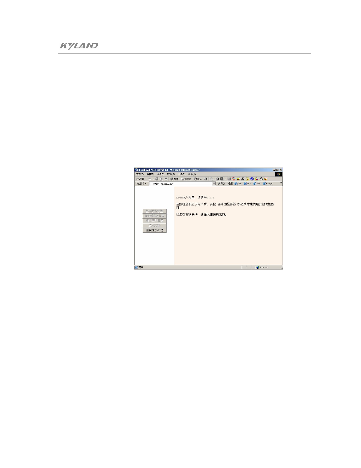
5.1.3 WEB Network Management
Figure .5-7 Logon WEB Network Management
If the WEB method is expected to use, modify the IP address of the computer which is
used to set to be within the same network segment with the KIEN2032.
Use ping command in the computer after the KIEN2032 is connected to the network
correctly such as ping 192.168.0.123
After the response is confirmed correctly, launch the IE browser and enter
192.168.0.123 into the address column, the interface as is shown in Figure .5-7 is
obtained. Click “Connect DN Server” button to enter the main menu of the KIEN2032
serial data server WEB network management as shown in Figure .5-8.
-41-

KIEN2032 Industrial Ethernet Switch User's Manual
Figure .5-8 WEB Network Management Main Menu
1. Basic Parameter Setting
-42-
Figure .5-9 Basic Parameter Query
This page indicates the basic information of KIEN2032 such as IP address,
subnet mask, gateway address, MAC address and the parameters of two serial
ports. The parameters can not be set at this page.
2. Server Parameters Setting
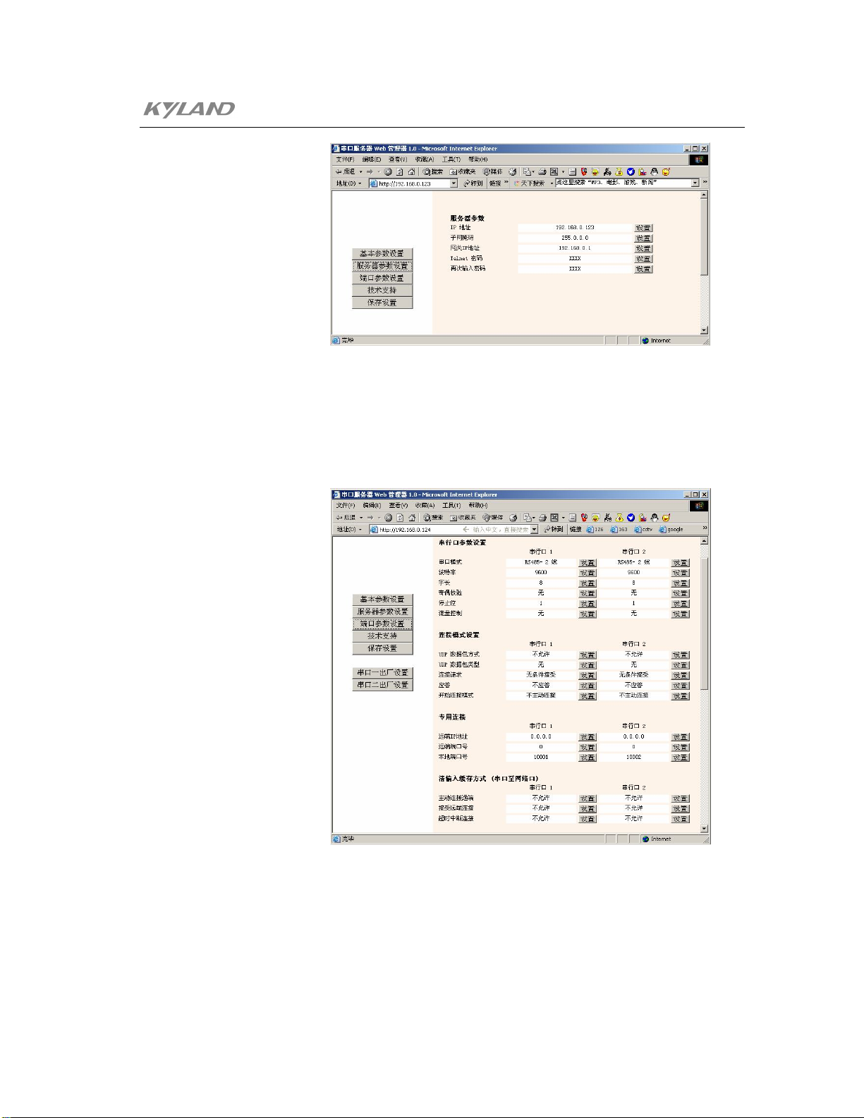
Chapter5 Configuration And Application of Data Port
Figure .5-10 Basic Parameter Setting
This page sets the IP address, subnet mask, gateway IP address and TELNET
logon password of KIEN2032.
3. Ports Parameters Setting
Figure .5-11 Serial Ports Parameter Setting
This page can set various parameters of serial port 1 and serial port 2. For the
meanings of various items, refer to the introduction of the console network
management.
-43-

KIEN2032 Industrial Ethernet Switch User's Manual
This page can also restore the individual setting of serial port 1 and serial port 2
to the factory default setting.
5.2 Application of Data Ports
5.2.1 As TCP Server
The KIEN2032 takes the TCP server method to implement the transfer and
transmission from the serial port data to the network ports. After the KIEN2032 in
network is configured with unique IP address and corresponding port number, the
KIEN2032 starts to intercept. If there is some host which launches the connection in
network, the data ports of KIEN2032 will accept the connection request and send the
data received from the network port to the serial port, and then send the data received
from the serial port to the network port by the TCP/IP protocol packet. The KIEN2032
will not resolve and change any user’s data packet and provide fully transparent data
channel. The setting is shown as follows:
Port number: (10001)
Connection Method: (C0)
Remote IP Address: (000). (000). (000). (000)
Remote Port Number: (00000)
The implement method for the communication between two network hosts and
KIEN2032 serial port:
1. Use Winsock Programming
The user who is familiar with the network programming can use the Winsock
programming and launches the connection to KIEN2032. After the connection
is set up successfully, it can read/write the data transparently.
2. Use Virtual Serial Port (Serial Port Redirection) Software
It can implement virtual serial ports up to 255 in the computer by installing the
Serial IP virtual serial port software of our company, the data that accesses
these virtual serial ports will be sent to KIEN2032 from the network. The data
the KIEN2032 serial port received will also be transmitted to the virtual serial
port from the network. There is no difference between the operation for user to
the virtual serial port and the actual serial port operation. User can not modify
-44-

Chapter5 Configuration And Application of Data Port
5.2.2 As TCP Client
In the optical fiber network of KIEN2032, if one terminal is set to the TCP server way,
another terminal is set to the TCP Client way. The TCP Client powers on to connect the
server automatically, and implement the point to point connection between two serial
data ports. If the IP address of server is 192.168.0.100 and the port number is 10002.
The setting is shown as follows:
Port number: (10001)
Connection Method: (C5)
Remote IP Address: (000). (000). (000). (000)
any serial port-based application software and use the serial port equipment
from the network directly.
The port number must be one from 14001 to 14009 when the serial port
redirection is used. The IP address of the serial port redirection software is set
to that of KIEN2032, the port number is set to 3001 (14001-11000 = 3001), the
porting setting item can not select Raw Mode.
5.2.3 UDP Method
In UDP mode, the serial port receives the network data and retransmits it to the preset
port number with predefined IP address constantly, but not sets up the connection in
advance. If the preset IP address is set to the broadcast address of the network segment,
it will implement the point to point communication of the serial port.
Following setting can implement the point to multi-point communication from point A
to point B or C.
Remote Port Number: (00000)
-45-

KIEN2032 Industrial Ethernet Switch User's Manual
Equipment A Equipment B Equipment C
IP Address: 192.168.0.123
Subnet Mask: 8
Gateway: None
Serial Port 1:
Baud Rate: 9600
Interface Mode: 4C
Flow Control: 00
Port number: 10001
Connection Method: CC
Type of Data Packet: 01
Remote IP Address:
192.168.0.255
Remote Port Number:
10002
IP Address: 192.168.0.124
Subnet Mask: 8
Gateway: None
Serial Port 1:
Baud Rate: 9600
Interface Mode: 4C
Flow Control: 00
Port number: 10002
Connection Method: CC
Type of Data Packet: 01
Remote IP Address:
192.168.0.123
Remote Port Number:
10001
IP Address: 192.168.0.125
Subnet Mask: 8
Gateway: None
Serial Port 1:
Baud Rate: 9600
Interface Mode: 4C
Flow Control: 00
Port number: 10002
Connection Method: CC
Type of Data Packet: 01
Remote IP Address:
192.168.0.123
Remote Port Number:
10001
-46-

Chapter 6 Testing Methods
6.1 Self Testing
When the power is connected, all service indicators on the front panel will flash one
time, which means normal running of these ports. 。At the same time, the ARLAM
indication light will be off after blinking for several times, which indicates that the self
testing of the data server is normal. After that, corresponding POW will light up
constantly, the DATA1 and DATA2 will light up for a long time. RUN light is set to
on/flash/off according to the setting of the properties switch.
6.2 Testing of Ethernet Ports
As showed in the Figure 6-1, the KIEN2032 is powered on to connect any two Ethernet
ports with two testing computers with direct link network wires. Send PING command
each other. If the hardware of the tested Ethernet ports runs normally, any one
computer is able to ping the other correctly without package loss. Also, yellow
indicators of corresponding port are on when network cards of computers are in 100M
status or off when in 10M status, and green indicators of corresponding ports are
blinking. It indicates that the hardware of tested two Ethernet Ports work normally. The
same method is used to test all other Ethernet ports (For detailed operation of the PING
command, refer to the following examples.).
t est i ng comput er1
Figure 6-1 Testing of Electric Ports
t est i ng computer2
-47-

KIEN2032 Industrial Ethernet Switch User's Manual
6.3 Testing of Fiber Ports
Use two KIEN2032 switches to build an optical fiber link network as is shown in the
Figure .6-2. Connect any one fiber port of a switch with a testing computer with direct
link network wires. Send the PING command each other. If the hardware of the tested
fiber ports runs normally, any one computer is able to PING the other without package
loss. At the same time, the LINK/ACT indicator of corresponding fiber port is on. It
indicates that the hardware of tested two fiber ports work normally. The same method
is used to test another pair of fiber ports (For detailed operation of the PING command,
refer to the following examples.).
KIEN2032
t est i ng comput er 1
KIEN2032
t esti ng comput er 2
Figure 6-2 Testing of Optical Ports
An Example of the PING Command:
The IP address of the testing computer 1 is 192.168.100.10 and the 2 is
192.168.100.11.On the testing computer 1, run “cmd” in the WIN2000 operating
system or “command” in the WIN98/95 operating system from “Run” in the “Start”
menu. Send “ping 192.168.100.11 –l 1000 –t”. (-1 means byte number of the sent data
package; -t means continuously sending data). On the testing computer 2, run “cmd” in
the WIN2000 operating system or “command” in the WIN98/95 operating system from
“Run” in the “Start” menu. Send “ping 192.168.100.10 –l 1000 –t”. If switches run
normally, the testing computer 1 returns “Reply from 192.168.100.11:bytes=1000
time<10ms TTL=128” and the 2 returns “Reply from 192.168.100.10:bytes=1000
time<10ms TTL=128”, and the counted package loss rate is zero checked by the
CTL+C command ten minutes after running.
-48-

Chapter6 Testing Methods
6.4 Data Ports Test
The KIEN2032 presents two channels of data and the interface of one may be RS232
or RS485. However, only one interface outputs at one time. The interface of the second
one presents both RS232 and RS485 output. However, the RS232 and RS485 of the
same channel can not be used at the same time. The RS232 interface for the first
channel of data for KIEN2032 is connected to the COM1 port of the test computer2 or
the RS485 interface of the first channel of data is connected to the COM2 port of the
test computer2 by the RS232/RS485 convertor. The RS232 interface for the second
channel of data for KIEN2032 is connected to the COM2 port of the test computer2 or
the RS485 interface of the second channel of data is connected to the COM2 port of the
test computer2 by the RS232/RS485 convertor. Any electric ports of the equipment are
connected to the network ports of the test computer1 by the direct link network wire as
shown in Figure .4-3.
DATA1 RS485
DATA1 RS232
DATA2 RS485
testi ng computer 1
Figure 6-3 Testing of Data Ports
RS485/RS232
DATA2 RS232
COM1
RS485/RS232
COM2
testi ng computer 2
Test Data 1:
Run the super terminal on the test computer 1, select TCP/IP (Winsock) as “use when
connection", 192.168.0.123 is entered into the “Host Address”, 10001 is entered into
“Port Number”. Click “OK”. Click the call button in toolbar after the super
terminal window is opened. Run the super terminal on the test computer2, the “Use
when connection" selects the COM1. The window at the port setting is set to 9600, 8,
none, 1 and none. Click “OK”. Click the call button in toolbar after the super
terminal window is opened. At this time, any character entered from the super terminal
window of the test computer 1 should be displayed in the super terminal window of the
-49-

KIEN2032 Industrial Ethernet Switch User's Manual
test computer 2. In this way, any character entered from the super terminal window of
the test computer 2 should be displayed in the super terminal window of the test
computer 1. The test of data 1 is normal.
Test Data 2:
Run the super terminal on the test computer 1, select TCP/IP (Winsock) as “use when
connection", 192.168.0.123 is entered into the “Host Address”, 10002 is entered into
“Port Number”. Click “OK”. Click the call button in toolbar after the super
terminal window is opened. Run the super terminal on the test computer 2, the “Use
when connection" selects the COM2. The window at the port setting is set to 9600, 8,
none, 1 and none. Click “OK”. Click the call button in toolbar after the super
terminal window is opened. At this time, any character entered from the super terminal
window of the test computer 1 should be displayed in the super terminal window of the
test computer 2. In this way, any character entered from the super terminal window of
the test computer 2 should be displayed in the super terminal window of the test
computer 1. The test of data 2 is normal.
-50-

Chapter 7 Networking Modes and System
Configuration
7.1 Networking Modes
Each of KIEN2032 industrial Ethernet switches provides three 10Base-T/100Base-TX
Ethernet RJ45 ports. Each port can be directly connected with a end device or another
industrial Ethernet switch/hub before the terminal for share link. The KIEN2032
industrial Ethernet switch also presents two pair of 100Base-FX single mode or
multi-mode optical fiber interface with uplink redundancy. It can take advantage of the
uplink redundant optical fiber interface to form the optical fiber redundant ring
network, the recovery time for the ring network redundancy is less than 300ms when
the system failure occurs. It can be broadly applied to power plant, transportation,
energy, water processing and large-sized plant automatic control field and office
dispatching field.
The most typical networking mode of KIEN2032 is the redundant ring network. The
KIEN2032 builds the optical fiber redundant ring network, as showed in the Figure ure
7-1. One switch is set as the central office device and others are set as remote. In case
of breaking of the optical fibers, communication can be recovered within 300ms.
Note:
In networking of the redundant ring network of KIEN2032, we recommend to
connect the port 4 with the port 8. In other words, the port 4 of a unit connects with
the port 8 of another unit. It is shown as following diagram.
-51-
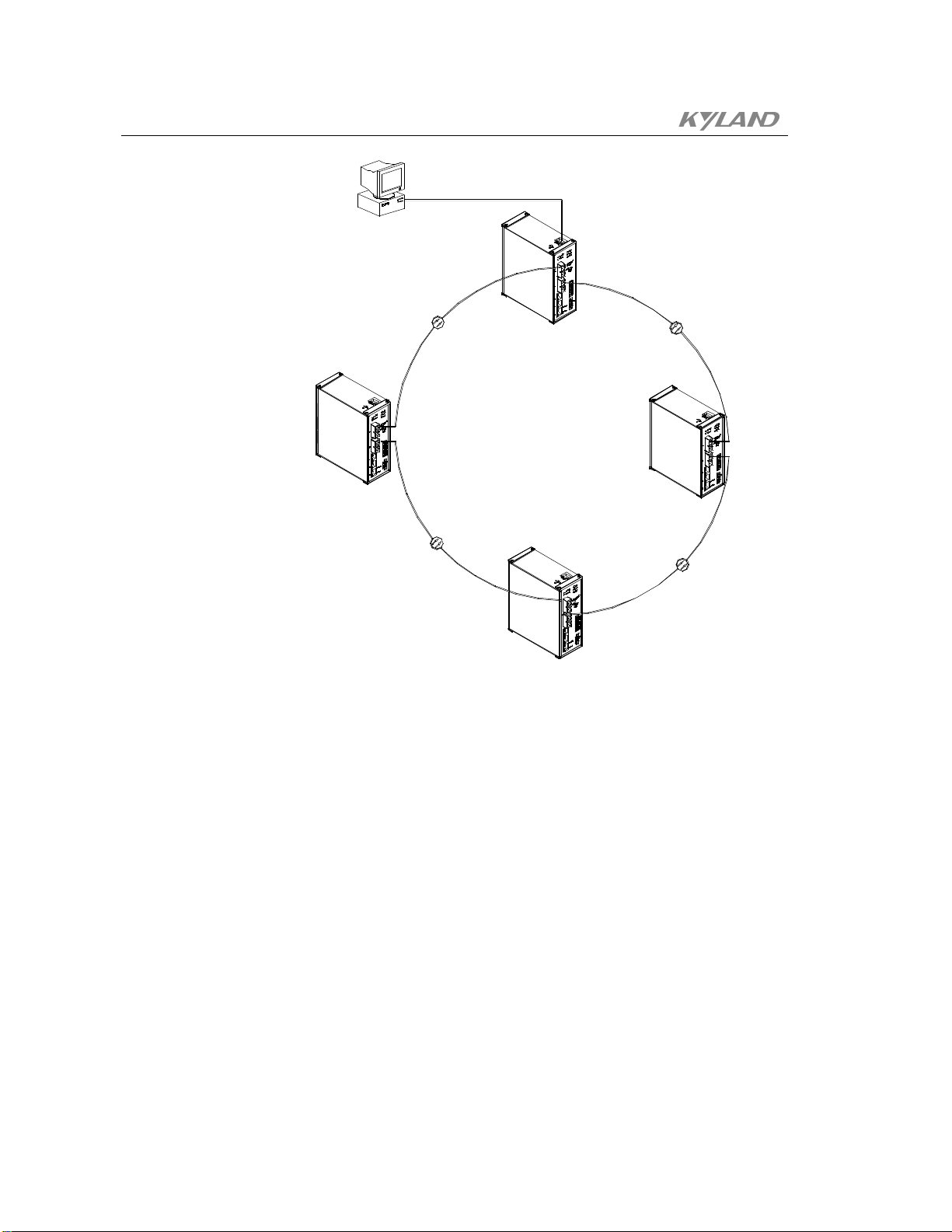
KIEN2032 Industrial Ethernet Switch User's Manual
COMPUTER
ROT
Figure 7-1 Optical Fiber Redundant Ring network of KIEN2032
COT
ROT
ROT
7.2 System Configuration
The KIEN2032 industrial Ethernet switches adopt integrated structure with the
standard configuration of 3 10Base-T/100Base-TX Ethernet RJ-45 ports and 2
redundant 100Base-FX optical fiber ports are configured fixedly. The optical fiber
interface can be customized to single mode/multi-mode. The specification of the power
supply is fixed DC24V. The data interface can provide 3 data interfaces. Where, the fist
one can be outputted to the RS232 or RS485 interface, the second data can be
outputted to fixed RS232 interface and RS 485 interface. Their specific configuration
and models are showed in the Table 7-1.
-52-

Chapter7 Networking Modes And System Configuration
Table 7-1 Configuration Table for KIEN2032
Switch Model Switch Description
KIEN2032-2S(A)
KIEN2032-2S(B)
KIEN2032-2M(A)
KIEN2032-2M(B)
2 uplink redundant 100Base-FX single mode optical fiber
interface and 2 RS232s and 1 RS485 data interface
2 uplink redundant 100Base-FX single mode optical fiber
interface, 1 RS232 and 2 RS485 data interfaces
2 uplink redundant 100Base-FX multi-mode optical fiber
interfaces, 2 RS232s and 1 RS485 data interface
2 uplink redundant 100Base-FX multi-mode optical fiber
interfaces, 1 RS232 and 2 RS485 data interfaces
-53-


Appendix A Twisted -pair and Pin Distribution
For the 10Base-T/100Base-TX, the twisted-pair should present two pair of wires. Each
pair is differentiated by different colors. For instance, the one is green and the other is
the green and white interleaved. There should be the RJ-45 connector at both sides of
cables.
Warning:
Don’t plug the telephone jacket into any one RJ-45 port. Only the twisted-pair which
complies with the FCC standard is used. Furthermore, both sides present the RJ-45
connectors.
Figure .A-1 illustrates how to number the RJ-45 connector, please confirm the
consistence of the direction when it is inserted.
1
8
Figure .A-1 RJ-45 Connector
8
1
Pin distribution of 10Base-T/100Base-TX
RJ-45 connection adopts the Unshielded Twisted Paired (UTP) or the Shielded
Twisted Pair (STP): the 10Mbps connection adopts the 100ohm of Cat3, Cat4 and
Cat5, while the 100Mbps connection adopts the 100ohm of Cat5. Furthermore,
keep in mind that the connection length of any twisted-pair should no be more
than 100m.
The RJ-45 port supports the automatic MDI/MDI-X operation, and can use the
direct connection wire to connect the PC or server, or connect other switches or
hubs. In the direct connection wire, pin 1, 2, 3 and 6 are at the same end of the
-55-

KIEN2032 Industrial Ethernet Switch User's Manual
cable and are connected to the pin 1, 2, 3 and 6 at the other end of the connection
cable. If it is necessary to connect to the switches or hubs with MDI-X port, it
needs to use the crossover wire. For the concrete condition on the
10Base-T/100Base-TX pin assignment, refer to table A-1.
Table A-1 10Base-T/100Base-TX Pin Assignment
Pin MDI-X signal name MDI signal name
1
2 Receiving data - (RD-) Output data - (TD-)
3 Output data + (TD+)
6 Output data - (TD-) Receiving data - (RD-)
4,5,7,8
Note: “+” and “-” represent the polarity of cable.
Receiving data + (RD+)
unused unused
Output data + (TD+)
Receiving data + (RD+)
Definition for Direction Connection Cable from RJ45 (8-pin) to RJ45
(8-pin)
-56-
Figure .A-2 Order of Direct Connection Cable
Definition for Cross Connection Cable from RJ45 (8-pin) to RJ45 (8-pin)
Figure .A-3 Order of Cross Connection Cable

Appendix B Type and Specificat ion of Cable
The type and specification of cable is shown as Figure .B-1.
Table B-1 Type and Specification of Cable
Cable Type Maximum Length
10Base-T
100Base-TX Cat5, 100ohm UTP
100Base-FX
100Base-FX
Cat3, Cat4 and Cat5, 100ohm
UTP
50/125 or62.5/125µm core
multi-mode optical fiber cable
(MMF)
9/125µm core single mode
optical fiber cable (SMF)
100m (328 foot)
100m (328 foot)
2km (1.24 miles)
20km (12.43 miles)
Connect
or
RJ-45
RJ-45
SC/FC
SC/FC
-57-


Appendix C Glossary
It expresses the signaling rate which is defined as the change times of the
One of network equipments which run on the layer2 in the OSI layer7
model, and it can be connected to the LAN or network segment which uses
the same protocol. It presents the automatic network address learning and
It is a congestion control mechanism. The network equipment sends the
data to the equipment which has overloaded and causes the port to congest.
The traffic control can prevent the data packet from loss and avoid the
Terminology Explanation
10Base-T
100Base-TX
100Base-FX
Adaptive
Bandwidth
Twisted-pair standard of Cat3, Cat4 and Cat5 in IEEE specification for
10Mbps Ethernet
Twisted-pair standard of Cat5 or above in IEEE specification for
100Mbps Fast Ethernet
Fast Ethernet which uses one pair of multi-mode or single mode optical
fiber to transmit.
A characteristic that is automatically configured to adaptive mode for the
speed, duplex and traffic control port.
The information capacity that the channel can transmit. For instance, the
bandwidth of the Fast Ethernet is 100Mbps(bit per second).
Baud Rate
Bridge
Traffic Control
VLAN
Broadcast One data packet is sent to all equipments on the network.
Broadcast storm
Full Duplex
Half Duplex
MDI
MDI-X Medium Dependent Interface Cross-over
status for the electric or optical transmission medium within 1 second.
network configuration function.
congestion for the port.
It is the Virtual Local Area N etwork, which means that it ta kes the
network management software to establish the point to point logic
network which can cross different network segment and various network
on the switching LAN.
Restless forward broadcast frame or multicast frame on bridge caused by
the bridge ring.
Use switches to set up the point to point connection among nodes in the
LAN and allow them to receive and send data packet at the same time.
The communication for two nodes can only move toward one direction at
the same time, but can not move toward both directions.
It is the Medium Dependent Interface, in which, one Ethernet port is
taken as the receiving terminal to connect to the port of other equipment.
-59-

Publisher: KYLAND Telecom Technology CO., LTD
Address: P.O.Box 100096, 085, Beijing, China
Website: http://www.kyland.cn
Postcode: 100096
Tel: (+86 10)82900770
Fax: (+86 10)82900780
E-mail:marketing@kyland.com.cn
 Loading...