


Aquam8512 Industrial Ethernet Switches
Web Operation Manual
Publication Date: May 2015
Version: V1.0

Disclaimer:
Kyland Technology Co., Ltd. tries to keep the content in this manual as accurate and as
up-to-date as possible. This document is not guaranteed to be error-free, and we reserve the
right to amend it without notice.
All rights reserved
No part of this documentation may be excerpted, reproduced, translated, annotated or
duplicated, in any form or by any means without the prior written permission of KYLAND
Corporation.
Copyright © 2015 Kyland Technology Co., Ltd.
Website: http://www.kyland.com
FAX: +86-10-88796678
Email: support@kyland.com

Contents
Preface ..................................................................................................................................1
1. Product Introduction...........................................................................................................5
1.1 Overview ......................................................................................................................5
1.2 Software Features ........................................................................................................5
2. Switch Access ....................................................................................................................7
2.1 View Types ...................................................................................................................7
2.2 Switch Access by Console Port ....................................................................................8
2.3 Switch Access by Telnet ............................................................................................. 12
2.4 Switch Access by Web ............................................................................................... 13
3. Device Information ........................................................................................................... 16
3.1 Switch Basic Information ............................................................................................ 16
4. Switch Maintenance......................................................................................................... 17
4.1 Reboot ....................................................................................................................... 17
4.2 Software Update ........................................................................................................ 17
4.2.1 Software Update by FTP ..................................................................................... 18
4.2.2 Software Update by TFTP ................................................................................... 21
5. Device Basic Configuration .............................................................................................. 25
5.1 Switch Basic Configuration ........................................................................................ 25
5.1.1 Basic Configuration ............................................................................................. 25
5.1.2 Setting the Clock ................................................................................................. 26
5.2 User Management Configuration ............................................................................... 28
5.2.1 Web Configuration ............................................................................................... 28
5.3 Port Configuration ...................................................................................................... 32
5.3.1 Physical Port Configuration ................................................................................. 32
5.3.2 Port Information ................................................................................................... 35
5.4 VLAN Configuration ................................................................................................... 35
5.4.1 Introduction ................................................................................................ .......... 35
I

5.4.2 Principle ............................................................................................................... 36
5.4.3 Port-based VLAN ................................................................................................. 36
5.4.4 Web Configuration ............................................................................................... 38
5.4.5 Typical Configuration Example ............................................................................ 45
5.5 PVLAN Configuration ................................................................................................. 46
5.5.1 Introduction ................................................................................................ .......... 46
5.5.2 Explanation ................................................................................................ .......... 47
5.5.3 Typical Configuration Example ............................................................................ 47
5.6 Port Mirroring ............................................................................................................. 48
5.6.1 Introduction ................................................................................................ .......... 48
5.6.2 Explanation ................................................................................................ .......... 49
5.6.3 Web Configuration ............................................................................................... 49
5.6.4 Typical Configuration Example ............................................................................ 50
5.7 Port Storm Control ...................................................................................................... 51
5.7.1 Introduction ................................................................................................ .......... 51
5.7.2 Web Configuration ............................................................................................... 51
5.7.3 Typical Configuration Example ............................................................................ 53
5.8 Port Isolation .............................................................................................................. 53
5.8.1 Introduction ................................................................................................ .......... 53
5.8.2 Web Configuration ............................................................................................... 54
5.8.3 Typical Configuration Example ............................................................................ 55
5.9 Port Channel .............................................................................................................. 55
5.9.1 Introduction ................................................................................................ .......... 55
5.9.2 Implementation .................................................................................................... 56
5.9.3 Explanation ................................................................................................ .......... 56
5.9.4 Web Configuration ............................................................................................... 57
5.9.5 Typical Configuration Example ............................................................................ 59
5.10 Telnet Server Configuration ...................................................................................... 59
II

5.10.1 Introduction ................................ ................................ ................................ ........ 59
5.10.2 Web Configuration ............................................................................................. 60
5.11 SSH Server Configuration ........................................................................................ 61
5.11.1 Introduction ........................................................................................................ 61
5.11.2 Secret Key ......................................................................................................... 62
5.11.3 Implementation .................................................................................................. 62
5.11.4 Web Configuration ............................................................................................. 63
5.11.5 Typical Configuration Example .......................................................................... 65
5.12 SSL Configuration .................................................................................................... 73
5.12.1 Introduce............................................................................................................ 73
5.12.2 Web Configuration ............................................................................................. 73
5.13 File Transmission Service ........................................................................................ 75
5.13.1 TFTP Service ..................................................................................................... 75
5.13.2 FTP Service ....................................................................................................... 78
5.14 MAC Address Configuration ................................ ................................ ..................... 86
5.14.1 Introduction ................................ ................................ ................................ ........ 86
5.14.2 Web Configuration ............................................................................................. 86
5.15 Basic Configuration Maintenance and Debugging Information ................................ 90
6. Device Advanced Configuration ....................................................................................... 96
6.1 ARP Configuration ...................................................................................................... 96
6.1.1 Introduction ................................................................................................ .......... 96
6.1.2 Explanation ................................................................................................ .......... 96
6.1.3 Web Configuration ............................................................................................... 96
6.2 Layer-3 interface configuration ................................................................................... 99
6.2.1 Switch IP Address ................................................................................................ 99
6.2.2 IP Address Configuration ..................................................................................... 99
6.3 SNMP v2c ................................................................................................................ 102
6.3.1 Introduction ................................................................................................ ........ 102
III

6.3.2 Implementation .................................................................................................. 103
6.3.3 Explanation ................................................................................................ ........ 103
6.3.4 MIB Introduction ................................................................................................ 104
6.3.5 Web configuration .............................................................................................. 105
6.3.6 Typical Configuration Example .......................................................................... 109
6.4 SNMPv3 ................................................................................................................... 109
6.4.1 Introduce............................................................................................................ 109
6.4.2 Implementation .................................................................................................. 110
6.4.3 Web Configuration ............................................................................................. 110
6.4.4 Typical Configuration Example .......................................................................... 119
6.5 DT-Ring .................................................................................................................... 120
6.5.1 Introduction ................................................................................................ ........ 120
6.5.2 Concepts ........................................................................................................... 120
6.5.3 Implementation .................................................................................................. 121
6.5.4 Explanation ................................................................................................ ........ 124
6.5.5 Web Configuration ............................................................................................. 124
6.5.6 Typical Configuration Example .......................................................................... 129
6.6 STP/RSTP ............................................................................................................... 130
6.6.1 Introduction ................................................................................................ ........ 130
6.6.2 Concepts ........................................................................................................... 131
6.6.3 BPDU ................................................................................................................ 131
6.6.4 Implementation .................................................................................................. 132
6.6.5 Web Configuration ............................................................................................. 133
6.6.6 Typical Configuration Example .......................................................................... 138
6.7 DRP ......................................................................................................................... 140
6.7.1 Overview............................................................................................................ 140
6.7.2 Concepts ........................................................................................................... 141
6.7.3 Implementation .................................................................................................. 142
IV

6.8 DHP ......................................................................................................................... 147
6.8.1 Overview............................................................................................................ 147
6.8.2 Concepts ........................................................................................................... 148
6.8.3 Implementation .................................................................................................. 149
6.8.4 Description ......................................................................................................... 150
6.8.5 Web Configuration ............................................................................................. 150
6.8.6 Typical Configuration Example .......................................................................... 160
6.9 MSTP Configuration ................................................................................................. 160
6.9.1 Introduction ................................................................................................ ........ 160
6.9.2 Basic Concepts .................................................................................................. 162
6.9.3 MSTP Implementation ....................................................................................... 166
6.9.4 Web Configuration ............................................................................................. 167
6.9.5 Typical Configuration Example .......................................................................... 175
6.10 Alarm ...................................................................................................................... 178
6.10.1 Introduction ................................ ................................ ................................ ...... 178
6.10.2 Web Configuration ........................................................................................... 179
6.11 Port Traffic Alarming ............................................................................................... 184
6.11.1 Introduction ...................................................................................................... 184
6.11.2 Web Configuration ........................................................................................... 185
6.12 Log Configuration ................................................................................................... 186
6.12.1 Introduction ................................ ................................ ................................ ...... 186
6.12.2 Web Configuration ........................................................................................... 186
6.13 Route configuration ................................................................................................ 190
6.13.1 Static Route Configuration ............................................................................... 191
6.13.2 RIP Configuration ............................................................................................ 195
6.13.3 OSPF Configuration ........................................................................................ 205
6.14 DHCP Configuration ............................................................................................... 229
6.14.1 DHCP Server Configuration ............................................................................. 230
V

6.15 QoS Configuration .................................................................................................. 246
6.15.1 Introduction ................................ ................................ ................................ ...... 246
6.15.2 QoS CAR ................................................................................................ ......... 246
6.15.3 QoS Remark .................................................................................................... 247
6.15.4 Principle ........................................................................................................... 247
6.15.5 Web Configuration ........................................................................................... 248
6.15.6 Typical Configuration Example ........................................................................ 263
6.16 IEC61850 Configuration ......................................................................................... 264
6.16.1 Introduction ................................ ................................ ................................ ...... 264
6.16.2 Web Configuration ........................................................................................... 264
6.17 IGMP Snooping ................................ ................................ ................................ ...... 266
6.17.1 Introduction ................................ ................................ ................................ ...... 266
6.17.2 Basic Concepts ................................................................................................ 266
6.17.3 Principle ........................................................................................................... 267
6.17.4 Web Configuration ........................................................................................... 267
6.17.5 Typical Application Example ............................................................................ 271
6.18 GMRP .................................................................................................................... 272
6.18.1 GARP Introduction ........................................................................................... 272
6.18.2 GMRP Protocol ................................................................................................ 274
6.18.3 Explanation ................................ ................................ ................................ ...... 274
6.18.4 Web Configuration ........................................................................................... 275
6.18.5 Typical Configuration Example ........................................................................ 278
6.19 Unregistered Multicast Action Configuration .......................................................... 280
6.19.1 Introduction ................................ ................................ ................................ ...... 280
6.19.2 Web Configuration ........................................................................................... 280
6.20 Static Multicast Configuration ................................................................................. 281
6.20.1 Introduction ................................ ................................ ................................ ...... 281
6.20.2 Web Configuration ........................................................................................... 282
VI

6.21 LLDP ...................................................................................................................... 283
6.21.1 Introduction ................................ ................................ ................................ ...... 283
6.21.2 Web Configuration ........................................................................................... 283
6.22 VRRP ..................................................................................................................... 286
6.22.1 Introduction ................................ ................................ ................................ ...... 286
6.22.2 Master Election ................................................................................................ 288
6.22.3 Monitoring a Specified Interface ...................................................................... 288
6.22.4 Web Configuration ........................................................................................... 289
6.22.5 Typical Configuration Example ........................................................................ 293
6.23 SNTP Configuration ............................................................................................... 294
6.23.1 Introduction ................................ ................................ ................................ ...... 294
6.23.2 Web Configuration ........................................................................................... 295
6.24 NTP Configuration .................................................................................................. 297
6.24.1 Introduction ................................ ................................ ................................ ...... 297
6.24.2 NTP Working Modes ........................................................................................ 298
6.24.3 Web Configuration ........................................................................................... 299
6.24.4 Typical Configuration Example ........................................................................ 305
6.25 TACACS+ Configuration ........................................................................................ 308
6.25.1 Introduction ................................ ................................ ................................ ...... 308
6.25.2 Web Configuration ........................................................................................... 309
6.25.3 Typical Configuration Example ........................................................................ 311
6.26 RADIUS Configuration ........................................................................................... 312
6.26.1 Introduction ................................ ................................ ................................ ...... 312
6.26.2 Web Configuration ........................................................................................... 312
6.26.3 Typical Configuration Example ........................................................................ 314
6.27 IEEE802.1x Configuration ...................................................................................... 315
6.27.1 Introduction ................................ ................................ ................................ ...... 315
6.27.2 Web Configuration ........................................................................................... 316
VII

6.27.3 Typical Configuration Example ........................................................................ 320
6.28 Authentication login configuration ........................................................................... 321
6.29 Link Check ............................................................................................................. 322
6.29.1 Introduction ................................ ................................ ................................ ...... 322
6.29.2 Web Configuration ........................................................................................... 323
6.30 TTDP ...................................................................................................................... 325
6.30.1 Introduction ................................ ................................ ................................ ...... 325
6.30.2 Topology .......................................................................................................... 325
6.30.3 Inauguration ..................................................................................................... 326
6.30.4 Network IP Address Map ................................................................................. 327
6.30.5 Redundancy .................................................................................................... 328
6.30.6 Bypass ............................................................................................................. 329
6.30.7 R-NAT .............................................................................................................. 330
6.30.8 CLI Configuration ............................................................................................. 331
6.30.9 Typical Configuration Example ........................................................................ 341
Appendix: Acronyms .......................................................................................................... 345
VIII

Product Introduction
Main Content
Explanation
1. Product introduction
Overview
Product models
Software features
2. Switch access
View types
Switch access by console port
Switch access by Telnet
Switch access by Web
3. Device information
Switch basic information
4. Switch maintenance
Reboot
Software update (by FTP, TFTP )
5. Device basic configuration
Basic configuration (Basic configuration, clock configuration)
User management configuration
Port configuration (physical port configuration, port information)
VLAN configuration
PVLAN configuration
Port mirroring
Port storm suppression
Port isolate
Port channel
Telnet server configuration
SSH server configuration
Preface
This manual mainly introduces the access methods and software features of Aquam8512
industrial Ethernet switches, and details Web configuration methods.
Content Structure
The manual contains the following contents:
1

SSL configuration
File transmission (TFTP service, FTP service)
MAC address table configuration
Basic configuration debug
6. Device advanced
configuration
ARP configuration
Layer-3 interface configuration
SNMP v2c, SNMP v3
DT-Ring
DRP configuration
STP/RSTP
MSTP
Alarm
Port traffic alarming
Log configuration
Static route configuration
RIP configuration
OSPF configuration
DHCP server configuration
QoS configuration
IEC61850 configuration
IGMP Snooping
GMRP
Static multicast configuration
LLDP
VRRP
SNTP configuration
NTP configuration
TACACS+ configuration
Product Introduction
2

RADIUS configuration
IEEE802.1x configuration
Authentication login configuration
Link check
TTDP
Format
Description
Bold
The keywords of a command line are in bold.
Italic
Command arguments are in italic.
[ ]
Items (keywords or arguments) in [ ] are optional.
{x|y|……}
Alternative items are grouped in { } and separated by vertical bars. One is
selected.
[x|y|……]
Optional alternative items are grouped in [ ] and separated by vertical bars. One
or none is selected.
<x|y|……>
Alternative items are grouped in < > and separated by vertical bars. A minimum
of one or a maximum of all can be selected.
//
A line starting with the // sign is comments.
Format
Explanation
< >
The content in < > is a button name. For example, click <Apply> button.
[ ]
The content in [ ] is a window name or a menu name. For example, click [File] menu item.
{ }
The content in { } is a portfolio. For example, {IP address, MAC address} means IP address
and MAC address is a portfolio and they can be configured and displayed together.
→
Multi-level menus are separated by “→”. For example, Start → All Programs → Accessories.
Click [Start] menu, click the sub menu [All programs], then click the submenu [Accessories].
Conventions in the manual
2. CLI conventions
Product Introduction
2. Text format conventions
3
/
Select one option from two or more options that are separated by “/”. For example
“Addition/Deduction” means addition or deduction.
~
It means a range. For example, “1~255” means the range from 1 to 255.
Symbol
Explanation
Caution
The matters need attention during the operation and configuration, and they are
supplement to the operation description.
Note
Necessary explanations to the operation description.
Warning
The matters call for special attention. Incorrect operation might cause data loss
or damage to devices.
Name of Document
Content Introduction
Aquam8010/Aquam8020/Aquam8512 Series
Industrial Ethernet Switches Hardware Installation
Manual
Describes the hardware structure, hardware
specifications, mounting and dismounting
methods.
Aquam8512 Industrial Ethernet Switches Web
Operation Manual
Describes the switch software functions, Web
configuration methods, and steps of all functions.
3. Symbol conventions
Product Introduction
Product Documents
The documents of Aquam8512 series industrial Ethernet switches include:
Document Obtainment
Product documents can be obtained by:
CD shipped with the device
Kyland website: www.kyland.com
4

Product Introduction
1. Product Introduction
1.1 Overview
Aquam8512 includes a series of high-performance managed industrial Ethernet switches
applied in the rail transit industry. Aquam8512 conforms to EN50155 and EN50121 industrial
standards. The switch is a layer 3 switch that supports the layer 3 routing protocol, and
MSTP, RSTP, DT-Ring, IEC62439-6 redundancy protocols, guaranteeing the reliable
operation of the system. In addition, Aquam8512 supports train topology discovery protocol
(TTDP), railway network address translation (R-NAT), and Bypass power-off
direct-connection function to meet the requirements of train communication network.
1.2 Software Features
This series switches provide abundant software features, satisfying customers' various
requirements.
Redundancy protocols: STP/RSTP, MSTP, DT-Ring, VRRP, and IEC62439-6
Routing protocols: OSPFv2, static routing protocol, RIP
Multicast protocols: IGMP Snooping, GMRP, and static multicast
Switching attributes: VLAN, PVLAN, QoS, and ARP
Bandwidth management: port channel, port rate limiting, and port storm suppression
Synchronization protocols: SNTP, NTP
Security: IEEE802.1x, TACACS+, RADIUS, SSH, SSL, MAC address binding, port
isolation, and user management
Device management: FTP/TFTP software update, FTP/TFTP file transmission, log
record and upload
Device diagnosis: port mirroring, LLDP, and link check
Alarm function: port alarm, power alarm, ring alarm, high-temperature alarm,
low-temperature alarm, and port traffic alarm
Network management: management by CLI, Telnet, Web and Kyvision network
5

management software, DHCP, and SNMP v1/v2c/v3
Train communication: TTDP, R-NAT, Bypass
Product Introduction
6

Switch Access
View Prompt
View Type
View Function
Command for View
Switching
Switch >
General mode
View system date and time.
Show software version.
Input "enable" to enter the
privileged mode.
Switch#
Privileged
mode
Configure system clock and
date.
Transmit file and update
software.
Delete switch file.
Configure CLI language.
View switch configuration and
system information.
Restore default configuration.
Save current configuration.
Input "config" to switch
from privileged mode to
configuration mode.
Input "exit" to return to
the general mode.
2. Switch Access
You can access the switch by:
Console port
Telnet
Web browser
Kyvision management software
Kyvision network management software is designed by Kyland. For details, refer to its user
manual.
2.1 View Types
When logging into the Command Line Interface (CLI) by the console port or Telnet, you can
enter different views or switch between views by using the following commands.
Table 1 View Types
7

Switch Access
Reboot switch.
Switch (config) #
Configuration
mode
Configure all switch functions.
Input "exit" to return to
privileged mode.
When the switch is configured through the CLI, "?" can be used to get command help. In the
help information, there are different parameter description formats. For example, <1, 255>
means a number range; <H.H.H.H> means an IP address; <H: H: H: H: H: H> means a MAC
address; word<1, 31> means a string range. In addition, ↑ and ↓ can be used to scroll
through recently used commands.
2.2 Switch Access by Console Port
You can access a switch by its console port and the hyper terminal of Windows OS or other
software that supports serial port connection, such as HTT3.3. The following example shows
how to use Hyper Terminal to access switch by console port.
1. Connect the 9-pin serial port of a PC to the console port of the switch with the M12-RJ45
console cable.
2. Run the Hyper Terminal in Windows desktop. Click [Start] → [All Programs] →
[Accessories] → [Communications] → [Hyper Terminal], as shown in Figure 1.
8

Figure 1 Starting the Hyper Terminal
Note:
To confirm the communication port in use, right-click [My Computer] and click [Property] →
3. Create a new connection "Switch", as shown in Figure 2.
Switch Access
Figure 2 Creating a New Connection
4. Connect the communication port in use, as shown in Figure 3.
Figure 3 Selecting the Communication Port
9

Switch Access
[Hardware] → [Device Manager] → [Port].
5. Set port parameters (Bits per second: 115200, Data bits: 8, Parity: None, Stop bits: 1, and
Flow control: None), as shown in Figure 4.
Figure 4 Setting Port Parameters
6. Click <OK> button to enter the switch CLI. Input password "admin" and press <Enter> to
enter the General mode, as shown in Figure 5.
10

Switch Access
Figure 5 CLI
7. Input command “enable”, default user "admin”, and password”123” to enter the privileged
mode. You can also input other created users and password, as shown in Figure 6.
11

Switch Access
Note:
To confirm the switch IP address, please refer to "6.2.1 Switch IP Address" to learn how to
obtain IP address.
Figure 6 Privileged mode
2.3 Switch Access by Telnet
The precondition for accessing a switch by Telnet is the normal communication between the
PC and the switch.
1. Enter "telnet IP address" in the Run dialog box, as shown in Figure 7. The default IP
address of a Kyland switch is 192.168.0.2.
Figure 7 Telnet Access
2. In the Telnet interface, input user "admin", and password "123" to log in to the switch. You
can also input other created users and password, as shown in Figure 8.
12

Switch Access
Note:
IE8.0 or a later version is recommended for the best Web display results.
Figure 8 Telnet Interface
2.4 Switch Access by Web
The precondition for accessing a switch by Web is the normal communication between the
PC and the switch.
1. Input "IP address" in the browser address bar. The login interface is displayed, as shown
in Figure 9. Input the default user name "admin", password "123", and the Verification. Click
<Login>. You can also input other created users and password.
13

Switch Access
Note:
To confirm the switch IP address, please refer to "6.2.1 Switch IP Address" to learn how to
obtain IP address.
Figure 9 Web Login
The English login interface is displayed by default. You can select <中文> to change to the
Chinese login interface.
2. The prompt of modifying the initial password is displayed, click <OK> button.
3. After you log in successfully, there is a navigation tree on the left of the interface, as
shown in Figure 10.
14

Switch Access
Figure 10 Web Interface
In the top right corner, you can click <中文> to change language to Chinese or <Exit> to exit
the Web interface.
15

Device Information
3. Device Information
3.1 Switch Basic Information
The switch basic information includes the prompt, MAC address, hardware version, software
version, BootROM version, device type, compilation date, and runtime. Click [Device
Information] → [Switch basic information] in the navigation tree to show the switch basic
information, as shown in Figure 11.
Figure 11 Switch Basic Information
16

Switch Maintenance
4. Switch Maintenance
In the navigation tree, you can click [Save current running-config] to save the current
configuration or [Reboot with the default configuration] to enter the page shown in Figure 12.
Then you can click <Yes> to restore the default configuration.
Figure 12 Restoring Default Configuration
4.1 Reboot
To reboot the device, click [Switch maintenance] → [Reboot] in the navigation tree to enter
the reboot interface, as shown in Figure 13.
Figure 13 Reboot
Before rebooting, please confirm whether to save current configuration. If you select "Yes",
the switch runs the current configuration after reboot. If you select "No", the switch runs the
previous saved configuration. If no configuration has been saved, the switch will restore the
default configuration after reboot.
4.2 Software Update
Software updates may help the switch to improve its performance. The series switches need
to update only one software version file. It contains not only the system software version, but
also the BootROM software version.
The software version update needs the assistance of FTP/TFTP server.
17

Switch Maintenance
4.2.1 Software Update by FTP
Install an FTP server. The following uses WFTPD software as an example to introduce FTP
server configuration and software update.
1. Click [Security] → [Users/Rights]. The "Users/Rights Security Dialog" dialog box is
displayed. Click <New User> to create a new FTP user, as shown in Figure 14. Create a
user name and password, for example, user name "admin" and password "123". Click
<OK>.
Figure 14 Creating a New FTP User
2. Input the storage path of the update file in "Home Directory", as shown in Figure 15. Click
<Done>.
18

Switch Maintenance
Figure 15 File Location
3. Click [Switch maintenance] → [FTP software update] in the navigation tree to enter the
FTP software update page, as shown in Figure 16. Enter the IP address of FTP server, FTP
user name, password, and file name on the server. Click <Update>.
Transmission type
Options: binary/ascii
Default: binary
Figure 16 Software Update by FTP
19

Switch Maintenance
Warning:
The file name must contain an extension. Otherwise, the update may fail.
Software version file is not a text file, and it must adopt the binary standard for transmission.
To guarantee normal running, please select NO for ForceUpdate. That is, do not update
software if the software and hardware version do not match
Function: Select the file transmission standard.
Explanation: ascii means using ASCII standard to transmit file; binary means using binary
standard to transmit file.
ForceUpdate
Options: YES/NO
Default: NO
Function: Select the handling method when the software version does not match the switch
hardware.
Explanation: NO means to cancel software update if software and hardware do not match.
YES means to continue software update even if software and hardware do not match.
However, it might result in system anomaly, or even boot failure.
4. Make sure the normal communication between the FTP server and the switch, as shown
in Figure 17.
20

Switch Maintenance
Caution:
To display update log information as shown in Figure 17, you need to click [Logging] → [Log
Options] in WFTPD and select Enable Logging and the log information to be displayed.
Warning:
In the software update process, keeps the FTP server software running.
When update completes, reboot the device to activate the new version.
If update fails, do not reboot the device to avoid the loss of software file and startup
anomaly.
Figure 17 Normal Communication between FTP Server and Switch
5. When the update is completed, please reboot the device and open the Switch Basic
Information page to check whether the update succeeded and the new version is active.
4.2.2 Software Update by TFTP
Install TFTP server. The following uses TFTPD software as an example to introduce TFTP
server configuration.
21

Switch Maintenance
Figure 18 TFTP Server Configuration
1. In "Current Directory", select the storage path of update file on server. Enter the server IP
address in "Server interface".
2. Click [Switch maintenance] → [TFTP software update] in the navigation tree to enter the
TFTP software update page, as shown in Figure 19. Enter the IP address of the TFTP server
and file name on server. Click <Update>, and wait for update to complete.
Figure 19 Software Update by TFTP
Transmission type
Options: binary/ascii
Default: binary
Function: Select the file transmission standard.
Explanation: ascii means using ASCII standard to transmit file; binary means using binary
22

Switch Maintenance
Warning:
The file name must contain an extension. Otherwise, the update may fail.
Software version file is not a text file, and it must adopt the binary standard for transmission.
To guarantee normal running, please select NO for ForceUpdate. That is, do not update
software if the software and hardware version do not match
standard to transmit file.
ForceUpdate
Options: YES/NO
Default: NO
Function: Select the handling method when the software version does not match the switch
hardware.
Explanation: NO means to cancel software update if software and hardware do not match.
YES means to continue software update even if software and hardware do not match.
However, it might result in system anomaly, or even boot failure.
3. Make sure the normal communication between the TFTP server and the switch, as shown
in Figure 20.
Figure 20 Normal Communication between TFTP Server and Switch
23

Switch Maintenance
Warning:
In the software update process, keeps the TFTP server software running.
When update completes, reboot the device to activate the new version.
If update fails, do not reboot the device to avoid the loss of software file and startup
anomaly.
4. When the update is completed, please reboot the device and open the Switch Basic
Information page to check whether the update succeeded and the new version is active.
24

Device Basic Configuration
5. Device Basic Configuration
5.1 Switch Basic Configuration
Switch basic configuration includes hostname, mapping between host and IP address, and
switch clock.
5.1.1 Basic Configuration
1. Setting Hostname
Click [Device Basic Configuration] → [Switch Basic Configuration] → [Basic Config] to enter
switch basic configuration page, as shown in Figure 21.
Figure 21 Setting Hostname
Hostname
Range: 1-30 characters
Default: SWITCH
Function: Set the prompt in switch CLI.
Method: Click <Apply> to activate the new hostname. Click <Reset> to cancel the current
setting and use the previous hostname.
2. Setting mapping between hostname and IP address, as shown in Figure 22.
25

Device Basic Configuration
Figure 22 Mapping between Hostname and IP Address
{Host name, IP address}
Format: {1-15 characters, A.B.C.D}
Function: According to the mapping, use hostname to access the corresponding device.
Method: Input valid hostname and IP address. Then click <Add> to set a mapping entry of
hostname and IP address or <Del> to delete the mapping entry.
Example: After setting the mapping between hostname "Switch" and IP address
"192.168.0.4" successfully, you can ping the switch by using the ping host Switch
command instead of ping 192.168.0.4.
5.1.2 Setting the Clock
You can set the system date and time. The series switches support Real-Time Clock (RTC).
Even if they are powered off, they continue timing.
To make full use of time and save energy, Daylight Saving Time (DST) can be used in
summer. To be specific, adjust clock forward one hour in summer.
Click [Device Basic Configuration] →[Switch Basic Configuration]→[Clock configuration] to
enter clock configuration page, as shown in Figure 23.
26
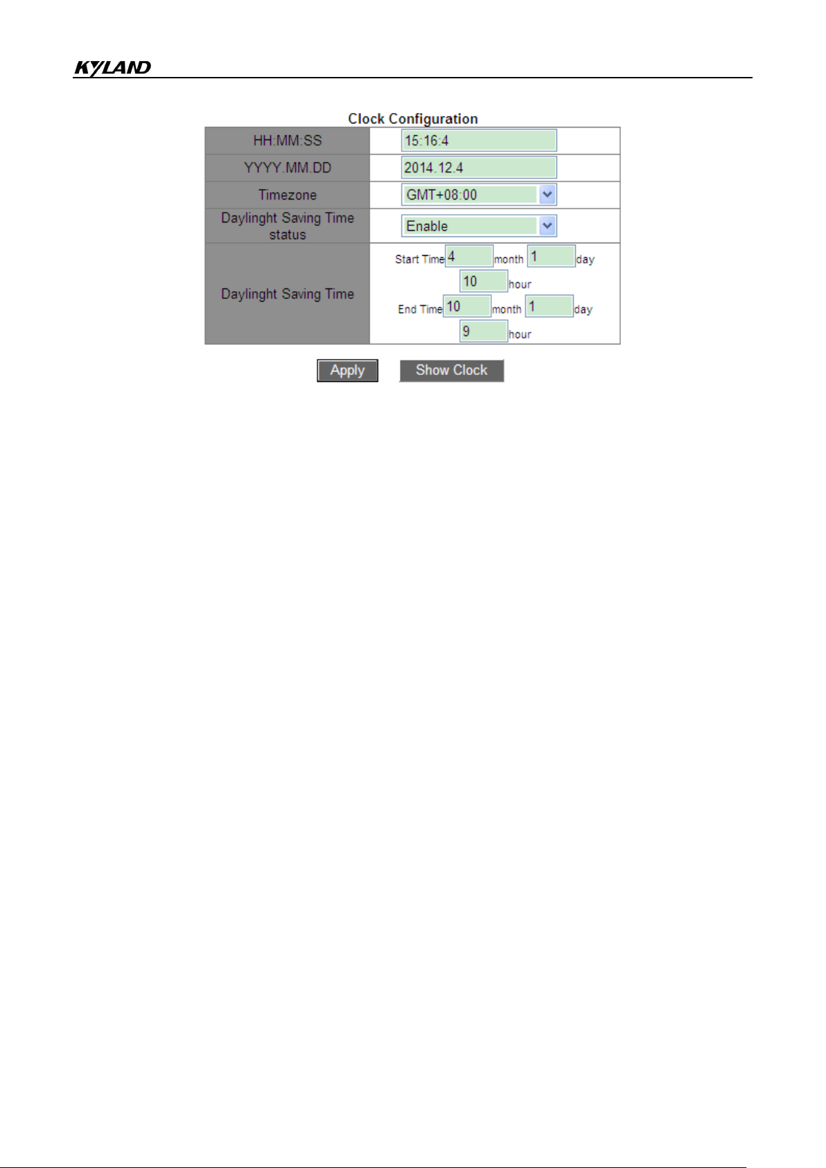
HH:MM:SS
Device Basic Configuration
Figure 23 Clock Configuration
Range: The value of HH ranges from 0 to 23, and that of MM and SS ranges from 0 to 59.
YYYY.MM.DD
Range: The value of YYYY ranges from 1970 to 2099, that of MM from 1 to 12, and that of
DD from 1 to 31.
Description: The range of DD varies with month. For example, the range of DD for March is
from 1 to 31, and that for April is from 1 to 30. You can configure it according to the actual
situation.
Timezone
Function: Select the local timezone.
Daylight Saving Time status
Options: Enable/Disable
Default: Disable
Function: Enable or disable DST. After DST is enabled, clock will be adjusted forward one
hour in summer.
Daylight Saving Time
Configure the time segment for DST.
27

Device Basic Configuration
Caution:
Start time should be different from end time.
Start time indicates non-DST time. End time indicates DST time.
User Level
Description
Guest
The lowest level, guest users can only view switch configuration, but cannot perform
configuration or modification.
Guest users cannot access the following functions: software update, user management,
file transmission, reboot, save current configuration, and load default.
System
Medium level, system users have certain access and configuration rights.
System users cannot access the following functions: software update, user
management, file transmission, reboot, and load default.
Note: System user can modify password of the current user.
Admin
Highest level, admin users have the rights to perform all functions.
For example, run DST from 10:00:00 April 1st to 9:00:00 October 1st.
Non-DST time will run until 10:00:00 April 1st. Then the clock jumps to 11:00:00 to start DST.
DST runs until 9:00:00 October 1st. Then the clock jumps back to 8:00:00 to run non-DST
time.
5.2 User Management Configuration
To avoid security problems caused by illegitimate users, the series switches provide
hierarchical user management. The switches provide different operation rights based on
user levels, satisfying diversified access control requirements. Three user levels are
available, as shown in Table 2.
Table 2 User Level
5.2.1 Web Configuration
1. Configure users
28

Device Basic Configuration
Click [Device Basic Configuration] →[User Configuration]→[User Configuration] to enter
user configuration page, as shown in Figure 24.
Figure 24 User Configuration
Name
Range: 1~16 characters
Service
Options: console/telnet/ssh/web
Function: Select switch access mode for the current user. One or multiple access modes can
be selected.
Level
Option: Guest/System/Admin
Default: Guest
Option: Select user level, users of different levels have different operation rights.
Authen-Type
Option: Password/Key/Password or Key
Default: Password
Function: Selected the authentication type to be used when the current user accesses the
switch. When selecting Password, you must configure the Password option. When
selecting Key, you must configure the Key name option.
Password
Range: 1~32 characters
29

Device Basic Configuration
Note:
Currently, console/telnet/web does not support the key-based authentication mode.
Therefore, when the service type is console/telnet/web, does not select key-based
authentication as the authentication type.
ssh supports two authentication modes, that is, password-based authentication and
key-based authentication.
The switch supports a maximum of nine users.
Default user admin cannot be deleted. The default service (console, telnet, ssh, web) and
level (administration level) of this user cannot be modified, but the default password (123)
can be modified.
For the switch access mode of console/telnet/web, please see the “2 Switch Access” section.
For the switch access mode of ssh, please see the “5.11 SSH Server Configuration” section.
Function: Configure the password to be used when the current user accesses the switch.
Key name
Function: Select the key name to be used when current user accesses the switch in ssh
mode.
2. Modify and delete user information
Click the user entry under user configuration list in Figure 24. You can modify and delete the
user configuration, as shown in Figure 25.
Figure 25 Modify and Delete User Information
3. Configure SSH Key
Click [Device Basic Configuration] →[User Configuration]→[SSH Key Configuration] to
enter SSH key configuration page, as shown in Figure 26.
30

Key Name
Range: 1~16 characters
Key Type
Device Basic Configuration
Figure 26 SSH Key Configuration
Mandatory configuration: RSA
This series switches only support RSA key algorithm.
Key Value
Format: {algorithm name, public key, key info}
Algorithm name: ssh-rsa | ssh-dsa
Public key: it is based on 64 codes and the length is less than 2048 bytes
Key info: more info for the key
Function: Configure the public key corresponding to the client. Generally, the public key is
generated by Puttygen software and is copied to the key value of the server, the private key
is saved in the client.
4. Modify the password of current user
Click [Device Basic Configuration] → [User Configuration]→[Modify Password] to enter
password modification page, as shown in Figure 27.
31

Device Basic Configuration
Figure 27 Modify
New password/Repeat password
Range: 1~32 characters
5. Configure timeouts for switch access modes
Click [Device Basic Configuration] → [User Configuration]→[Timeouts Configuration] to
enter password modification page, as shown in Figure 28.
Figure 28 Timeouts Configuration
Time
Range: 0~44640 min
Default: 5 min for console/ssh/telnet; 10 min for web
Function: Configure the login user timeout and disconnection time. The time starts counting
when a user finishes all configurations, and the system will automatically exit the access
mode when the time ends. When the time is set to 0, the user timeout and disconnection
function is disabled. In this case, the server will not judge whether the user login times out
and therefore the user will not exit the current login mode.
5.3 Port Configuration
5.3.1 Physical Port Configuration
5.3.1.1 Introduction
In physical port configuration, you can configure the cable type, management status,
rate/mode, and other information.
32

Device Basic Configuration
Caution:
The auto option is recommended.
5.3.1.2 Web Configuration
Click [Device Basic Configuration] → [Port configuration] → [Ethernet port configuration] →
[Physical port configuration] to enter the port configuration page, as shown in Figure 29.
Figure 29 Physical Port Configuration
Port
Options: all switch ports
Description: X/Y is the port name format; X is 1 for this switch, and Y is the port number on
the panel.
mdi
Options: auto/normal/across
Default: auto
Function: Configure the cable type for the Ethernet port.
Description: auto means auto-recognition of cable type; across means the port supports only
cross-over cable; normal means the port supports only straight-through cable.
Admin Status
Options: shutdown/no shutdown
Default: no shutdown
Function: Allow data transmission on port or not.
Description: no shutdown indicates the port is enabled and permits data transmission;
shutdown indicates the port is disabled and disallows data transmission. This option directly
affects the hardware status of the port and triggers port alarms.
Speed/duplex status
33

Device Basic Configuration
Caution:
The speed/duplex mode of a 10/100Base-TX port can be set to auto, 10M/Half, 10M/Full,
100M/Half, or 100M/Full.
The speed/duplex mode of a 100Base-FX port can be set to 100M/Full only.
The speed/duplex mode of a 10/100/1000Base-TX port can be set to auto, 10M/Half,
10M/Full, 100M/Half, 100M/Full, 1000M/Half, or 1000M/Full.
The speed/duplex mode of a Gigabit fiber port can be set to auto or 1000M/Full only.
Options: auto, 10M/Half, 10M/Full, 100M/Half, 100M/Full, 1000M/Half, 1000M/Full
Default: auto
Function: Configure the port speed and duplex mode.
Description: Port speed and duplex mode support auto-negotiation and forced configuration.
If it is set to "auto", the port speed and duplex mode will be automatically negotiated
according to port connecting status. When the port duplex mode changes from
auto-negotiation to forced full duplex or half duplex, the port speed will also be changed to
forced mode. It is recommended to set the parameter to auto to avoid the connection
problem caused by unmatched port configuration on both ends of link. If you set the port to
forced speed or duplex, please ensure the speed or duplex mode configurations on both
ends of the connection are the same.
You can view port information based on Ethernet port configuration and communication
conditions, as shown in Figure 30.
Figure 30 Port List
34

Device Basic Configuration
5.3.2 Port Information
Click [Device Basic Configuration] → [Port configuration] → [Port debug and maintenance]
→ [Show port information] to enter the port information page. It contains the port connecting
status, port type, input/output packet statistics, and other information, as shown in Figure 31.
Figure 31 Port Information
5.4 VLAN Configuration
5.4.1 Introduction
One LAN can be divided into multiple logical Virtual Local Area Networks (VLANs). A device
can only communicate with the devices on the same VLAN. As a result, broadcast packets
35

Device Basic Configuration
DA
SA
802.1Q Header
Length/Type
Data
FCS
Type
PRI
CFI
VID
Note:
VLAN 1 is the default VLAN and cannot be manually created and deleted.
Reserved VLANs are reserved to realize specific functions by the system and cannot be
manually created and deleted.
are restricted to a VLAN, optimizing LAN security.
VLAN partition is not restricted by physical location. Each VLAN is regarded as a logical
network. If a host in one VLAN needs to send data packets to a host in another VLAN, a
router or layer-3 device must be involved.
5.4.2 Principle
To enable network devices to distinguish packets from different VLANs, fields for identifying
VLANs need to be added to packets. At present, the most commonly used protocol for VLAN
identification is IEEE802.1Q. Table 3 shows the structure of an 802.1Q frame.
Table 3 802.1Q Frame Structure
A 4-byte 802.1Q header, as the VLAN tag, is added to the traditional Ethernet data frame.
Type: 16 bits. It is used to identify a data frame carrying a VLAN tag. The value is 0x8100.
PRI: three bits, identifying the 802.1p priority of a packet.
CFI: one bit. 0 indicates Ethernet, and 1 indicates token ring.
VID: 12 bits, indicating the VLAN number. The value ranges from 1 to 4093. 0, 4094, and
4095 are reserved values.
The packet containing 802.1Q header is a tagged packet; the one without 802.1Q header is
an untagged packet. All packets carry an 802.1Q tag in the switch.
5.4.3 Port-based VLAN
VLAN partition can be either port-based or MAC address-based. This series switches
support port-based VLAN partition. VLAN members can be defined based on switch ports.
36

Device Basic Configuration
Processing Received Packets
Processing Packets to Be Forwarded
Untagged packets
Tagged packets
Port Type
Packet Processing
Add PVID tags to
packets.
If the VLAN ID in a
packet is in the list of
Untag
Forward the packet after
removing the tag.
After a port is added to a specified VLAN, the port can forward the packets with the tag for
the VLAN.
1. Port Type
Ports fall into two types according to how they handle VLAN tags when they forward packets.
Untag port: Packets forwarded by an Untag port do not have VLAN tags. Untag ports are
usually used to connect to terminals that do not support 802.1Q. By default, all switch
ports are Untag ports and belong to VLAN1.
Tag port: All packets forwarded by a Tag port carry a VLAN tag. Tag ports are usually
used to connect network transmission devices.
2. Port Mode
Access: In access mode, the port must be untag and added to one VLAN; the port
cannot be tag and added to any VLAN.
Trunk: In trunk mode, the port must be untag and added to the PVID VLAN; the port can
be tag/untag and added to any other VLAN.
3. PVID
Each port has a PVID. When receiving an untagged packet, a port adds a tag to the packet
according to the PVID. The default PVID of all ports is 1.
The PVID of an Access port is the ID of VLAN that the port belongs to, and it cannot be
configured.
The PVID of a Trunk port can be configured as one of the VLAN IDs allowed through the
port.
Table 4 shows how the switch processes received and forwarded packets according to the
port mode, port type and PVID.
Table 4 Different Processing Modes for Packets
37

Device Basic Configuration
VLANs allowed through,
accept the packet.
If the VLAN ID in a
packet is not in the list of
VLANs allowed through,
discard the packet.
Tag
Keep the tag and forward the
packet.
5.4.4 Web Configuration
1. Create or delete a VLAN.
Click [Device Basic Configuration] → [VLAN configuration] → [VLAN configuration] →
[Create/Remove VLAN] → [VLAN ID allocation] to enter the VLAN configuration page, as
shown in Figure 32.
Figure 32 Creating/Deleting a VLAN
VLAN ID
Range: 2~4093. The default VLAN ID is 1.
Function: Use different VLAN IDs to distinguish VLANs.
Description: The series switches support a maximum of 4093 VLANs.
Method: Click <Add> to create a VLAN; click <Remove> to delete the specified VLAN.
2. Configure a VLAN name.
Click [Device Basic Configuration] → [VLAN configuration] → [VLAN configuration] →
[Create/Remove VLAN] → [VLAN ID attribution configuration] to enter the VLAN name
configuration page, as shown in Figure 33.
38

Figure 33 VLAN Configuration
VLAN ID
Range: all created VLANs
Function: Input the ID of the VLAN whose name is to be modified.
VLAN Name
Range: 1~11 characters
Device Basic Configuration
Function: Input the name of the VLAN with the specified ID.
VLAN Type
Options: universal
Default: universal
After setting is completed, the "VLAN ID Information" page lists the attribute information of all
created VLANs, as shown in Figure 34.
Figure 34 VLAN List
3. Configure port mode
Click [Device Basic Configuration] → [VLAN configuration] → [VLAN configuration] → [Port
type configuration] → [Set port mode (Trunk/Access)] to enter the port type configuration
page, as shown in Figure 35.
39

Device Basic Configuration
Figure 35 Port Type Configuration
Port
Options: all switch ports
Type
Options: access/trunk
Default: access
Function: Select the mode for the specified port. Each port supports only one mode.
After setting is completed, the "Port mode configuration" page lists all port types, as shown in
Figure 36.
Figure 36 Port Type Information
4. Allocate ports to the created VLANs.
Click [Device Basic Configuration] → [VLAN configuration] → [VLAN configuration] →
[Allocate ports for VLAN] → [Allocate ports for VLAN] to enter the Access port VLAN
configuration page, as shown in Figure 37.
40

Device Basic Configuration
Caution:
In access mode, the port must be untag and added to one VLAN.
In trunk mode, the port must be untag and added to the PVID VLAN; the port can be
tag/untag and added to any other VLAN.
Figure 37 Allocating Access Ports to VLANs
Tag Type
Option: Tag/Untag
Function: Select the type of the port to be added to the VLAN.
5. Configure the PVID for a Trunk port.
Click [Device Basic Configuration] → [VLAN configuration] → [VLAN configuration] → [Trunk
port configuration] → [VLAN setting for trunk port] to enter the Trunk port VLAN configuration
page, as shown in Figure 38.
41

Figure 38 Trunk Port PVID Configuration
Trunk Port
Options: all Trunk ports
Trunk Native VLAN (pvid)
Options: all created VLANs
Default: 1
Function: Configure the PVID for a Trunk port.
Device Basic Configuration
Description: No matter whether a port does not exist in a VLAN or exists in a VLAN in the
form of Untag/tag, after the PVID is specified, this port will be added to the VLAN in the form
of Untag.
Method: Click <Default> to restore the PVID of selected Trunk port to 1.
6. Configure VLANs for a Trunk port, as shown in Figure 39.
Figure 39 Configuring VLANs for a Trunk Port
Trunk Port
Options: all Trunk ports
Tag Type
Option: Tag/Untag
Function: Select the type of the trunk port to be added to the VLAN.
Trunk Allow VLAN List
Options: all created VLANs
42

Device Basic Configuration
Default: all created VLANs
Function: Configure VLANs for the selected Trunk port.
After setting is completed, the VLAN information of all Trunk ports is displayed, as shown in
Figure 40.
Figure 40 VLAN Configuration of Trunk Ports
7. Configure VLAN ingress rule for a port.
Click [Device Basic Configuration] → [VLAN configuration] → [VLAN configuration] →
[Enable/Disable VLAN ingress rule] → [Enable/Disable VLAN ingress rule] to enter the
VLAN ingress rule configuration page, as shown in Figure 41.
Figure 41 Configuring VLAN Ingress Rule
Options: Enable/Disable
Default: Enable
Function: Enable or disable the VLAN ingress rule for a port.
Description: If this function is enabled, the port checks the VLAN ID of a packet against its
allowed VLAN list upon receiving the packet. If a match is found, the port forwards the
packet; otherwise, the packet is discarded. If this function is disabled, the port forwards all
packets without checking their VLAN IDs.
After setting is completed, all VLAN ingress rules information is displayed, as shown in
Figure 42.
43

Device Basic Configuration
Figure 42 VLAN Ingress Rule Information
8. Configure VLAN-aware
Click [Device Basic Configuration] → [VLAN configuration] → [VLAN configuration] →
[VLAN-aware] → [VLAN-aware] to enter the VLAN ingress rule configuration page, as shown
in Figure 43.
Figure 43 VLAN-aware Configuration
Option: Aware/Unaware
Default: Aware
Function: When Aware is selected, the device identifies and judges the VLAN according to
the IEEE802.1Q protocol and forwards packets properly. When Unaware is selected, the
device does not judge the VLAN ID of an unknown unicast packet and forwards the packet to
any port (broadcast); the device does not judge the VLAN ID of a known unicast packet and
forwards the packet to a relevant port according to the MAC address table.
9. View the information about all created VLANs.
Click [Device Basic Configuration] → [VLAN configuration] → [VLAN debug and
maintenance] → [Show VLAN] to enter the VLAN information page, as shown in Figure 44.
44

Figure 44 VLAN Information
VLAN
Configuration
VLAN2
Set port 1/1 and port 1/2 of Switch A and B to untag ports, and port 1/7 to tag port.
VLAN100
Set port 1/3 and port 1/4 of Switch A and B to untag ports, and port 1/7 to tag port.
VLAN200
Set port 1/5 and port 1/6 of Switch A and B to untag ports, and port 1/7 to tag port.
Device Basic Configuration
5.4.5 Typical Configuration Example
As shown in Figure 45, the entire LAN is divided into 3 VLANs: VLAN2, VLAN100, and
VLAN200. It is required that the devices in the same VLAN can communicate with each
other, but different VLANs are isolated. The terminal PCs cannot distinguish tagged packets,
so the ports connecting Switch A and Switch B with PCs are set to access port. VLAN2,
VLAN100, and VLAN200 packets need to be transmitted between Switch A and Switch B, so
the ports connecting Switch A and Switch B should be set to trunk port, permitting the
packets of VLAN 2, VLAN 100, and VLAN 200 to pass through. Table 5 shows specific
configuration.
Table 5 VLAN Configuration
45

Device Basic Configuration
Figure 45 VLAN Application
Configurations on Switch A and Switch B:
1. Create VLAN2, VLAN100, and VLAN200, as shown in Figure 32.
2. Configure ports 1/1, 1/2, 1/3, 1/4, 1/5, 1/6 as Access ports, and port 1/7 as Trunk port, as
shown in Figure 35.
3. Add ports 1/1 and 1/2 to VLAN2 as untag ports; ports 1/3 and 1/4 to VLAN100 as untag
ports; ports 1/5 and 1/6 to VLAN200 as untag ports; port 1/7 to VLAN2, VLAN100, VLAN200
as tag port, as shown in Figure 37.
5.5 PVLAN Configuration
5.5.1 Introduction
PVLAN (Private VLAN) uses two layers isolation technologies to realize the complex port
traffic isolation function, achieving network security and broadcast domain isolation.
The upper VLAN is a shared domain VLAN in which ports are uplink ports. The lower VLANs
are isolation domains in which ports are downlink ports. Downlink ports can be assigned to
different isolation domains and they can communicate with uplink port at the same time.
Isolation domains cannot communicate to each other.
46

Device Basic Configuration
Figure 46 PVLAN Application
As shown in Figure 46, the shared domain is VLAN100 and the isolation domains are VLAN
10 and VLAN 30; the devices in the isolation domains can communicate with the device in
the share domain, such as VLAN 10 can communicate with VLAN 100; VLAN 30 can also
communicate with VLAN 100, but the devices in different isolation domains cannot
communicate with each other, such as VLAN 10 cannot communicate with VLAN 30.
5.5.2 Explanation
PVLAN function can be implemented through special configuration on ports.
The PVID of uplink ports are the same as shares domain VLAN ID; the PVID of downlink
ports are the same as their own isolation domain VLAN ID.
The uplink ports are set to untag and are assigned to the shares domain VLAN and all
isolation domains; the downlink ports are set to untag and are assigned to the shared
domain VLAN and own isolation domain.
5.5.3 Typical Configuration Example
Figure 47 shows PVLAN application. VLAN300 is a shared domain and port 1 and port 2 are
uplink ports; VLAN100 and VLAN200 are isolation domains and ports 3, 4, 5, and 6 are
downlink ports.
47

Device Basic Configuration
Figure 47 PVLAN Configuration Example
Switch configuration:
1. Create VLAN300, VLAN 100, and VLAN 200, as shown in Figure 32.
2. Configure ports 1, 2, 3, 4, 5, 6 as trunk ports, as shown in Figure 35.
3. Add ports 1~6 to VLAN300 as untag ports; ports 1~4 to VLAN100 as untag ports; ports 1,
2, 5, 6 to VLAN200 as untag ports, as shown in Figure 37.
4. Configure the PVID of ports 1 and 2 to 300; the PVID of ports 3 and 4 to 100; the PVID of
ports 5 and 6 to 200, as shown in Figure 38.
5.6 Port Mirroring
5.6.1 Introduction
With port mirroring function, the switch copies all received or transmitted data frames in a
port (mirroring source port) to another port (mirroring destination port). The mirroring
destination port is connected to a protocol analyzer or RMON monitor for network monitoring,
management, and fault diagnosis.
48

Device Basic Configuration
Caution:
Mirroring destination port and port channel are mutually exclusive. The mirroring destination
port cannot be added to a port channel, and the port in a port channel cannot be set to a
mirroring destination port.
5.6.2 Explanation
A switch supports only one mirroring destination port but multiple source ports.
Multiple source ports can be either in the same VLAN, or in different VLANs. Mirroring
source port and destination port can be in the same VLAN or in different VLANs.
The source port and destination port cannot be the same port.
5.6.3 Web Configuration
1. Select the mirroring source port and mirroring mode.
Click [Device Basic Configuration] → [Port mirroring configuration] → [Mirror configuration]
to enter the mirroring source port configuration page, as shown in Figure 48.
Figure 48 Mirroring Source Port Configuration
Session
Option: 1~7
Default: 1
Function: Select a mirroring group.
Mirror Direction
Options: rx/tx/both
Default: both
Function: Select the data to be mirrored in the mirroring source port.
49
Device Basic Configuration
Description: rx indicates only the received packets are mirrored in the source port.
tx indicates only the transmitted packets are mirrored in the source port.
Both indicates both transmitted and received packets are mirrored in the source port.
Source port
Options: all switch ports
Function: Select the mirroring source port. You can select multiple source ports.
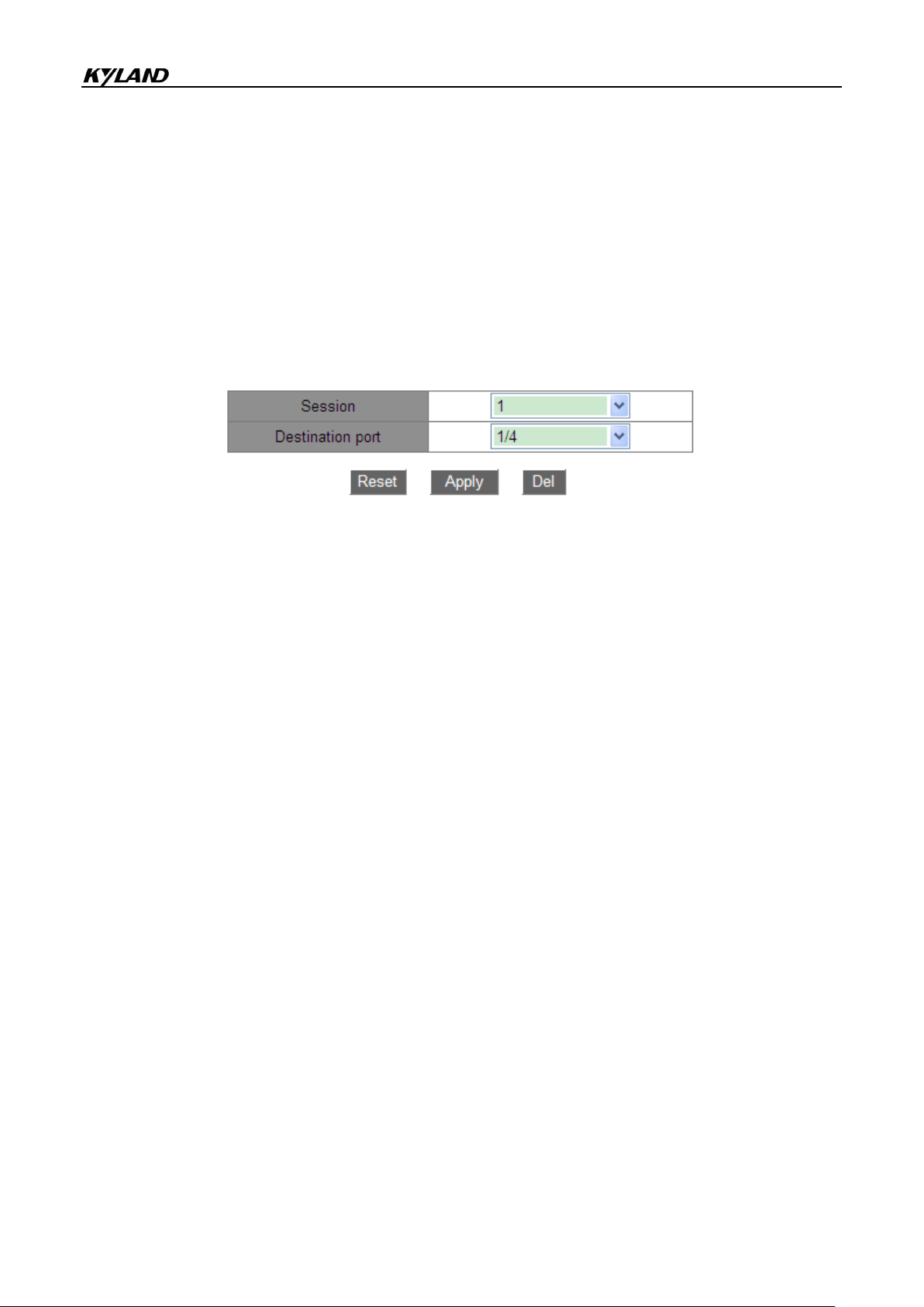
2. Select the mirroring destination port, as shown in Figure 49.
Figure 49 Mirroring Destination Port Configuration
Session
Option: 1~7
Default: 1
Function: Select a mirroring group.
Destination port
Options: all ports other than the source port
Function: Select the mirroring destination port.
Description: Set a port to a mirroring destination port. There is only one mirroring destination
port. The mirroring destination port cannot be a member of a port channel. It is better that the
throughput of the destination port is larger than or equal to the total throughputs of its source
ports.
5.6.4 Typical Configuration Example
As shown in Figure 50, the mirroring destination port is port 2 and the mirroring source port
is port 1. Both transmitted and received packets on port 1 are mirrored to port 2.
50

Device Basic Configuration
Figure 50 Port Mirroring Example
Configuration process:
1. Set port 2 to the mirroring destination port, as shown in Figure 49.
2. Set port 1 to the mirroring source port and the port mirroring mode to both, as shown in
Figure 48.
5.7 Port Storm Control
5.7.1 Introduction
Port storm control is to limit the port-received broadcast/multicast/unknown unicast packets.
When the rate of broadcast/multicast/unknown unicast packets received on the port exceeds
the configured threshold, the system will discard excess broadcast/multicast/unknown
unicast packets to keep the broadcast/multicast/unknown unicast traffic within the allowable
range, ensuring normal network operation.
5.7.2 Web Configuration
1. Configure the port storm control threshold.
Click [Device Basic Configuration] → [Port Storm Suppression configuration] → [Port Storm
Suppression configuration] to enter the configuration page, as shown in Figure 51.
Figure 51 Port Storm Control Threshold Configuration
51

Device Basic Configuration
Port Rate
Threshold Unit
Step
Value Range
10M
bps
512
512~10000000
kbps
Not recommended
Not recommended
100M
bps
5120
5120~100000000
kbps
5
5~100000
1000M
bps
51200
51200~1000000000
kbps
50
50~1000000
Port name
Options: all switch ports
Function: Select the ports that need rate limiting.
Rate Unit:
Options: bps/kbps/percent
Function: Select the unit of the threshold.
Rate Value:
Range: 1~1000000kbps/1~1000000000bps/1~100 Percent
Default: 0, when the value is 0, port storm control is disabled.
Function: Configure the threshold for port rate limiting and the packets that exceed the
threshold will be dropped. The value range depends on the actual port speed. For details,
see Table 6.
Description: The threshold of Fast Ethernet port is in the range of
1~100000kbps/1~100000000bps; the threshold of Gigabit Ethernet port is in the range of
1~1000000kbps/1~1000000000bps. Percent corresponds to the port bandwidth, for
example, if the rate limiting value of a 100M port is 60%, the port begins to discard data after
receiving 60M data traffic.
Table 6 Value Range of Port Rate Threshold
2. Select the type of packets to be controlled, as shown in Figure 52.
52

Figure 52 Configuring the Packets to Be Controlled
Note:
On each port, only one threshold can be configured. The threshold takes effect on the
configured packet type.
Port name
Options: all ports on which port storm control is enabled
Suppression Type
Options: Multicast/broadcast/dlf
Function: Select the type of packets to be controlled.
Function
Options: Enable/Disable
Device Basic Configuration
Default: Disable
Function: Enable or disable the control on the type of packets.
5.7.3 Typical Configuration Example
Enable the unknown multicast storm control on port 1/1 with the bandwidth threshold of
1000kbps.
Configuration process:
1. Select port 1/1 and set rate unit to kbps and rate value to 1000kbps, as shown in Figure
51.
2. Set packet type to multicast, as shown in Figure 52.
5.8 Port Isolation
5.8.1 Introduction
To implement isolation of packets on layer 2, you can add ports to different VLANs. However,
53

Device Basic Configuration
Note:
Ports of the isolation group can only be ports from the same switch.
One device supports a maximum of 14 isolation groups, and there is no limit to the number
of Ethernet ports in each group.
Following the configuration of the isolation group, only the packets among the ports of the
isolation group could not exchange with each other, the communication between the ports
within the isolation group and the ports outside the isolation group would not affected.
Isolated port and port channel are mutually exclusive. The port of isolation group cannot be
added to a port channel, and the port in a port channel cannot be added to an isolation
group.
this method will cause a waste of limited VLAN resources. By adopting the port isolation
feature, you can isolate ports in the same VLAN from each other. User only needs to add
port to isolation group, and the isolation of data in layer 2 among ports of the isolation group
would be realized because the ports in the isolation group would not forward packets to other
ports of the isolation group. The port isolation function provides users with a more secure
and flexible networking solution.
5.8.2 Web Configuration
Enable the port isolation, as shown in Figure 53.
Figure 53 Port Isolation Configuration
Port isolate
Options: Enable/Disable
Default: Disable
54

Device Basic Configuration
Caution:
One port is added to only one isolation group.
Function: Enable or disable the port isolate.
5.8.3 Typical Configuration Example
Connect PC1, PC2, and PC3 to the Ethernet port 1, 2, and 3 of the switch, and connect port
4 to the external network. Ports 1, 2, 3, and 4 are in the VLAN 1. PC1, PC2, and PC3 cannot
communicate with each other, but they can access the external network, as shown in Figure
54.
Figure 54 Port Isolation configuration Instance
Add port 1, 2, and 3 to the isolation group to isolate PC1, PC2, and PC3, as shown in Figure
53.
5.9 Port Channel
5.9.1 Introduction
Port channel is to bind a group of physical ports that have the same configuration to a logical
port to increase bandwidth and improve transmission speed. The member ports in a same
group share traffic and serve as dynamic backups for each other, improving connection
55

Device Basic Configuration
reliability.
Port group is a physical port group on the configuration layer. Only the physical ports that
join in port group can participate in link aggregation and become a member of port channel.
When physical ports in a port group meet certain conditions, they can conduct port
aggregation and form a port channel and become an independent logical port, thereby
increasing network bandwidth and providing link backup.
5.9.2 Implementation
As shown in Figure 55, three ports on Switch A and Switch B aggregate to form a port
channel. The bandwidth of the port channel is the total bandwidth of these three ports.
Figure 55 Port Channel
If Switch A sends packets to Switch B by way of the port channel, Switch A determines the
member port for transmitting the traffic based on the calculation result of load sharing. When
one member port of the port channel fails, the traffic transmitted through the port is taken
over by another normal port based on load sharing algorithm.
5.9.3 Explanation
The series switches support a maximum of 8 port groups and each group contains a
maximum of 8 member ports.
56

Device Basic Configuration
Caution:
A port can be added to only one port group.
Port channel and isolated port are mutually exclusive. The port in a port channel cannot be
added to an isolation group; the port of isolation group cannot be added to a port channel.
Port channel and mirroring destination port are mutually exclusive. The port in a port channel
cannot be configured as a mirroring destination port; the mirroring destination port cannot be
added to a port channel.
5.9.4 Web Configuration
1. Configure load sharing mode of port channel.
Click [Device Basic Configuration] → [Port channel configuration] → [LACP port group
configuration] to enter the configuration page, as shown in Figure 56.
Figure 56 Load Sharing Mode Configuration
Load balance mode
Options: mac-only/ip-only/mac-ip/ip-l4/mac-ip-l4
Default: mac-only
Function: Set the load sharing mode of port channel.
Description: mac-only indicates MAC address-based load sharing.
ip-only indicates IP address-based load sharing.
mac-ip indicates load sharing based on MAC address and IP address.
ip-I4 indicates load sharing based on IP address and TCP/UDP port number.
mac-ip-14 indicates load sharing based on MAC address, IP address, and TCP/UDP port
number.
Explanation: If load sharing mode needs to be changed after a port channel is formed, the
change will take effect after the next aggregation.
57

Device Basic Configuration
2. Create or delete a port group, as shown in Figure 57.
Figure 57 Port Channel Configuration
LACP group number
Range: 1~8
Function: Set the port group number with a maximum of 8 port groups.
Operation type
Options: add port group/remove port group
Default: add port group
Function: Create or delete a port group.
After setting is completed, the "port group table" page lists all created port groups and load
sharing modes, as shown in Figure 58.
Figure 58 Port Group List
3. Configure a port group member.
Click [Device Basic Configuration] → [Port channel configuration] → [LACP port
configuration] to enter the configuration page, as shown in Figure 59.
Figure 59 Port Group Member Configuration
58

Device Basic Configuration
LACP group number
Options: all created port group numbers
Port
Options: all switch ports
Function: Select the port to be added to or deleted from a port group.
Description: The member ports in a same port group have the same port attributes.
Operation type
Options: Add port to group/Remove port from group
Default: Add port to group
Function: Add a port to or remove a port from a port group.
5.9.5 Typical Configuration Example
As shown in Figure 55, add three ports (port 1, 2, and 3) of Switch A to port group 1 and
three ports (port 1, 2, and 3) of switch B to port group 2. Use network cables to connect
these ports to form a port channel, realizing load sharing among ports. (It is assumed that
the three ports on Switch A and B have the same attributes respectively.)
Configuration on switches:
1. Add port group 1 on Switch A, as shown in Figure 57.
2. Add port 1, 2, and 3 to port group 1, as shown in Figure 58.
3. Add port group 2 on Switch B, as shown in Figure 57.
4. Add port 1, 2, and 3 to port group 2, as shown in Figure 58.
5.10 Telnet Server Configuration
5.10.1 Introduction
Telnet is a protocol for accessing remote terminals. You can log in to a remote host by using
the IP address or host name through Telnet. Telnet can transmit your commands to the
remote host and return the output of the remote to your display through TCP.
Telnet adopts the client/server mode. The local system is the client, while the remote host is
59

Device Basic Configuration
Note:
The switch can work as a Telnet client to log in to a remote host regardless of whether the
function is enabled.
the server. This series switches can serve as a Telnet server or client.
When a switch serves as a Telnet server, you can log in to the switch by using the Telnet
client software in the Windows or other OSs. When the switch serves as a Telnet server, it
can establish TCP connections with a maximum of 5 Telnet clients.
When the switch serves as a Telnet client, you can use Telnet commands in the general view
to log in to other remote hosts. When serving as a Telnet client, the switch can establish TCP
connection with only one remote host. To establish TCP connection with another host, the
switch must disconnect the connected host first.
5.10.2 Web Configuration
1. Enable the Telnet server function.
Click [Device Basic Configuration] → [Telnet server configuration] → [Telnet server user
configuration] to enter telnet server configuration page, as shown in Figure 60.
Figure 60 Telnet Server Configuration
Telnet server state
Configuration items: open/close
Default: open
Function: Enable or disable the Telnet server function.
Description: Open means that Telnet clients can log in to the switch. Close means that Telnet
clients cannot log in to the switch.
2. Configure security IP address for Telnet client login.
60

Device Basic Configuration
Click [Device Basic Configuration] → [Telnet server configuration] → [Telnet security IP] to
enter security IP address configuration page, as shown in Figure 61.
Figure 61 Telnet Server Security IP
Security IP address
Format: A.B.C.D
Function: Configure security IP address for Telnet client login when the switch works as a
Telnet server.
Description: If the security IP is not set, there is not restriction on Telnet client's IP address.
After the security IP addresses are set, only the client with a security IP address can log in to
and configure the switch by Telnet.
A switch allows a maximum of 32 security IP addresses. By default, no security IP address is
configured.
After setting is completed, the "Telnet server Security IP list" displays Telnet client IP
addresses that can log in to the switch, as shown in Figure 62.
Figure 62 Security IP Address List
5.11 SSH Server Configuration
5.11.1 Introduction
SSH (Secure Shell) is a network protocol for secure remote login. It encrypts all transmitted
data to prevent information disclosure. When data is encrypted by SSH, users can only use
61

Device Basic Configuration
command lines to configure switches.
The switch supports the SSH server function and allows the connection of multiple SSH
users that log in to the switch remotely through SSH, but a maximum of two users can
connect to the switch at a time.
5.11.2 Secret Key
The unencrypted message is called plaintext, and the encrypted message is called cipher
text. Encryption or decryption is under the control of the secret key. A secret key is a specific
character string and is the only parameter to control the transformation between plain text
and cipher text, working as a Key. Encryption can change plain text to cipher text, while
decryption can change cipher text to plain text.
The key-based security authentication needs secret keys, and each end of the
communication has a pair of secret keys, private key and public key. Public key is used to
encrypt data, and the legal owner of private key can use the private key to decrypt the date
to guarantee the data security.
5.11.3 Implementation
In order to realize the SSH secure connection in the communication process, the server and
the client experience the following five stages:
Version negotiation stage: currently, SSH consists of two versions: SSH1 and SSH2. The
two parties negotiate a version to use.
Key and algorithm negotiation stage: SSH supports multiple types of encryption algorithms.
The two parties negotiate an algorithm to use.
Authentication state: the SSH client sends an authentication request to the server and the
server authenticates the client.
Session request stage: the client sends a session request to the server after passing the
authentication.
Session stage: the client and the server start communication after passing the session
request.
62

Device Basic Configuration
5.11.4 Web Configuration
SSH server configuration steps:
Click [Device Basic Configuration] → [SSH Server Configuration] → [SSH server
configuration] to enter the SSH server configuration page.
1. Disable SSH status.
2. Click <Destroy> to destroy the old key pair, as shown in Figure 63.
Figure 63 Destroy the Old Key Pair
3. Click <Create> to create a new key pair.
4. Enable SSH protocol and configure the SSH server, as shown in Figure 64.
Server state
Figure 64 SSH Server Configuration
63

Device Basic Configuration
Option: Open/Close
Default: Close
Function: Enable/Disable SSH protocol. If it is enabled, the switch works as the SSH server.
Authentication Retry Times
Configuration range: 1~10
Default: 10
Function: set the number of attempts to log into SSH server.
Local Key Pair
Configuration options: Create/Destroy
Function: create or destroy the local key pair of the SSH server. Please create a local key
pair before enabling SSH server; destroy the old key pair before creating a new key pair.
Local Key Value
Function: show the local key value. Click <Create> to automatically generate the key value.
Configure security IP address for SSH client login.
Click [Device Basic Configuration] → [SSH Server Configuration] → [SSH security IP] to
enter security IP address configuration page, as shown in Figure 65.
Figure 65 SSH Sever Security IP Configuration
Security IP Address
Format: A.B.C.D
Function: Configure security IP address for SSH client login when the switch works as a
SSH server. If the security IP is not set, there is not restriction on SSH client's IP address.
After the security IP addresses are set, only the client with a security IP address can log in to
64

Device Basic Configuration
and configure the switch by SSH.
Explanation: A switch allows a maximum of 6 security IP addresses. By default, no security
IP address is configured.
5.11.5 Typical Configuration Example
The Host works as the SSH client to establish a local connection with switch, as shown in
Figure 66.
Figure 66 SSH Configuration Example
SSH user chooses the authentication type of “password”.
1. Destroy the old key pair of the server, create a new key pair and start SSH server, see
Figure 63, Figure 64.
2. Set SSH user name to 333, service to SSH, authen-type to password, password to 333,
see Figure 24.
3. Establish the connection with the SSH server. First, run the PuTTY.exe software, as
shown in Figure 67; input the IP address of the SSH server "192. 168.0.2" in the space of
Host Name (or IP address).
65

Device Basic Configuration
Figure 67 SSH Client Configuration
4. Click <Open> button and following warning message appears shown in Figure 68, click
the <是(Y)> button.
Figure 68 Warning Message
66

Device Basic Configuration
5. Input the user name "333" and the password "333" to enter the switch configuration
interface, as shown in Figure 69.
Figure 69 Login Interface of the SSH Password Authentication
SSH user chooses the authentication type of "Key".
1. Destroy the old key pair of the server, create a new key pair and start SSH server, see
Figure 63, Figure 64.
2. Configure SSH client, see Figure 26, run PuTTYGen.exe in the client, click <Generate>
button to generate the client key pair, as shown in Figure 70.
67

Device Basic Configuration
Figure 70 Generate the Client Key
3. In the generation process, please move the mouse in the screen, otherwise, the progress
bar does not move forward and the generation stops, as shown in Figure 71.
68

Device Basic Configuration
Figure 71 Key Generation
4. As Figure 72 shows, click <Save private key> to save the private key as 444.ppk, and
copy the public key to the space of Key Value in the SSH Key Configuration interface and
input the key name 444, as shown in Figure 26.
69

Device Basic Configuration
Figure 72 Generate the Key Value
5. Set SSH user name to 444, service to SSH, authen-type to key, key name to 444, see
Figure 24
6. Establish a connection with the SSH server. First, run the PuTTY.exe software, as shown
in Figure 73; input the IP address of the SSH server "192.168.0.2" in the space of Host
Name (or IP address).
70

Device Basic Configuration
Figure 73 SSH Client Configuration of the “key” Authentication
7. Click [SSH] →[Auth] in the left side of the Figure 73, and the screen shown in Figure 74
appears, click <Browse> and choose the private file saved in the step 4.
71

Device Basic Configuration
Figure 74 Choose the Key File
8. Click <Open> button; input the user name to enter the switch configuration interface, as
shown in Figure 75.
72

Device Basic Configuration
Figure 75 Login Interface of the SSH Public Key Authentication
5.12 SSL Configuration
5.12.1 Introduce
SSL (Secure Socket Layer) is a security protocol and provides the security link for the
TCP-based application layer protocol, such as HTTPS. SSL encrypts the network
connection at the transport layer and uses the symmetric encryption algorithm to guarantee
the data security, and uses the secret key authentication code to ensure the information
reliability. This protocol is widely used in Web browser, receiving and sending emails,
network fax, real time communication, and so on, providing an encryption protocol for the
security transmission in the network.
Once a switch enables SSL, users must use the secure link https, such as
https://192.168.0.2, to access the switch.
5.12.2 Web Configuration
1. Enable HTTPS protocol
73

Device Basic Configuration
Caution:
The default certificate and private key provided by the company have already been imported to
the switch. Users can enable SSL protocol directly and access the switch in HTTPS mode.
Click [Device Basic Configuration] → [SSH configuration] → [SSH Configuration] to enter the
SSL configuration page, as shown in Figure 76.
Figure 76 Enable HTTPS Protocol
Server state
Option: Enable/Disable
Default: Disable
Function: Enable or disable the SSL protocol.
Explanation: After enabling SSL, users must use the secure link https://ip address to access
the switch.
Certificate/Private key
Function: Input correct certificate and private key, then click <Add> button to import them to
switch.
2. Input the username and password to successfully log into switch through HTTPS.
74

Device Basic Configuration
5.13 File Transmission Service
File transmission service enables mutual file backup between the server and the client.
When a file on the server (or client) is changed, you can obtain the backup file from the client
(or server) through FTP or TFTP.
The switch can serve as the client or server to upload and download files through FTP or
TFTP.
5.13.1 TFTP Service
1. The switch works as the TFTP client.
First, install TFTP server, as shown in Figure 77. In Current Directory, browse the file
storage path in use. Input the server IP address in Server interface.
Figure 77 TFTP Server Configuration
Click [Device Basic Configuration] → [File transmit] → [TFTP Service] → [TFTP client
service] to enter TFTP client configuration page, as shown in Figure 78.
75

Figure 78 TFTP Client Service
Server IP address
Format: A.B.C.D
Description: Input the server IP address.
Local file name
Device Basic Configuration
Range: 1~100 characters
Description: Input the file name of the switch.
Server file name
Range: 1~100 characters
Description: Input the file name of the server.
Transmission type:
Configuration items: binary/ascii
Default: binary
Function: Select the file transmission standard.
Explanation: ascii means using ASCII standard to transmit file; binary means using binary
standard to transmit file.
Method: Click <Upload to PC> to upload the file from switch to server or <Download to
Device> to download file from server to switch.
When file transmission succeeds, the following information appears on the Web
interface, as shown in Figure 79 and Figure 80.
76

Figure 79 Successful File Upload through TFTP
Caution:
In the file transmission process, keeps the TFTP server running.
Software version file is not a text file, and it must adopt the binary standard for transmission
Figure 80 Successful File Download through TFTP
Device Basic Configuration
2. The switch works as the TFTP server.
Click [Device Basic Configuration] → [File transmit] → [TFTP Service] → [TFTP server
service] to enter the TFTP server configuration page, as shown in Figure 81.
Figure 81 TFTP Server Service
Server state
Configuration items: Close/Open
Default: Close
Function: Enable/Disable the TFTP server function.
TFTP Timeout
77

Device Basic Configuration
Caution:
During file transmission, keep TFTP client software running.
Range: 5~3600s
Default: 20s
Function: Configure the timeout of TFTP server connection.
TFTP Retransmit times
Range: 1~20
Default: 5
Function: Configure the retransmission times of TFTP server during timeout.
Install TFTP client software, as shown in Figure 82. Input switch IP address in Host; select
the client file storage path in Local File; input the file name saved in switch in Remote File;
click <Get> to download file from switch to client; click <Put> to upload client file to switch.
Figure 82 TFTP Client Configuration
5.13.2 FTP Service
1. The switch works as the FTP client.
First, install FTP server. Click [Security] → [users/rights] to open the dialog box. Click
<new user> to create a new FTP user, as shown in Figure 83. Input username and
78

Device Basic Configuration
password, for example, username: admin; password: 123. Click <OK>.
Figure 83 Creating a New FTP User
Input the file storage path in server in Home Directory, as shown in Figure 84. Click
<Done>.
79

Device Basic Configuration
Figure 84 File Storage Path
Click [Device Basic Configuration] → [File transmit] → [FTP Service] → [FTP client
service] to enter FTP client configuration page, as shown in Figure 85.
Figure 85 FTP Client Service
Server IP address
Format: A.B.C.D
Description: indicates the server IP address.
{User name, Password}
Range: {1~100 characters, 1~100 characters}
Description: indicates the username and password created on FTP server.
Local file name:
Range: 1~100 characters
Description: indicates the file name in switch.
Server file name
Range: 1~100 characters
Description: indicates the file name in server.
Transmission type:
Configuration items: binary/ascii
Default: binary
Function: Select the file transmission standard.
80

Device Basic Configuration
Caution:
In the file transmission process, keep FTP server software running.
Software version file is not a text file, and it must adopt the binary standard for transmission.
Explanation: ascii means using ASCII standard to transmit file; binary means using binary
standard to transmit file.
Method: Click <Upload to PC> to upload the file from switch to server. Click <Download to
Device> to download file from server to switch.
When file transmission succeeds, the following information appears on the Web interface,
as shown in Figure 86 and Figure 87.
Figure 86 Successful File Upload through FTP
Figure 87 Successful File Download through FTP
2. The switch works as an FTP server.
Click [Device Basic Configuration] → [File transmit] → [FTP Service] → [FTP server
service] to enter FTP server configuration page, as shown in Figure 88.
81

Figure 88 TFTP Server Service
FTP Server state
Options: Close/open
Default: close
Function: Enable or disable the FTP server function.
FTP Timeout
Range: 5~3600s
Device Basic Configuration
Default: 600s
Function: Configure the timeout of FTP server connection.
Description:
If no data is transmitted between the FTP server and client within the timeout, the connection
between them is disconnected.
Configure the username and password used for logging in to the FTP server, as shown in
Figure 89.
Figure 89 FTP Server User Name and Password Configuration
{Username, Password}
Range: {1~16 characters, 1~8 characters}
Default: {admin, 123}
Function: Configure the username and password used for logging in to the FTP server.
Description: When the switch works as an FTP server, it can be connected to multiple FTP
82
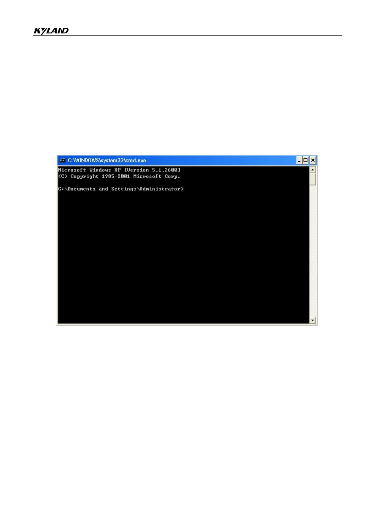
Device Basic Configuration
clients at the same time.
State
Options: Plain text/Encrypted text
Default: Plain text
Function: Select the password display mode.
Click [Start] → [Run] in the Windows OS. The Run dialog box is displayed. Input "cmd"
and press Enter. The following page is displayed.
Figure 90 CLI
The file transmission path can be changed. Log in to the FTP server, as shown in Figure
91.
83

Device Basic Configuration
Figure 91 FTP Server Connection
Use the configured user name "admin" and password "123" to log in to the FTP server, as
shown in Figure 92.
Figure 92 Logging in to the FTP Server
Use the "get" command to download the file to the designated path on client, as shown in
Figure 93. Input the "get" command and press Enter. Input the name of file on switch to be
84

Device Basic Configuration
downloaded in Remote file and the file name saved in client in Local file.
Figure 93 Downloading File from Switch to Client
Use the "put" command to upload the file in the designated path in the client to the server,
as shown in Figure 94. Run the "put" command and press Enter. Input the file name in
switch in Remote file and the name of file in the client to be uploaded in Local File.
Figure 94 Uploading File from Client to Switch
85

Device Basic Configuration
5.14 MAC Address Configuration
5.14.1 Introduction
When forwarding a packet, the switch searches for the forwarding port in the MAC address
table based on the destination MAC address of the packet.
A MAC address can be either static or dynamic.
A static MAC address is configured by a user. It has the highest priority (not overridden by
dynamic MAC addresses) and is permanently valid.
Dynamic MAC addresses are learned by the switch in data forwarding. They are valid only
for a certain period. The switch periodically updates its MAC address table. When receiving
a data frame to be forwarded, the switch learns the source MAC address of the frame,
establishes a mapping with the receiving port, and queries the forwarding port in the MAC
address table based on the destination MAC address of the frame. If a match is found, the
switch forwards the data frame from the corresponding port. If no match is found, the switch
broadcasts the frame in its broadcast domain.
Aging time starts from when a dynamic MAC address is added to the MAC address table. If
no port receives a frame with the MAC address within one to two times the aging time, the
switch deletes the entry of the MAC address from the dynamic forwarding address table.
Static MAC addresses do not involve the concept of aging time.
The switch supports a maximum of 1024 static unicast entries.
5.14.2 Web Configuration
1. Configure MAC binding
Click [Device Basic Configuration] → [MAC address table configuration] → [MAC bind
Configuration] to enter MAC binding configuration page, as shown in Figure 95.
86

Device Basic Configuration
Figure 95 MAC Bind Configuration
MAC bind state
Option: Enable/Disable
Default: Disable
Function: Enable or disable MAC binding function. When enable is selected, for a packet
whose source MAC address and VLAN ID are consistent with the MAC address and VLAN
ID of a static unicast MAC address entry, the switch checks whether the inlet port is
consistent with the port of this static unicast MAC address entry. If yes, the switch receives
and forwards the packet. If no, the switch discards the packet. When disable is selected, the
preceding check is not performed.
2. Add a static unicast MAC address.
Click [Device Basic Configuration] → [MAC address configuration] → [Unicast address
configuration] to enter unicast MAC address configuration page, as shown in Figure 96.
Figure 96 Adding a Static FDB Entry
MAC address
Format: HH-HH-HH-HH-HH-HH (H is a hexadecimal number)
Function: Configure the unicast MAC address. The lowest bit in the first byte is 0.
VLAN ID
Options: all created VLAN IDs
Default: VLAN1
Configuration type
Options: static/blackhole
Default: static
87

Device Basic Configuration
Function: Select the type of the MAC address entry.
Description: Static means establishing mapping between the designated MAC address and
port number or VLAN ID.
Blackhole is to drop the packet whose source MAC address or destination MAC address is
the designated MAC address.
Port list
Options: all switch ports
Function: Select ports to forward the packets with this destination MAC address. The
selected ports must be in the specified VLAN.
3. Delete a unicast address.
Click [Device Basic Configuration] → [MAC address configuration] → [Delete unicast
address] to enter the configuration page, as shown in Figure 97.
Figure 97 Deleting a Unicast MAC Address
Select the criterion for deleting the unicast address. If multiple criteria are selected, their
relationship is logical "And".
4. Configure MAC address aging time.
Click [Device Basic Configuration] → [MAC address configuration] → [MAC address aging
time setting] to enter the aging time configuration page, as shown in Figure 98.
88

Device Basic Configuration
Figure 98 MAC Address Aging Time Configuration
Aging time
Range: 10~100000s
Default: 300s
Function: Set the aging time for the dynamic MAC address entry.
Description: When aging time is set to 0, aging is prohibited. In this case, the address
dynamically learned does not age with time.
5. Query unicast MAC addresses.
Click [Device Basic Configuration] → [MAC address configuration] → [MAC address query]
to enter the unicast MAC address query page, as shown in Figure 99.
Figure 99 Unicast MAC Address Query
Select the criterion for unicast MAC address query. If multiple criteria are selected, their
relationship is logical "And". For example: If you query the unicast address of port Ethernet
1/1, the following page is displayed.
Figure 100 Unicast MAC Address List
6. View unicast address entries.
Click [Device Basic Configuration] → [MAC address configuration] → [Show mac-address
table] to enter the unicast MAC address query page. All dynamic and static entries are
displayed, as shown in Figure 101.
89

Device Basic Configuration
Figure 101 Unicast Address Query
5.15 Basic Configuration Maintenance and Debugging Information
When configuring the switch, you may need to check the correctness of various
configurations to ensure normal running; or when certain anomalies occur, you may need to
locate the fault. In these cases, you can perform the following operations to view system
configurations and running status.
1. Ping operation.
Click [Device Basic Configuration] → [Basic configuration debug] → [Ping and Traceroute] to
enter ping operation page, as shown in Figure 102.
Figure 102 Ping Operation
IP address
Format: A.B.C.D
Description: Input the IP address of the remote device.
Hostname
Range: 1~30 characters
90
 Loading...