


103
Multi-Speed
Combination
Brake
Lathe
Instruction Manual and Parts List
Kwik-Way Products Inc.
Copyright © 2005, All Rights Reserved
Equipment, specifications, options and accessories subject to change without notice Part #


103 Multi-Speed Brake Lathe
521 WARRANTY
Brake Lathes • Tire Changers • Wheel Balancers
KWIK-WAY
provides a limited 521 Warranty on products when purchased in a new and unused condition to be free from
defective material or workmanship from date of purchase as per the following:
Product BENCH MODEL ON-CAR-LATHES PASSENGER CAR WHEEL BALANCERS TRUCK LATHES
Category LATHES TIRE CHANGERS AND
TIRE CHANGERS
5 Years
Spindle, spindle bearing Cast iron components, Transmission Frame, welding N/A
and housing excluding guide rods construction
2 Years
All other mechanical All other mechanical Pedal controls Shaft N/A
parts parts
1 Year
Electrical motors and Electric motors and Parts, electrics and Parts, electrics and Parts, electrics and
labor labor labor labor labor
This warranty does not apply to a product that has been purchased in used condition, that has failed due to improper
installation, repairs, service or that has sustained damage caused by accident, improper use or shipment.
Kwik-Way
will repair and/or replace, free of charge (FOB factory) all such defective parts, only when returned to factory with
shipping charges prepaid. This warranty does not cover parts and supplies consumed in normal operation of the machine.
Kwik-Way
disclaims all other warranties, expressed or implied, as to the quality of any goods, including implied warranties of
MERCHANTABILITY and FITNESS FOR PARTICULAR PURPOSES. UNDER NO CIRCUMSTANCES WHATSOEVER, SHALL KWIKWAY BE LIABLE FOR ANY INCIDENTAL OR CONSEQUENTIAL DAMAGES, WHETHER BASED ON LOST GOODWILL, LOST
RESALE PROFITS, WORK STOPPAGE, IMPAIRMENT OF OTHER GOODS OR ARISING OUT OF BREACH OF ANY EXPRESS OR
IMPLIED WARRANTY, BREACH OF CONTRACT, NEGLIGENCE OR OTHERWISE, EXCEPT ONLY IN THE CASE OF PERSONAL
INJURY WHERE APPLICABLE LAW REQUIRES SUCH LIABILITY. This limited warranty gives you specific legal rights and you
may also have other rights which vary from state to state. This document contains the complete text of this warranty and may
not be modified either orally or in writing.
Because of
KWIK-WAY
’s constant program of product improvement, specifications are subject to change without notice.
Office Hours: 7:30 to 5:00 Central Time
Kwik-Way Products Inc.
500 57th Street
Marion, Iowa 52302
Toll Free
1-800-553-5953
Fax 319-377-9101
www.kwik-way.com
service@kwik-way.com


103 Multi-Speed Brake Lathe
Replac ement Parts & Supplies - 800-553-5953 1
Receiving Shipment
Upon taking delivery of your machine, carefully inspect the assembly before removing the
crating and packing materials.
If evidence of damage exists, contact the shipper and Kwik-Way Products Inc.immediately.
Although Kwik-Way Products Inc.is not responsible for damage incurred during transit, you
will be provided assistance in preparation and filing of any necessary claims.
CAREFULLY READ THIS MANUAL BEFORE ATTEMPTING TO SET-UP OR OPERATE
THIS MACHINE.
Important Note:
Always have your serial number ready when communicating with Kwik-Way Products Inc
.
regarding parts or service.
Keep this manual in a safe place.
Kwik-Way Products Inc.
500 57th Street
Marion, Iowa 52302
319-377-9421
Fax 319-377-9101
Toll Free
1-800-553-5953
www.kwik-way.com
Date
Received ________________________________________
Serial Number ____________________________________

1
1
1
1
S
P
8
8
8
A
8
0
1
1
8
8
1
1
1
8
8
8
8
8
8
B
1
1
M
1
1
1
8
0
0
0
8
8
O
A
8
8
8
8
8
C
8
8
1
1
1
8
D
8
8

103 Multi-Speed Brake Lathe
Replacement Parts & Supplies - 80 0-553-5953 3
103 Multi-Speed Combination Lathe
103-8680-30 115 V, 60 Hz, 1 Ph
103-8680-31 230 V, 60 Hz, 1 Ph
103-8680-32 230 V, 50 Hz, 1 Ph
S TANDARD EQUI PMENT IN CLUDED
Part No. Description
8 0 4 - 8 6 9 1 - 6 8 Twin Cu tter with Damp ener A s s y
8 0 4 - 8 6 9 1 - 7 5 Tool Bar & Bit Holder Assy f or Drums
8 0 4 - 8 6 9 1 - 7 6 Carbide Bit Package
4 Roto r Bits (3 Cutting Edges) 2 Drum Bits (2 Cutting Edg es )
Arbor Components
8 0 4 - 8 6 9 1 - 7 8 1" Arbor w/ Nut 12.00" (304.80 mm) Long
0 0 0 - 1 8 0 6 - 7 0 S p r i n g
1 0 9 - 1 0 3 2 - 0 9 S p a c e r, 1 " (2 5. 4 mm) (2 Included)
1 0 9 - 1 0 3 3 - 0 6 S p a c e r, 2 " (5 0. 8 mm)
8 0 4 - 8 6 6 3 - 9 0 Draw Bar
8 0 4 - 8 6 6 5 - 0 0 Tapere d Cone Set for 1" A r b o r
1 0 1 - 0 2 4 3 - 0 0 Cone, 1.70 x 2.3 5 (43. 18 x 59.69 mm)
1 0 1 - 0 2 3 6 - 0 5 Cone, 1.98 x 3.4 4 (50. 29 x 87.38 mm)
1 0 1 - 0 2 3 7 - 0 2 Cone, 3.35 x 4.0 0 (85. 09 x 101.60 m m)
8 0 4 - 8 6 5 8 - 2 2 Double Ended C on e Se t fo r 1" A r b o r
8 0 4 - 8 6 5 8 - 2 3 Cone, 1.32 x 1.6 7 (33. 53 x 42.42 mm)
8 0 4 - 8 6 5 8 - 2 4 Cone, 1.36 x 1.7 1 (34. 54 x 43.43 mm)
8 0 4 - 8 6 5 8 - 2 5 Cone, 1.71 x 2.0 7 (43. 43 x 52.58 mm)
8 0 4 - 8 6 5 8 - 2 6 Cone, 2.07 x 2.4 4 (52. 58 x 61.98 mm)
8 0 4 - 8 6 5 8 - 2 7 Cone, 2.44 x 2.8 9 (61. 98 x 73.40 mm)
Bell Clamps
1 0 9 - 1 0 11 - 0 9 4.25" O.D. (107.95 mm) (2 Inclu ded)
1 0 1 - 0 2 3 5 - 4 0 5.75" O.D. ( 146.05 m m) (2 In cl uded)
M i s c e l l a n e o u s
1 0 8 - 1 0 6 1 - 0 0 Vented Silencer-Ro to r
1 0 9 - 1 0 3 2 - 0 9 S p a c e r, 1 x 1.5 x 1. 5
1 0 1 - 0 2 3 0 - 1 0 Automotiv e Drum Silencer
8 0 4 - 8 6 6 5 - 4 1 Solid Rotor Silencer Magnetic Band
0 0 0 - 0 6 0 0 - 7 0 Hex Key, .187" (4.7 5 mm )
0 0 0 - 0 6 0 0 - 5 4 Hex Key, .125" (3.1 8 mm )
0 0 0 - 0 6 0 0 - 2 0 Hex Key, .312" (7.9 3 mm )
8 0 4 - 8 6 6 4 - 4 3 Wrench, Draw Bolt
8 0 4 - 7 8 0 3 - 3 5 Wrench, Arbo r Nut
O P T I O N A L A C C E S S O R I E S
A d a p t e r s
8 0 4 - 8 6 9 1 - 8 5 11/16” Arbor with Nut, Cone & Wa s h e r, B or e .875-11.25” (22.23-3 1. 75 mm),7.375 ” (198.3 3m m)long
8 0 4 - 8 6 9 1 - 7 8 1” Arbor with Nut & Wa s h e r, 9.75” (246.65mm) long
8 0 4 - 8 6 9 1 - 8 8 Extended 1” Arbor with Nut & Was he r (2” longer) 12” (304.8 ) long
8 0 4 - 8 6 9 1 - 9 1 2” Arbor with Nut & Wa s h e r, 15.75 ” (400.0 5mm) long)
8 0 4 - 8 6 9 1 - 9 2 Extended 2” Arbor with Nut & Wa s h e r, 19.88” (504.95mm) l ong
Centering Cones
8 0 4 - 8 6 6 4 - 6 5 Cpme Set fpr 1” A r b o r
8 0 4 - 8 6 6 4 - 4 5 Cone, 1.15x1.80 (29.21x45 .7 2 mm )
1 0 1 - 0 2 4 3 - 0 0 Cone, 1.70 x 2.3 5 (43. 18 x 59.69 mm)
1 0 1 - 0 2 3 6 - 0 5 Cone, 1.98 x 3.4 4 (50. 29 x 87.38 mm)
1 0 1 - 0 2 3 6 - 0 2 Cone, 3.35 x 4.0 0 (85. 09 x 101.60 m m)
8 0 4 - 8 6 6 4 - 5 0 Cone, 3.90x4.55 (99.06x115.50 mm)
Double Ended Con es for la rger hubbed drums & r o t o r s
8 0 4 - 8 6 6 5 - 1 5 Cone, 2.82x3.18 (73.41x82 .8 0 mm )
8 0 4 - 8 6 6 5 - 1 6 Cone, 3.20x3.56 (82.80x91 .9 5 mm )
STANDARD & OPTIONAL EQUIPMENT

4 Replac em ent Parts & Supplies - 800-553-5953
103 Multi-Speed Brake Lathe
Part # Description
804-8691-95 Hubless Adapter Set, Small Size for 1" Arbor, Bore Range 1.87"-3.00" (47.50 76.20 mm)
804-8691-93 Rotor Locator-RH
804-8659-61 Cone, 1.88x3.13 (47.63x79.38 mm)
804-8659-62 Spacer
804-8691-94 Locator Nut-RH
804-1251-10 Wrench, Spanner
804-8691-98 Hubless Adapter Set, Std Size for 1" Arbor, Bore Range 2.03"-3.93" (51.56-99.82 mm)
804-8691-96 Rotor Locator-RH
804-4151-85 Cone, 2.12x4.00 (53.85x101.60 mm)
804-4151-86 Spacer
804-8691-97 Locator Nut-RH
804-1251-10 Wrench, Spanner
804-8692-01 Hubless Adapter Set, Large Size for 1" Arbor, Bore Range 4.00"-5.75" (101.60- 146.05 mm)
804-8691-99 Rotor Locator-RH
804-4161-85 Cone, 3.68x5.93 (93.47x150.62 mm)
804-4161-86 Spacer
804-8692-00 Locator Nut-RH
804-1168-49 Wrench, Spanner
804-8692-02 Hubless/Composite Rotor Adapter Kit of 1” Arbor
804-8691-98 Hubless Adapter set, Std Size
804-8631-85 Backing Plate for 804-8631-87, 804-8657-12, 804-8656-98
804-8631-87 Adapter Plate, GM "W-Body"/Lincoln
804-8631-88 Backing Plate, Chevy 1500 (for 804-8631-89)
804-8631-89 Adapter Plate, Chevy 1500
Composite Rotor Backing Plates for 804-8691-98
804-8656-98 Adapter Plate, Jeep Cherokee
804-8657-12 Adapter Plate , Eagle Premier
804-8692-05 Hubless Adapter Set, Large Size for 2" Arbor, Bore Range 4.00-5.75" (101.60-146.05 mm)
804-8692-04 Rotor Locator-RH
804-4161-85 Cone, 3.68x5.93 (93.47x150.62 mm)
804-4161-86 Spacer
804-8692-00 Locator Nut-RH
804-1168-49 Wrench, Spanner
804-8664-66 Medium Truck Set for 2" Arbor, Bore Range 2.15"-6.10" (54.61-154.94mm) for HublessDrums/Discs
804-8664-53 Cone, 2.15x2.80 (54.61x71.12 mm)
804-8664-54 Cone, 2.70x3.35 (68.58x85.09 mm)
804-8664-55 Cone, 3.25x3.90 (82.55x99.06 mm)
804-8664-56 Cone, 3.80x4.45 (96.52x113.03 mm)
804-8664-57 Cone, 4.35x5.00 (110.49x127.00 mm)
804-8664-58 Cone, 4.90x5.55 (124.46x140.97 mm)
804-8664-59 Cone, 5.45x6.10 (138.43x154.94 mm)
101-0638-01 Spring
804-8662-02 Clamp Bell, 7.75" (2 Included)
804-7803-05 Spacer, 2" (50.80 mm)
804-7803-01 Spacer, 3" (76.20 mm)
804-8664-67 Heavy Truck Set for 2" Arbor, Bore Range 5.45"-8.30" (138.40-210.80 mm) for hubless
Drums/Discs
804-8664-59 Cone, 5.45x6.10 (138.43x154.94 mm)
804-8664-60 Cone, 6.00x6.65 (152.4x168.90 mm)
804-8664-61 Cone, 6.55x7.20 (166.30x182.80 mm)
804-8664-62 Cone, 7.10x7.75 (180.30x196.80 mm)
804-8664-63 Cone, 7.65x8.30 (194.30x210.80 mm)
101-0638-01 Spring
804-3000-84 Clamp Bell, 9.25" (2 Included)
804-7803-05 Spacer, 2" (50.80 mm)
804-7803-01 Spacer, 3" (76.20 mm)

103 Multi-Speed Brake Lathe
Replac ement Parts & Supplies - 800-553-5953 5
Part # Description
804-8665-47 Basic Bench, Heavy Gauge 22"Wx38"x26"L, (558.80x965.20 x 660.0mm) w/Lower Tool Board,
Chip Tray, and Adapter Hooks
804-8410-33 341 Deluxe Bench, Heavy Gauge 22"Wx38"Lx71"H (558.80x965.20x1803.40mm)
w/ 2 Tool Boards, Chip Tray, Adapter Hooks, and Arbor Rack
804-8674-93 Bench Conversion Assembly
Converts Basic Bench to Deluxe Bench
Flywheel Accessories
804-8692-10 Small Hole Flywheel Adapter Kit
804-8692-09 Small Hole Flywheel Adapter
804-8692-08 Arbor
804-8692-07 Tapered Bolt
804-8692-11 Tool Holder
804-8682-05 Insert (3)
804-8682-06 Slotted Screw (3)
804-8682-69 1.25" ID Lock Collar
804-8690-92 1.00" ID Pillow Block Bearing
Miscellaneous
804-8665-64 Rotor Bits - Pkg/10, (3 Cutting Edges) + Rake with Holes
804-8665-61 Rotor Bits - Pkg/10, (3 cutting edges) 1/64” (.4mm) Radius
804-8692-06 Drum Bits - Pkg/10 (2 Cutting Edges)
804-8665-42 Truck Drum Silencer 2.75" (69.85 mm) Wide
804-8665-43 Brake Drum Wear Limit Gage
804-8665-44 Rotor Micrometer Range .30"-1.30" (7.62-33.02mm)
804-2049-60 Drum Grinder, 115v,50/60hz,1ph
804-8668-08 Disc Rotor Swirl Finisher
804-8668-09 Replacement Pads 25 Count, 80 Grit
804-8668-10 Replacement Pads 25 Count, 120 Grit
804-2049-69 T-Bar Holder
804-8665-45 Safety Shield
804-8685-12 Extra Large Bell & Cone Set for 2"
Arbor, Bore Range 8.06"-9.95" (204.8 -252.8 mm) for Hubless Drums/Discs
804-8685-10 Cone, 8.06x9.95"
804-8685-09 Clamp Bell, 12" (2 Included)
804-8685-11 Spring, Heavy Duty
804-8692-14 Outboard Support Kit
804-8691-92 Extended 2" Arbor w/ Nut & Washer 19.88" (504.95mm) Long
804-8682-66 Outboard Support Base Weldment
804-8682-67 Bearing Support Weldment
804-8682-69 1.25” ID Lock Collar
804-8690-92 1.00” ID Pillow Block Bearing

6 Replac em ent Parts & Supplies - 800-553-5953
103 Multi-Speed Brake Lathe
SAFETY FIRST
This manual has been prepared for the owner and those responsible for the maintenance of this machine.
It’s purpose aside from proper maintenance and operations is to promote safety through the use of
accepted practice. READ THE SAFETY AND OPERATING INSTRUCTIONS THOROUGHLY BEFORE
OPERATING THE MACHINE.
In order to obtain maximum life and efficiency from your machine; follow all the instructions in the
operating manuals carefully.
The specifications put forth in this manual were in effect at the time of publication. However, owing to
Kwik-Way Products’
policy of continuous improvement, changes to these specifications may be made at
any time without obligation.
SAFETY INSTRUCTIONS

103 Multi-Speed Brake Lathe
Replac ement Parts & Supplies - 800-553-5953 7
1. Read, understand and follow the safety and operating instructions found in this manual. Know
the limitations and hazards associated with operating the machine.
2. Eye Safety: Wear an approved safety face shield, goggles or safety glasses to protect eyes
when operating the machine.
3. Grounding the Machine: Machines equipped with three prong grounding plugs are so equipped
for your protection against shock hazards and should be plugged directly into a properly
grounded three-prong receptacle in accordance with national electrical codes and local codes
and ordinances. A grounding adapter may be used. If one is used, the green lead should be
securely connected to a suitable electrical ground such as a ground wire system. Do not cut
off the grounding prong or use an adapter with the grounding prong removed.
4. Work Area: Keep the floor around the machine clean and free of tools, tooling, stock scrap and
other foreign material and oil, grease or coolant to minimize the danger of tripping or slipping.
Kwik-Way recommends the use of anti-skid floor strips on the floor area where the operator
normally stands and that each machine's work area be marked off. Make certain the work area
is well lighted and ventilated. Provide for adequate workspace around the machine.
5. Guards: Keep all machine guards in place at all times when machine is in use.
6. Do Not Overreach: Maintain a balanced stance and keep your body under control at all times.
7. Hand Safety: NEVER wear gloves while operating this machine.
8. Machine Capacity: Do not attempt to use the machine beyond its stated capacity or operations.
This type use will reduce the productive life of the machine and could cause the breakage of
parts, which could result in personal injury.
9. Avoid Accidental Starting: Make certain the main switch is in the OFF position before
connecting power to the machine.
10. Careless Acts: Give the work you are doing your undivided attention. Looking around, carrying
on a conversation and horseplay are careless acts that can result in serious injury.
11. Job Completion: If the operation is complete, the machine should be emptied and the work
area cleaned.
12. Disconnect All Power and Air to Machine before performing any service or maintenance.
13. Replacement Parts: Use only Kwik-Way replacement parts and accessories; otherwise,
warranty will be null and void.
14. Misuse: Do not use the machine for other than its intended use. If used for other purposes,
Kwik-Way Products Inc.
disclaims any real or implied warranty and holds itself harmless for
any injury or loss that may result from such use.

8 Replac em ent Parts & Supplies - 800-553-5953
103 Multi-Speed Brake Lathe
E L E C T R I C A L R E Q U I R E M E N T S
1. The 103 is available in three electrical configurations: 115V, 60 Hz, 1 Ph; 230V, 60 Hz, 1 Ph; and electricals of 230V, 50 Hz, 1 Ph.
IMPORTANT: Before connecting the lathe to a power source (receptacle, outlet, etc.), be sure the power
switch is in the “Off” position and the voltage source available is the same as that specified on the Serial
plate of the lathe. A power source with voltage greater than that specified for the machine can result in
SERIOUS INJURY to the user -- as well as damage to the lathe.
2. The machine is equipped with a standard 3 conductor cord with a 3 prong grounding type plug that fits
into the standard grounding type receptacle. Never do anything to defeat the grounding terminal on this
machine. Replace only with the same style plug. If an extension cord is required, use a heavy duty type
with a 3 prong grounding type plug. An under-sized cord will cause a drop in line voltage, resulting in
loss of power and over-heating.
NOTE: The 115V machines include a standard 3 prong grounded plug.
The 230V machines will not have a plug. Only the power cord will be
provided -- contact an electrical professional for the proper plug.
3. One of the following fused service lines is required for this machine —
check the serial no. plate located at rear of your machine:
115V, 60 Hz, 1 Ph: 20 amp, 12 gage wire
230V, 60 Hz, 1 Ph: 15 amp, 14 gage wire
230V, 50 Hz, 1 Ph: 15 amp, 14 gage wire
4. The 103 has two separate fuses located under the electrical control box.
Access these fuses from the rear of the machine (Figure 1). The 1/2 Amp fuse protects the 2 - DC drive
feed motors. The 1 Amp fuse protects the electrical control box circuitry.
5. The 1 HP motor is protected by a thermal overload limit switch that must be manually reset if an overload
occurs.
115V
1/2 Amp
Fuse
1 Amp
Fuse
Figure 1

103 Multi-Speed Brake Lathe
Replac ement Parts & Supplies - 800-553-5953 9
MOUNTING ON BENCH
1. If the optional 103 Deluxe Bench Part # 804-8665-
29 or Basic Bench Part #804-8665-47 was
purchased, assemble per instructions included
with bench. Otherwise, select a bench that is
about 30 inches tall and capable of supporting an
operating brake lathe with it’s dynamic forces
assume 425 lbs. static weight.
2. Remove the 4 bolts holding the lathe to the
shipping pallet. Lift the lathe using the eye bolt
provided (Figure 2). Do not lift the machine by
the spindle, belt pulley cover, or either of the disc
or drum cross slides. This could damage the lathe
and would void the warranty on the unit.
3. Place the four rubber pads on the bench and
mount lathe to the bench using the four bolts
provided thru the four feet of the lathe. Secure
with washers and nuts from the bottom side of the
bench.
4. Remove eye bolt and replace with the 1/2-13 setscrew provided. Turn until flush with surface.
5. Install handwheel handles and motor bracket
handle.
POSITION MOTOR DRIVE BELT AND
TENSION PROPERLY BEFORE USE
1. The 103 is shipped with all belts pro p e r l y
tensioned with the exception of the motor drive 4
Groove Poly-V belt. The 103 was shipped with
the motor drive belt off the motor drive pulley so
the belt would not be stretched during shipment
of your machine. Refer to belt tensioning
instructions, page 7, Figures 7 thru Figure 10 to
assure proper tension of the motor drive belt
before operating machine.
PREPARING FOR USE
1. Remove the rust-preventative on the machine
ways with an approved commercial solvent. The
dove tail ways should be kept dry and should
always be free from grease, oils, etc.
2. Unwrap all adapters and accessories. Clean with
an approved commercial solvent. Check for any
damage during shipment such as burrs, nicks,
scratches, etc. Remove minor niches and
scratches with a fine file or sharpening stone.
Apply a protective coat of very light oil to prevent
parts from rusting.
3. Hang adapters on a tool board to protect from
damage while not in use.
4. Unpack work light. Mount on top of spindle
housing (Figure 4). Plug into outlet provided on
rear of electrical control box.
5. Plug machine into appropriate electrical outlet.
Refer to the Electrical Requirement Section if
t h e r e is any doubt re g a r ding the corre c t
procedure. To turn on the lathe, pull the POWER
switch (Figure 4). The spindle should turn
counterclockwise when viewing the taper end.
INSTALLATION
Figure 4
Figure 2
Eye
Bolt
Work Light Mount

1 0 Replac em ent Parts & Supplies - 800-553-5953
103 Multi-Speed Brake Lathe
7
8
9
10
11
14
15
13
1
12
2
3
4 5
16
22
24
20
21
17
23
19
COMPONENT & CONTROL
IDENTIFICATION
6
16
17
18
Figure 3
1. Disc Slide Handwheel (cross feed)
2. Spindle
3. Main Power Switch & Emergency Stop
4. Function Switch — selects the drum
or disc slides
5. Feed Rate Control for both drum and disc
6. Work Light Mount
7. Drum Slide Gib Adjustment Screws and Lock
(behind slide)
8. Limit Switches — one for the drum slide and
one for the disc slide to prevent overtravel
during power feed operation.
9. Way Cover
10. Drum Slide Feed Screw Lock
11. Drum Slide Handwheel (traverse feed)
12. Variable Speed DC Gear motors (behind cover)
13. Disc Slide Gib Adjustment Screws & Lock
14 Disc Slide Feed Screw Lock (behind
handwheel)
15. Disc Slide Handwheel
16. Motor Bracket Handle
17. Motor Bracket Clamp
18. Belt Access Door Latch
19. Outlet for Work Light
20. 3/8 Amp Fuse
21. 1 Amp Fuse
22. Motor
23. Power Cord
24. Reset Button

103 Multi-Speed Brake Lathe
Replac ement Parts & Supplies - 800-553-5953 1 1
Specifications
Motor 1 HP
Spindle speeds .......................................................................................................................60, 120, 170 RPM
Feed speeds, infinitely variable 0 to —
Per min. ......................................................................................................................................2.10" (53 mm)
Rotor size
Maximum diameter ....................................................................................................................24" (609 mm)
Maximum thickness....................................................................................................................2.5" (63 mm)
Flywheel size
Maximum diameter ....................................................................................................................24" (609 mm)
Maximum thickness................................................................................................................7.25" (184 mm)
Drum size
Minimum diameter .......................................................................................................................6" (152 mm)
Maximum diameter.....................................................................................................................28" (711 mm)
Maximum depth............................................................................................................................9" (229 mm)
Machine Net weight .................................................................................................................415 lbs. (188 kg)
Shipping weight....................................................................................................................555 lbs. (252 kg)
Lathe Bench (optional)
Size22" x 38" x 71"
(559 x 965 x 1803 mm)
Weight .........................................................................................................................................140 lbs. (64 kg)
Kwik-Way is committed to product innovation and improvement and therefore reserves the right to change product
specifications without notice

1 2 Replac em ent Parts & Supplies - 800-553-5953
103 Multi-Speed Brake Lathe
.INSTALLATION OF ARBOR
1. The 1" diameter arbor is included with the 103 as standard equipment and is capable of handling work
pieces up to 150 lbs. If the work piece is heavier the 150 lbs, it will be necessary to use the optional 2" Heavy
Duty Arbor.
2. Insert arbor into spindle taper (Figure 5).
IMPORTANT: Both the arbor and the spindle taper must be clean, otherwise arbor will have run out and the
taper may be damaged. Align pin in arbor with slot in main spindle. Screw in draw bar (Figure 6) and
tighten (Figure 7). DO NOT tighten excessively. Driver pin will prevent arbor from slipping. To remove
arbor easily (arbor has a non-locking taper) loosen draw bar slightly and tap lightly on the end of the draw
bar. Hold the arbor with one hand to prevent arbor from falling while unscrewing draw bar.
3. Don’t hammer upward or downward on draw bar as damage may occur to both arbor and draw bar.
Figure 5 Figure 6
Figure 7

103 Multi-Speed Brake Lathe
Replac ement Parts & Supplies - 800-553-5953 1 3
SELECTING THE SPINDLE SPEED
MAKE CERTAIN POWER SWITCH IS IN THE OFF POSITION before changing the spindle speed.
1. The 3 spindle speeds on the 103 are 60, 120, & 170 RPM’s. To select the desired speed, lift and turn the
latch handle to open the belt access door (Figure 8). Loosen the belt tensioning lock by pushing down on
the lever (Figure 9). Move the motor bracket handle forward to allow the belt to be moved to a different
pulley groove (Figure 10).
2. The outer pulley groove (high speed) is for the smaller rotors and drums,
and the inner pulley groove (low speed) is for the very large rotors and
drums. KW Products (Kwik-Way) recommends that the operator start out
in the middle pulley groove and then adjust the desired spindle speed
upward or downward from that point. Belt must be aligned in the same
upper and lower pulley groove position.
3. Reposition the motor bracket handle to the rear slightly (Figure 11). This
will apply proper tension to the belt. Re-tighten the motor bracket
clamp by moving the lever upward. DO NOT over tighten belt.
SELECTING THE FEED DIRECTION
1. The 103 function switch selects the proper feed direction (Figure 12). With
the switch setting on DISC, the machine will feed across the face of the
rotors. When the switch is set on DRUM the slide will feed left to right for
machining drums.
2. Whenever the machining operation has been completed, always move the
switch into the neutral “OFF” position.
Figure 8
Figure 10Figure 9
Figure 11
Figure 12

1 4 Replac em ent Parts & Supplies - 800-553-5953
103 Multi-Speed Brake Lathe
SELECTING THE FEED RAT E
1. The 103 features an infinitely variable feed on both the disc slide and the drum
slide. This will allow the operator to totally control surface finish and
machining time for drums and discs. Refer to chart below for the spindle
speed/feed rate ratio to determine the optimum feed rate.
2. The feed rate knob (Figure 13) can be adjusted from a setting of “0” (no feed)
to “10” (fast feed), or any position in between. The lower the number, the
slower the feed, and the smoother the finish -- the higher the number, the
faster the feed, and the coarser the finish.
SPINDLE SPEED/FEED CHART
APPROXIMATE INCHES/REVOLUTION AT VARIOUS RPM AND FEED DIAL SETTINGS
ENGAGING THE FEED
1. Both the disc slide and the drum slide can be manually operated in either
direction by turning the handwheel. The disc slide feed lock knob
(Figure 14) and the drum slide feed lock knob (Figure 15) however,
must be disengaged in order for the slides to be manually operated.
2. To engage the power feed on the disc or drum slide requires the operator to
engage the disc slide feed lock knob or the drum slide feed lock knob. The
power feed will not operate properly without these knobs engaged.
3. When the machining operation has been completed shut lathe off and
disengage the knob to prepare for the next job.
Figure 13
.027
.024
.020
.016
.012
.008
.004
0
60
5 10
Feed Dial Settings
120
170
Figure 14
Figure 15

103 Multi-Speed Brake Lathe
Replac ement Parts & Supplies - 800-553-5953 1 5
DEPTH OF CUT DIAL
1. The drum depth-of-cut micrometer is located on the
cross slide handwheel (Figure 16). This handwheel is
used for moving the tool bit into the brake drum. The
dial has a scale to indicate amount of material to be
removed from the drum diameter.
2. The divisions on the handwheel dial are 0.002" and the
scale is direct reading. For example, if the scale is
i n c r eased .016" (8 divisions) there will be .008”
removed from each side of the drum increasing the
diameter by .016". No calculations have to be made by
the operator.
DRUM BAR TOOLING ASSEMBLY
The 103 Drum Bar, Part Number 804-8671-10, is machined at both ends. The end of the bar
with the machined slot and the two set screws is used for larger drums and flywheels. The
end of the bar that is reduced in width is for machining small drums. Two drums bits are
included with the 103, therefore is is recommended that a bit is installed in each end.
1. Insert the drum bit in the Tool Bit Holder, Part #804-3021-71 (Figure 17).
2. Assemble the bit clamp and set screw (Figure 18).
Tighten securely.
3. Place the Tool Bit Holder Assembly in the end slot of the drum bar and tighten the two
set screws (Figure 19).
4. Insert the other drum bit in the slot provided in the narrow end of the drum bar. Make
certain the bit is inserted as far as possible (Figure 20).
5. Tighten set screw
(Figure 21).
P R E PARING DRUMS FOR MACHINING
1. First, measure the diameter of the drum with a micrometer to determine that the drum will be within
maximum oversize limits after reconditioning. The drum should also be in good general condition. THE
MAXIMUM REBORING LIMIT DIMENSION IS
CAST INTO THE DRUM BY THE MANUFACTURER. NEVER
EXCEED THIS LIMIT OR THE DRUM COULD FAIL IN USE RESULTING IN BRAKE FAILURE.
IMPORTANT: To prevent galling, scratching the newly machined surface clean the drum before mounting.
Use a wire brush or a rotary wire brush in a drill to thoroughly clean all mounting surfaces. Make certain
all rust is removed from both inside and outside bolt patterns and that the inside diameter of the center bore
is absolutely clean and free from any burrs.
Figure 16
Figure 17
Figure 18
Figure 19
Figure 20 Figure 21

1 6 Replac em ent Parts & Supplies - 800-553-5953
103 Multi-Speed Brake Lathe
1. HUBLESS DRUMS (Fig. 22) are mounted using 2 bell clamps of the same size, a tapered cone, a spring,
and spacers. Make certain the mounting pads of the bell clamps are clean and free of nicks, burrs, etc.
Mount the drum as shown:
2. DRUMS WITH HUBS (Fig. 23) are mounted using 2 double ended cones.
3. Optional Hubless Adapter Set (Fig. 24)
MACHINING DRUMS
1. After the drum is mounted on the arbor, wrap and secure the drum silencer band
tightly around the drum (Figure 25). Cover as much of the outside of the drum as
possible.
2. Assemble and mount the drum tool bar on the slide as illustrated (Figure 26 & 27).
3. Position the tool bar by loosening the tool bar clamp nut
(Figure 28) and sliding the tool bar inward toward the
drum until the tool bit is close to the surface that is going
to be machined. The entire tool bar assembly may also
be swiveled to achieve the best cutting position.
Make certain the set screws and tool bar clamp nut are
tight before machining.
Figure 28
Wear proper eye protection
when operating machine.
Figure 25
Figure 26
Figure 27
Bell Clamp
Tapered Cone
Spring
Bell Clamp
Figure 22
Double
Ended
Cone
Spacer
Double
Ended
Cone
Locator
Nut
Spacer
Spacer
Rotor Locator
Cone
Figure 24
Figure 23
Spacer

103 Multi-Speed Brake Lathe
Replac ement Parts & Supplies - 800-553-5953 1 7
4. On smaller drums position the tool bar and bit at the outer edge of the drum to
insure that the tool bar will not contact the spindle housing during machining.
It may be necessary to use spacers to position the drum further out on the arbor
to allow clearance for the tool bar. On 6" diameter drums the inner clamp bell
and spring should be replaced with spacers to allow room for the cutter bit.
5. Turn the lathe on and advance the tool bit until it just contacts the drum
surface and makes a scratch cut. Back the tool bit off and stop the lathe.
Loosen the arbor nut and rotate the drum one-half turn. Retighten the nut, turn
the lathe on and make a second scratch cut, stop the lathe. If the first and the
second scratch cuts are opposite each other (180° apart) remove the drum from
the arbor. Check the mounting adapters and the arbor for nicks, burrs, or chips.
Clean if necessary. If the first and second scratches are side by side, proceed
in machining the drum.
6. Turn the traverse feed handwheel (Figure 29) until the deepest worn groove of
the drum is aligned with the point of the tool bit. Advance the tool bit into the
bottom of the groove by turning the cross feed handwheel (Figure 30)
counterclockwise. Note handwheel reading then back off (clockwise) 1/2 turn.
Move cutter to inside edge of surface to be machined using the traverse feed
handwheel.
7. Reset the depth of cut by turning the cross feed handwheel to the reading
obtained in “STEP 6” above plus .003". Maximum depth of cut is .015".
Lock the cross feed slide lock (Figure 31). This will keep the slide in a fixed
position for an accurate machining job.
8. Turn on main power to start spindle. Turn drum slide feed screw lock in to
keep feed screw from turning. Set feed rate to “0” and position function switch
to DRUM. Slowly increase feed rate until desired feed is obtained.
9. After cut is complete turn function switch to “Off” and shut off main power.
Examine drum for complete clean-up. If additional cuts are required repeat
steps 7 and 8.
10. If the drum is to be finished in a single pass use a slow feed rate. If a roughing
cut is being made then a faster feed rate may be used for the first cut and a slow
feed rate for the final cut.
Figure 29
Figure 30
Figure 31

1 8 Replac em ent Parts & Supplies - 800-553-5953
103 Multi-Speed Brake Lathe
P R E PARING DISCS ROTORS FOR MACHINING
1. Before machining, each disc rotor should be carefully inspected for scoring, rust, ridges (at the inner and
outer circumference of the rotor) and hard spots. Any excessive wear or deformity should be noted and, if
not within acceptable limits, the rotor should be replaced.
2. Using a micrometer check the thickness of the rotor in at least three points around the circumference about
1" (2.54 cm) in from the outer diameter. If the rotor thickness varies between readings it should be
machined. However, if the thickness is less than the minimum established by the rotor manufacturer, or it
will be after resurfacing, the rotor should be replaced.
THE MINIMUM REFINISHED THICKNESS DIMENSION IS CAST INTO THE ROTOR.
NEVER MACHINE BEYOND THIS LIMIT OR THE
DISC COULD FAIL IN USE RESULTING IN
VEHICLE BRAKE FAILURE.
IMPORTANT: Clean the disc before mounting. Use
a wire brush or a rotary wire brush in a drill to
t h o rough ly clean all mounting surfaces. Make
certain all rust is removed from both inside and
outside bolt patterns and that the inside diameter of
the center bore is absolutely clean and free from any
burrs.
MOUNTING DISC/ROTORS
1. HUBLESS DISCS (Fig. 32) are mounted using 2 bell
clamps of the same size, a tapered cone, a spring,
and spacers. Make certain the mounting pads of the
bell clamps are clean and free of nicks, burrs, etc.
Disc Rotors should be mounted as close to the
spindle as possible.
THE ARBOR NUT SHOULD NOT BE OVER
TIGHTENED.
Tapered Cone
Bell Clamp
Bell Clamp
Spring
Figure 32
Spacer
Double Ended Cone
Double Ended
Cone
2. DISCS WITH HUBS (Fig. 33)
are mounted using 2 double
ended cones.
Figure 33
Cone
Spacer
Locator Nut
Rotor Locator
3. Optional Hubless
Adapter Set (Fig. 34)
Figure 34

103 Multi-Speed Brake Lathe
Replac ement Parts & Supplies - 800-553-5953 1 9
MACHINING DISC/ROTORS
MOUNTING TWIN CUTTER ASSEMBLY
1. The Twin Cutter Assembly with Dampener, is shipped assembled. Position
traverse slide to the extreme left (Figure 33) and the cross slide in toward the
spindle housing.
2. Before mounting the twin cutter assembly be sure the twin cutter arms are
positioned wide enough to straddle the disc rotor. (Figure 34) Mount the twin
cutter assembly to the slide using the stud, spacer block and flange nut (Figure
35). Select the hole that allows the cutters to be just inside the smallest diameter
to finish and still be reasonably square with the slide. Tighten flange nut just
enough to hold twin cutter assembly securely.
INSTALLING TWIN CUTTER BITS
Four Rotor Bits are included with the 103. Install 2 in Twin Cutter. The rotor bits have
three cutting edges -- make certain that the narrow side of the bit is on the top. This will allow for the proper
clearance angle while machining.
3. To install the rotor bits, loosen the clamp screw located on the underside of
the toolholder arms (Figure 36).
Install insert fully into the pocket machined in the toolholder. Tighten
clamp screw securely. (when installing inserts, be sure the pocket is clear
of any chips or debris).
SCRATCH CUTS
1. Using the cross slide, position the twin cutter assembly so that the tool bits
are about in the center of the rotor surface.
2. Start spindle and bring one of the tool bits into contact with the rotor face using the traverse slide. Once
contact has been made return traverse slide to original position. (Be sure twin cutter arms are secured with
clamp knobs).
3. Loosen arbor nut and rotate disc 180° being careful not to rotate adapters. Tighten arbor nut and make
another scratch cut as in step 2 above after moving cross slide position about .100".
4. If the first and the second scratch cuts are opposite with each other (180° apart)remove the rotor from the
arbor. Check the mounting adapters and arbor for nicks, burrs, or chips. Clean if necessary remount, and
run scratch test again.
Figure 34
Figure 33
Figure 36
Wear proper eye protection
when operating machine.
Figure 35

2 0 Replac em ent Parts & Supplies - 800-553-5953
103 Multi-Speed Brake Lathe
MACHINING
When machining thin, non-vented or
composite rotors, use the built-in dampener
arms. When machining the thicker vented
rotors, use the silencer band. Do not use
both at the same time.
1. Manually adjust the traverse slide over until the Twin
Cutter Arms are centered over the rotor. Lock the
traverse slide using the lock knob on the back side of
the slide (Figure 37).
2. Position the Dampener arms in the Retract Position and
move the cross slide in until the rotor bits are aligned
with the thickest part of the rotor. Start the spindle motor.
3. Slightly loosen the 2 - twin cutter arm lock knobs (Figure 38). Turn each micrometer dial on the twin cutter
to adjust the individual tool bits until they just touch the rotor (Figure 39). Set the micrometer sleeves to
zero (Figure 40).
4. Move the cross slide in toward the spindle until the cutters are just clear of the machined surface.
5. Adjust micrometer dials for desired depth of cut.
(Maximum depth of cut is .015” per side) Securely
tighten cutter arm lock knobs. Engage Dampener Arms
now if machining a non vented or composite rotor and
tighten clamp bar knob (Figure 41).
6. Tighten disc slide feed screw lock (Figure 42).
7. Set feed rate to “0” and position function switch to
DISC. Slowly increase feed rate until desired feed is
obtained. After cut is complete, turn Function Switch
to “Off” and shut off main power. Examine disc for
complete clean up. If additional cuts are required,
repeat Steps 4-7.
8. After machining is complete, apply a non-directional finish to rotor.
Figure 37
Figure 41 Figure 42
Figure 39 Figure 40
Figure 38

103 Multi-Speed Brake Lathe
Replac ement Parts & Supplies - 800-553-5953 2 1
FLYWHEELS
1. Mount the flywheel on the 1" arbor (Figure 43). It may be
necessary to use a smaller optional centering cone if the
pilot bore is smaller than 1.7" If the pilot bore of the
flywheel is smaller than will fit on the 1" arbor, it will be
necessary to use the optional Small Hole Flywheel Kit,
part #804-8692-10.
2. Using the handwheel for the drum slide, move the slides
to the position closest to the workpiece, then back it off
three (3) or four (4) turns. Using the handwheel for the
disc slide, turn in toward the body of the lathe as far as
possible, then back it off three (3) or four (4) turns.
3. Position the drum tool bar and mounting cradle on the
mounting surface with the tool bar and cradle facing the
workpiece (Figure 44). Select the preferred mounting
hole that will allow the tool bar to reach the innermost
s u r face to be machined while being mounted at
approximately a 45° angle to the contact surface.
4. Install the threaded stud, mounting cradle, tool bar, and
top plate. Secure using the flange nut provided. Move
the tool bar to the innermost contact surface and tighten
the nut on the cradle assembly (Figure 43).
5. At this time you should be wearing safety glasses for eye
p rot ection. Continue to wear the glasses until the
machining procedure is completed.
6. Perform a scratch test to verify the accuracy of the
mounting. With the scratch test completed, set the on/off
switch to the “on” position.
7. Using the handwheel for the disc slide, position the tool
bar with the cutting bit at the innermost contact surface
(Figure 45). Lock the disc feed hand nut. Having
previously determined the amount of material you plan to
remove from the workpiece, use the handwheel for the
drum slide to set the desired depth of cut and tighten the
drum slide tension lock.
8. On the control panel, set the feed control knob for the
desired feed rate and set the function switch to the disc
position. If for any reason the workpiece should bind on
the cutting tool and stall the machine, perform the
following steps:
a. First, immediately set the main on/off switch to the
“off” position.
b. Back the cutting tip away from the workpiece.
c. Reset the depth of cut to a slightly smaller amount.
d. Re-start the machining process.
9. When the machining function is complete, set the
function switch to the “off” position. If additional cuts
are desired, repeat the procedure. Otherwise, set the
o n / o ff switch to the “off” position and remove the
workpiece from the arbor. Clean the adapters and tools
used.
Bell Clamp
Bell Clamp
Spring
Spacers
Tapered Cone
Figure 44
Figure 45
Figure 43

2 2 Replac em ent Parts & Supplies - 800-553-5953
103 Multi-Speed Brake Lathe
GearFree™ SPINDLE DRIVE
1. The GearFree™ Drive System contains 4 sets of pulleys
(Figure 46):
A 4 Groove Poly-V pulley .....Belt #804-1405-83
B 10 Groove Poly-V pulley .....Belt #804-8680-53
C 14 Groove Poly-V pulley .....Belt #804-8680-54
D Cogged timing pulley...........Belt #804-8680-52
NOTE: It is possible to adjust all belts with the sheet metal
belt assembly guard left in-place by opening the belt
access door (Figures 47 & 48).
2.
If it is necessary to replace any belts or other parts in the
G e a r F r ee™ Spindle Drive, it will be necessary to
completely remove the sheet metal belt assembly guard.
3. The GearFree™ Spindle Drive consists of the upper
(Figure 46 E) and lower (Figure 46 F) reduction shafts. To
re-adjust the tension of the three main belts:
a. Remove the motor drive belt (Figure 46 A)
b. Loosen both jam nuts on the upper (Figure 52) and
lower reduction shaft (Figure 50) with a 1 1/8"
wrench.
c. Use a 9/16" wrench and turn the hex shaft (Figure 49)
of the lower reduction shaft first (Figure 51). This
will apply tension to the upper cogged timing belt.
Tighten until snug, but, DO NOT OVER-TIGHTEN.
While holding the tension with the 9/16" wrench, retighten the jam nut (Figure 50) of the lower shaft.
d. With the 9/16" wrench turn the hex shaft of the upper
reduction shaft (Figure 49). This will apply tension
to the 10 Groove and the 14 Groove Poly-V belts.
Tighten until snug, but, DO NOT OVER-TIGHTEN.
While holding the tension with the 9/16" wrench, retighten the jam nut (Figure 52) of the upper shaft.
e. Replace the motor drive belt on the desired step of the
three-step pulley, tension properly, tighten the motor
bracket, and the lathe is ready to operate.
Figure 46
Figure 47 Figure 48
Before Adjusting Or Changing Any Belt
Or Replacing Any Parts
Unplug The Power Cord
Figure 49 Figure 50
Figure 51 Figure 52

103 Multi-Speed Brake Lathe
Replac ement Parts & Supplies - 800-553-5953 2 3
MAINTENANCE AND SERV I C E
SCHEDULED MAINTENANCE
1. DAILY:
Clean all surfaces to remove chips and dirt. Use a brush or a shop vac. To prevent metal in machine bearings NEVER use compressed air to clean the 103 Brake Lathe.
1. WEEKLY
Apply dry graphite lubricant to the dovetail ways. DO NOT use grease or oil on the ways or leadscrew since
this collects chips and causes accelerated wear.
GENERAL MAINTENANCE INFORMATION
1. SPINDLE
The spindle is permanently enclosed in the housing and supported in tapered roller bearings which require
no scheduled maintenance or lubrication.
2. MOTORS
The 1 HP spindle motor and the two DC gear motors are totally enclosed and do not require maintenance.
3. DOVETAIL WAYS GIB ADJUSTMENT
If it becomes necessary to adjust the gibs on the dovetail ways it can be easily done using a 5/32" hex wrench
and a 1/2" open end wrench. Loosen the hex nuts then turn the set screws in just until there is resistance
(Figure 53). While holding the set screw from turning, tighten the hex lock nut. When all screws are properly adjusted there should be no side to side play in the slide and the handwheel should turn easily with
only light resistance. Over tightening the gibs will cause premature failure of the gearmotor, nut, and leadscrew.
4. DRIVE BELT
When drive belt becomes cracked or frayed, it should be replaced with part no. 868051
5. CARE OF ARBORS AND ADAPTERS
The arbors, adapters, and the spindle are precision made and must be cared for to assure quality brake jobs
every time. When the adapters are not in use, they should be wiped completely clean, and sprayed daily
with a light rust-preventative product like WD40.
DO NOT store any of the adapters loose in a box or container where they might become nicked or scratched.
This will cause incorrect rotor or drum alignment, resulting in inaccurate machining. Store all adapters on
the individual hooks supplied with the machine.
Figure 53

2 4 Replac em ent Parts & Supplies - 800-553-5953
103 Multi-Speed Brake Lathe
103
BRAKE LATHE ASSEMBLY
FRONT VIEW
Item Part No. Description Qty.
1 804-8680-39 Base (Mach) 1
2 804-8680-44 Spindle Housing Assembly 1
3 804-8681-23 Slide Assembly 1
4 804-8680-36 Control Box Assembly 1
5 804-8679-90 Outlet Box Assembly 1
6 804-8680-86 Motor Guard 1
7 804-8680-85 Pulley Guard 1
9 800-8014-71 Strain Relief 1
10 000-0595-28 BHCS #10-32 x .38 1
11 000-0168-02 SHCS .312-18 x 1.00 1

103 Multi-Speed Brake Lathe
Replac ement Parts & Supplies - 800-553-5953 2 5
REAR VIEW
RIGHT SIDE VIEW

2 6 Replac em ent Parts & Supplies - 800-553-5953
103 Multi-Speed Brake Lathe
103 RIGHT VIEW
GearFree™ DRIVE
Item Part No. Description Qty.
1 804-1405-24 Motor 1 HP 115-207 1
2 804-8680-57 Motor Mount Plate Assembly 1
3 804-8686-72 Washer Thrust 1
4 804-8680-75 Adjustment Arm 1
5 804-8665-27 Cradle Handle 1
6 804-8030-16 Knob 1
7 804-8654-24 Kipp Elesa Handle 1
8 000-0598-50 Stripper Bolt, .500 x 1.500 1
9 000-0102-86 HHCS .312-18 x .75 4
10 804-8680-83 Motor Pivot Shaft 1
11 000-0482-91 SSS #10-32 x .25 2
12 000-1160-17 Washer, Flat .312 SAE 4
13 804-1138-92 SSS .250-20 x .75 2
14 804-8680-58 Cogged Timing Pulley 1
15 804-8680-69 Pulley, Secondary 1
16 804-8680-82 Step Bushing 1
17 804-8680-63 Upper Reduction Shaft 1
18 804-8680-62 Drive Pulley 1
19 804-8680-68 Primary Drive Pulley 1
20 804-8680-74 Sleeve 1
21 804-8680-73 Cogged Timing Pulley 1
Item Part No. Description Qty.
22 804-8680-72 Flanged Pulley Adapter 1
23 000-0163-14 SHCS #10-32 x .500 8
24 804-8680-52 Cogged Belt #HPR 720-8M-30H 1
25 804-8170-33 Bearing SKF#6004-2RS 6
26 804-8632-57 Hex Nut .750-16 2
27 804-8680-77 Spacer .470 1
28 804-8680-60 Martin SDS Bushing 1 3/8" 1
29 804-8683-18 Key .312 1
30 804-8680-81 Spacer, 1.225 1
31 000-0101-20 HHCS .250 x 20 x 1.500 3
32 804-8663-56 Bearhug Locknut 1.50-16 1
33 804-8680-64 Lower Reduction Shaft 1
34 804-8680-56 Pulley Mounting Plate 1
35 000-0170-27 SHCS 3/8-16 x 1.00 4
36 804-8680-44 Housing Assembly Spindle 1
37 804-8680-61 Motor Pulley 1
38 804-1200-65 BHCS #10-32 x .250 2
39 804-8680-53 Poly-V Belt #200J10 1
40 804-8680-54 Poly-V Belt #200J14 1
41 804-1405-83 Poly-V Belt #280J4 1
42 804-8686-24 3/8 Rubber Sealing Washer 8

103 Multi-Speed Brake Lathe
Replac ement Parts & Supplies - 800-553-5953 2 7
103 REAR VIEW
GearFree™ DRIVE
SECTION A-A

2 8 Replac em ent Parts & Supplies - 800-553-5953
103 Multi-Speed Brake Lathe
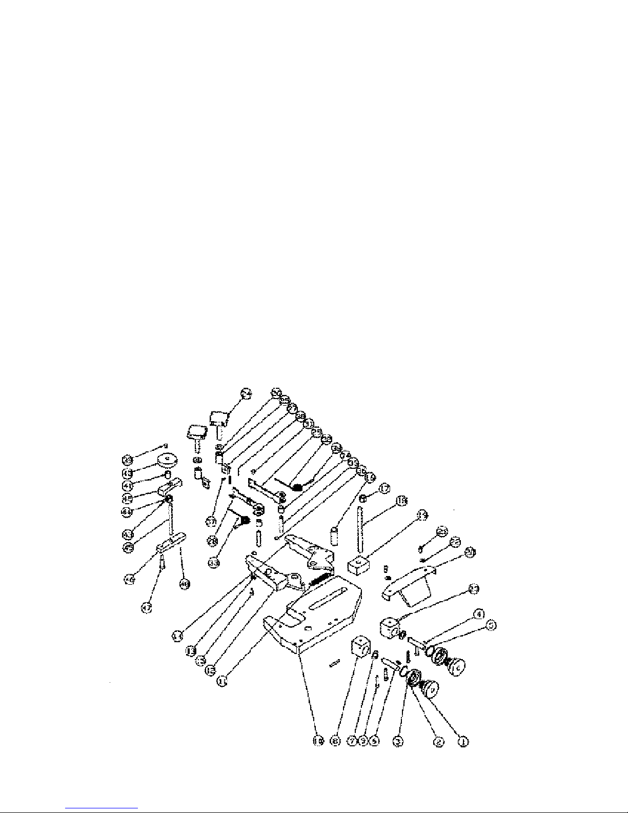
MAIN ASSEMBLY

103 Multi-Speed Brake Lathe
Replac ement Parts & Supplies - 800-553-5953 2 9
Item Part No. Description Qty.
1 000-4400-10 Handle 2
2 804-8063-01 Acorn Nut, 5/16 2
3 804-8663-24 Hand Wheel 2
4 804-8679-65 Disc Slide Plate 1
5 804-8686-36 Disc Lead Screw 1
6 804-8663-17 Disc Slide 1
7 804-8679-76 Upper Gib Lock Handle Assy 1
8 000-0102-86 SHCS 5/16-18 x 3/4 1
9 804-8692-20 Disc Slide Gib Screw 4
10 804-8663-22 Gib Plate 2
11 000-0166-08 SHCS 1/4-20 x 1.00 1
12 800-8690-47 BHCS 5/16-18 x .75 2
13 804-8686-34
1
Disc Slide Lead Screw Nut Assy
1
14 804-8663-48 Drive Chain Guard 1
15 804-8671-87 Upper Lead Screw Guard 1
16 804-8680-10 Lower Gib Lock Handle Assy 1
17 804-8668-00 Chain Assembly 1
18 804-8148-06 SHCS 10-32 x 1.75 4
19 804-8663-19 Drum Slide 1
20 804-8663-36 Drive Motor Gear Assembly 1
21 804-8663-40 Gear Link Shaft Assembly 1
22 804-8680-70 Way Cover Retaining Flange 1
23 804-8665-55 Limit Switch 1
24 804-8663-35 D.C. Gear Motor 2
25 000-0595-28 BHCS 10-32 x .375 8
26 804-8663-38 Drive Sprocket 1
27 804-8663-78 Lower Lead Screw Guard 1
28
29 804-8661-62 Electric Box 1
30 804-8686-74
2
Drum Slide Lead Screw Nut Assy
2
Item Part No. Description Qty.
31 804-8681-22 Way Cover 1
32 804-8664-20 Motor Cover Guard 1
33 804-8686-37 Drum Lead Screw 1
34 804-8680-71 Way Cover Retaining Flange 1
35 804-1200-65 BHCS 10-32 x .25 10
36 804-8679-64 Drum Slide Plate 1
37 804-8680-80 Drum Slide Spacer Block 1
38 804-8679-66 Bearing 2
39 804-8689-79 Spacer 2
40 000-7204-96 Roll Pin, 1/8 x 1/2 2
41 804-8012-68 Pointer 2
42 804-8013-29 Hex Nut 1/4-20 1
43
44 804-8665-24 Disc Hand Wheel Label 1
45 804-8689-86 Rotor Feed Lock Assembly * 1
46 000-1042-64 Hex Nut 5/16-18 4
47 804-1117-26 Drum Slide Gib Screw 4
48 000-0592-20 BHCS 5/16-18 x 1.00 1
49 804-8035-96 SSS 1/4-20 x 1/4 1
50 000-0163-14 SHCS 10-32 x 1/2 12
51 000-0165-27 SHCS 1/4-20 x 5/8 4
52 000-1154-60 Flat Washer #10 1
53
54 000-0482-91 SSS 10-32 x .25 1
55 000-0594-04 BHCS 6-32 x .37 4
56 804-8665-66 Limit Switch Cover 1
57 804-8689-87 Drum Feed Lock Assembly ** 1
58 804-8665-25 Drum Hand Wheel Label 1
59 804-8622-24 SHCS 1/4-20 x 2.75 2
* See Page 26 for Detail
** See Page 27 for Detail
1 See Page 32 for Detail
2 See Page 32 for Detail
MAIN ASSEMBLY

3 0 Replac em ent Parts & Supplies - 800-553-5953
103 Multi-Speed Brake Lathe
ITEM 45 ON MAIN ASSEMBLY DRAWING
804-8689-86
ROTOR FEED LOCK ASSEMBLY
Item Part No. Description Qty.
1 000-0595-32 BHCS 10-32 x .500....................1
2 804-8689-80 Knob ..........................................1
3 804-8689-83 Engagement Stem (Disc) ...........1
4 804-8097-68 Roll Pin, .062 x .500 .................1
5 804-8689-85 Flat Washer, 6mm.....................1
6 804-8689-84 Spring ........................................1
7 804-8689-81 Feed Engagement Block ...........1
8 804-8690-06 Dowel Pin .125 x .625 ..............1

103 Multi-Speed Brake Lathe
Replac ement Parts & Supplies - 800-553-5953 3 1
ITEM 57 ON MAIN ASSEMBLY DRAWING
804-8689-87
DRUM FEED LOCK ASSEMBLY
Item Part No. Description Qty.
1 000-0595-32 BHCS 10-32 x .500....................1
2 804-8689-80 Knob ..........................................1
3 804-8689-82 Engagement Stem (Drum).........1
4 804-8097-68 Roll Pin .062 x .500 ..................1
5 804-8689-85 Flat Washer, 6mm.....................1
6 804-8689-84 Spring ........................................1
7 804-8689-81 Feed Engagement Block ...........1
8 804-8690-06 Dowel Pin .125 x .625 ..............1

3 2 Replac em ent Parts & Supplies - 800-553-5953
103 Multi-Speed Brake Lathe
103 FRONT VIEW CONTROL BOX ASSEMBLY
Item Part No. Description Qty.
1 804-8680-40 Control Box 1
2 804-8607-40 Feed Rate Dial 1
3 804-8675-50 Function Switch 1
4 800-8675-49 Push/Pull Switch 1
5 800-8665-89 Fuse holder 1
6 800-8014-69 Strain Relief .230 3
7 800-8606-79 DC Controller 1
8 804-8653-31 BHCS #8-32 x .75 2
9 000-1095-17 Hex Nut #8-32 4
10 804-8668-20 Terminal Block 1
11 804-8680-87 Control Box Cover 1
12 804-8668-03 Receptacle 125V 1
13 804-8680-46 Control Box Label 1
14 804-8622-69 Fuse 1.0 Amp 1
15 804-8679-75 Fuse 1/2 Amp 1
16 800-8667-93 Lock Nut 1/2 NPT 1
17 804-8668-05 Self Tapping Screw 6
18 000-1261-01 Power Cord 1
19 804-8668-19 Terminal Jumper 3
20 800-8046-78 Work Light Mount 1

103 Multi-Speed Brake Lathe
Replac ement Parts & Supplies - 800-553-5953 3 3
103 CONTROL BOX ASSEMBLY

3 4 Replac em ent Parts & Supplies - 800-553-5953
103 Multi-Speed Brake Lathe
804-8680-44
SPINDLE HOUSING ASSEMBLY
Item Part No. Description Qty.
1 804-8663-65 Seal-Front 1
2 804-8680-45 Spindle 1
3 804-8084-14 Bearing Cone 1
4 804-8084-15 Bearing Cup 1
5 804-8680-43 Spindle Housing 1
6 804-8680-50 Bearing Cup 1
7 804-8680-49 Bearing Cone 1
8 804-8680-84 Spacer 1
9 804-8663-71 Seal-Rear 1
10 804-8663-56 Locknut BH 07 1
Item Part No. Description Qty.
1 804-8663-90 Draw Bar Assembly 1
2 804-8691-87 1.0” Extended Arbor (RH) 1
3 804-8685-14 Spherical Washer Set 1
4 804-8691-65 Arbor Nut 1
804-8691-88
ARBOR ASSEMBLY

103 Multi-Speed Brake Lathe
Replac ement Parts & Supplies - 800-553-5953 3 5
TOOL BAR ASSEMBLY
Item Part No. Description Qty.
1 804-8691-73 Tool Bar 1
2 000-0505-20 SSS .375-16 x .500 2
3 804-8030-07 SS .312-24 x .375 1
4 804-8691-74 Tool Bit Holder 1
5 000-0160-14 SHCS 8-32 x .625 1
6 804-3041-67 (Package of 3) 1
7 804-3041-71 Tool Holder Assembly 1
8 804-8664-42 Flange Nut 1
9 804-2043-03 Tooling Clamp Stud 1
10 804-2040-30 Tool Holder Clamp 1
11 804-2043-01 Tool Holder 1

3 6 Replac em ent Parts & Supplies - 800-553-5953
103 Multi-Speed Brake Lathe
804-8686-34
DISC SLIDE LEAD SCREW NUT ASSEMBLY
Item Part No. Description Qty.
1 804-8686-35 Leadscrew Nut Sleeve 1
2 000-1624-10 Thrust Washer 2
3 000-1624-00 Needle Bearing 1
4 804-8663-26 Nut Mount, Block 1
5 804-8663-27 Leadscrew Drive Gear 1
6 804-8668-34 SSS #10-32 x .18 4
804-8686-74
DRUM SLIDE LEAD SCREW NUT ASSEMBLY
Item Part No. Description Qty.
1 804-8686-35 Leadscrew Nut Sleeve 1
2 000-1624-10 Thrust Washer 2
3 000-1624-00 Needle Bearing 1
4 804-8663-26 Block Nut Mount 1
5 804-8663-27 Leadscrew Drive Gear 1
6 804-8668-34 SSS #10-32 x .18 4

103 Multi-Speed Brake Lathe
Replac ement Parts & Supplies - 800-553-5953 3 7
804-8663-40
GEAR LINK SHAFT ASSEMBLY
Item Part No. Description Qty.
1 804-8665-51 Gear Shaft Assembly 1
2 804-8663-83 Oilite Bearing 1
3 804-8663-43 Gear Link Support 1
4 804-8663-38 Drive Sprocket 1
5 000-0482-91 SSS #10-32 x .25 2
6 804-1290-02 Oilite Thrust Washer 1
3 8 Replac em ent Parts & Supplies - 800-553-5953
103 Multi-Speed Brake Lathe
804-8691-68 DISC CLAW ASSEMBLY
Item Part No. Description Qty.
1 804-8689-51 Micrometer Knob 2
2 804-8689-52 Zeroing Sleeve 2
3 804-8659-49 Feed Dial Label 2
4 000-7300-41 Woodruff #5 Key 2
5 804-8689-78 Spring Washer 2
6 804-2042-70 Feed Screw 2
7 804-1258-10 Finger Spring Washer 2
8 804-8690-24 Feed Dial Block 2
9 000-0166-08 SHCS, 1/4-20 x 1.25 4
10 804-8690-23 Claw Base Plate 1
11 804-1405-35 Spring 1
12 804-8678-55 Tool Holder LH 1
13 804-1292-79 Tool Bit w/Spring Clamp 2
14 804-8678-54 Tool Holder RH 1
15 000-0165-27 SHCS, 1/4-20 x .62 2
16 804-1258-12 Dowel Pin, .75 x 2.00 1
17 804-8664-42 Flange Nut 1
18 804-2043-03 Tool Clamp Stud 1
19 804-2058-49 Clamp Block 1
20 804-2043-20 Guard 1
21 000-0165-27 SHCS, 1/4-20 x 5/8 2
22 804-8684-34 Rubber Seal Washer 4
23 804-1199-25 Dowel Pin, 3/16 x 1.50 2
24 804-8693-77 Hand Lock Knob 2
Item Part No. Description Qty.
25 804-8691-28 Knob Spacer 2
26 804-1407-54 Washer 2
27 804-2052-31 Shoe 2
28 804-8691-32 Dampener Arm LH 1
29 804-8691-33 Dampener Arm RH 1
30 804-1094-24 Roll Pin, .156 x 1.00 2
31 804-8691-36 BHCS 10-32 x 1.50 4
32 804-8691-31 Dampener RH Spring 1
33 804-8691-30 Dampener LH Spring 1
34 804-8691-34 Spring Bushing 2
35 804-8035-72 Dowel Pin, .375 x 2.00 2
36 804-8012-92 O-Ring, .312 x .062 2
37 000-0593-82 BHCS 6-32 x .25 2
38 804-8691-35 Spring Grip Knob 2
39 000-0595-32 BHCS 10-32 x .50 1
40 804-8689-80 Knob 1
41 804-8691-28 Spacer 1
42 804-8691-69 Clamp Bar 1
43 804-8668-34 Socket Set Screw 1
44 804-8691-72 Machined Nut 1
45 804-8691-71 Machined Stud 1
46 804-8691-70 Lower Clamp Bar 1
47 000-0598-38 Stripper Bolt 1
48 804-1094-24 Roll Pin 1
NS
800-8083-74 Hex Nut 10-32 Std 4

103 Multi-Speed Brake Lathe
Replac ement Parts & Supplies - 800-553-5953 3 9
804-8665-29
DELUXE BENCH ASSEMBLY for 103 BRAKE LATHE
804-8665-47
BASIC BENCH
NOTE: Does not include Items
No.’s 5 & 6 as shown above.
IMPORTANT:
Inspect the shipment of your bench for evidence of damage before signing the bill of lading. A signed bill of lading indicates the shipment was received in good condition.
Contact KW Products (Kwik-Way) concerning any parts
shortages.
PARTS LIST
Item Part No. Description Qty.
1 804-8665-32 Leg 2
2 804-8665-31 Shelf 1
3 804-8665-38 Lower Tool Board 1
4 804-8665-30 Top 1
5 804-8665-40 Upright 2
6 804-8665-39 Upper Tool Board 1
7 804-8665-60 Decal (Not Pictured) 1
8 804-8665-53 Chip Tray (Not Pictured) 1
HARDWARE
000-0101-54 1/4-20 x 1.75 Machine Bolt 12
000-0100-14 1/4-20 x .50 Machine Bolt 18
000-1020-08 1/4 Hex Nut 30
000-0105-88 3/8-16 x 2.00 Machine Bolt 4
804-8033-25 3/8 Hex Nut 4
000-1150-45 3/8 Flat Washer 4
804-8665-50 Rubber Pads 4
804-8085-56 Hooks for Tool Boards 22
A S S E M B LY I N S T R U C T I O N S
(If lathe is equipped with outboard support, assemble according to
instructions on Page 36.
1. Assemble items 1 thru 6. Items are assembled in numerical
order using 1/4-20 x .50 bolts and nuts for all parts except 5 and
6 which use the 1/4-20 x 1.75 bolts and nuts. Leave all fasteners
loose until all parts are assembled.
2. Tighten all fasteners securely.
3. Place the four rubber pads in line with the four holes in the top
of the bench. Using proper lifting equipment place the 103
Brake Lathe on top of the pads.
4. Fasten the lathe to the bench using the four 3/8-16 x 2.00 bolts,
nuts and washers. Set the Chip Tray to the left of the lathe.
5. Arrange the hooks on the upper and lower tool board as desired.
A
5
6
4
3
1
1
2
A
NOTE:
A - use 1/4-20 x 1.75 Machine Bolt with Nut
1 thru 6 - use
1/4-20 x .50
Machine Bolt with Nut

4 0 Replac em ent Parts & Supplies - 800-553-5953
103 Multi-Speed Brake Lathe
804-8692-14
OUTBOARD SUPPORT ASSEMBLY
Item Part No. Description Qty.
1 000-0105-53 HHCS 3/8-16 x 1.25 2
2 804-8030-61 Lock Washer - 3/16” 2
3 804-8690-92 Pillow Block Bearing 1
4 804-8682-67 Support Bearing Slide 1
5 804-8682-69 Locking Collar 1
6 804-8682-66 Base Weldment Stand 1
7 000-1035-35 Nut 1/2-13 4
8 000-1150-53 Washer - 1/2” 4
9 804-8690-93 Leveling Pad Screw 4
10 000-1150-45 Washer 2
804-8691-92 Arbor Assembly
1 804-4041-74 Washer 1
2 804-1244-05 Groove Pin 1
3 804-8691-90 Nut LH 2" Arbor 1
4 804-8691-86 Arbor 2" Extended 1
804-8691-92


Kwik-Way Products Inc.
500 57th Street, Marion, IA 52302 USA
319-377-9421
319-377-9101 (FAX)
800-553-5953
www.kwik-way.com
service@kwik-way.com
Copyright © Kwik-Way Products Inc. 2005 All Rights Reserved
 Loading...