

Kwik Lok 086A, 086AS Installation Manual
086A 04 14
TYPE
086A and
086AS
SEMIAUTOMATIC
BAG CLOSER
INSTRUCTION
MANUAL
TYPE SERIAL NO.
MODEL
EXECUTIVE OFFICE P.O. BOX 9548 YAKIMA, WA. 98909
®
TELEPHONE: 1-800-688-5945 or (509) 248-4770
®
CORPORATION
FAX: (509) 457-6531
Internet: www.kwiklok.com

086A and 086AS CLOSER
TABLE OF CONTENTS
I SPECIFICATIONS...............................................1.1 - 1.2
II OPERATION........................................................2.1 - 2.2
III ADJUSTMENTS..................................................3.1 - 3.8
IV TROUBLE SHOOTING........................................4.1 - 4.3
V PARTS IDENTIFICATION....................................5.1 - 5.11
VI WIRING................................................................6.1
APPENDIX
BAG LENGTH FORMULA....................................A
BAGNECK TRIMMER OPERATION.....................B - E
SUGGESTED SPARE PARTS / WARRANTY.......F
RETURNED MATERIALS AUTHORIZATION.......G
SECTION HEADING PAGE
GENERAL SAFETY INFORMATION
Be sure the following safety instructions are read, understood and become a part of daily
practice when operating or maintaining the closing head.
1. Do not attempt to operate the closer until you understand its function. Study the manual
carefully.
2. Keep all foreign material away from the drive system.
3. Keep fingers out of the closer and away from any moving parts.
4. Disconnect the power cord before making any adjustments or maintenance. All
moving parts must be completely stopped before continuing. All adjustments are made
with power disconnected.
5. The closer is normally operated from a counter or table. While the closer is very stable
when operated from a flat a solid surface, care should be taken not use it in a way that
could cause it to tip or fall from the operating surface.
® 2014 KWIK LOK CORPORATION
Kwik Lok® and Striplok® are trademarks of Kwik Lok Corporation
The shape of the closure is a trademark of Kwik Lok Corporation
086A 04 14

P 1.1
SECTION I
Specifications
086A 7 01
THE TYPE 086A and 086AS
MACHINE
SEMIAUTOMATICALLY CLOSES
PLASTIC BAGS
WITH THE STRIPLOK
® CLOSURE
OR THE STRIPLOK CLOSURE LABEL
A. The closing machine designated Type 086A can
run standard R, RJ, and S series closures, and
series L and U labels.
B. The system will close a wide range of product
size variations. The Striplok closures are available
in many closure opening sizes to accommodate a
large number of variations in bag width and film
material thickness.
Upon request and upon receipt of sample bags,
the factory will gladly recommend the proper
closure opening sizes. Use the bag length formula
found in the appendix of this manual to help
determine the proper bag length needed.
C. A suggested spare parts inventory is listed in the
appendix. To save valuable time, it is recommended that an adequate supply of these parts be kept
on hand for needed repairs.
P 1.2
SECTION I
Specifications
086A SEMIAUTOMATIC BAG CLOSING
MACHINE SPECIFICATIONS
086A 06 10
TYPE MODEL
CLOSURE
086A
L Labels, medium and heavy duty
U Labels, medium and heavy duty
RJ
R and S
300
400
100
200
086AS
L Labels, medium and heavy duty
U Labels, medium and heavy duty
RJ
R and S
300
400
500
CR and CS Labels
CR and CS Labels
500
100
200
Up to
30 Bags/Min.
SPEED
1. The 086A semiautomatic closer comes standard
with mounted rubber feet.
Optional suction cup feet are available.
2. The 086A is available for use with the following
electrical power:
115 VAC, 60 Hz, 1amp, single phase
220 - 240VAC, 50 Hz, .38 amp, single phase
3. The model 086AS is a stainless steel version of the
086 bag closer.

P 2.1
SECTION II
Operation
086A 04 11
Power switch
Ready light
Run switch
A. OPERATING SEQUENCE:
(Figure 2.1)
The closer is ready to run when the closure is in
closing position, the power switch is in the ”ON”
position, and the ”READY” light is on. When the
closed bag and closure are removed from the
closure track, the machine completes the closing
cycle placing the next closure in closing position.
The machine is again ready for the next bag.
During the completion of the closing cycle the
”READY” light will go off momentarily.
If no closure is available to move into the closing
position, the machine will continue to cycle and the
”READY light will flash repeatedly until the run
switch is turned to the ”STOP” position.
The power switch and light must be off to cut
off power to the two sensor switches. Utilizing
the power switch instead of the run switch may
result in the machine not stopping in the neutral
position as required for loading the closure
strip. Use the power switch when clearing the
machine of debris or preforming minor service
work.
1. Plug in the closer.
2. Press the power switch to ”ON”.
3. Slide the closure strip into the closure track until
the strip stops (refer to part B in this section).
4. Press the run switch to ”RUN” . A closure will
move into the closing position, if one is not
already there, and the ”READY” light goes on
indicating the the closer is ready to close.
5. Close the bag and remove it from the closer
(refer to part C in this section).
6. The closer cycles to position a new closure into
the closing position, ready for the next bag.
The ”READY” light will go off momentarily as
the closure is loading.
7. If no closure is available to move into the
closing position, the machine will cycle and the
”READY” light will flash on and off repeatedly
until the run switch is pressed to ”STOP”. The
machine will then cycle back to neutral and
stop. The machine at this point is again ready
to close.
B. LOADING A ROLL OF CLOSURES:
1. Cycle the closer until there are no closures left
in the closure track. Avoid cycling the closer
more than necessary when there is no closure
in the closing position.
2. Move the run switch to “STOP” so the
mechanism is properly positioned.
3. When closing with closures, insert the closure
hub into a new roll of closures. Be certain the
closures feed forward from the bottom of the
roll.
When closing with labels, insert the closure
hub so that the label of the closure is right
side up when the closure strip is in the closure
track.
4. Install the hub and roll.
Figure 2.1
SECTION II
Operation
P 2.2
5. Remove the masking tape and feed the end of
the strip into the closure track until the first
closure has passed the check and is against
the stop.
6. With the Power switch in the ”ON” position,
press the run switch to “RUN”. The closer will
cycle once and move a closure into the closing
position. The closer is now ready to close bags.
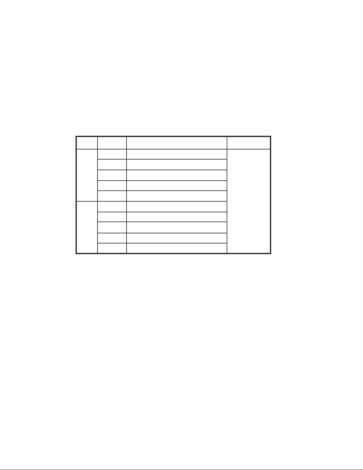
C. CLOSING BAGS:
(Figure 2.2)
1. Grasp the bag as shown. Spin the bag to twist
the bag neck. Twisting the bag helps the
material to enter the closure smoothly.
2. The lower hand should form a “V” to trap all of
the bag material. This helps to completely
insert the bag material into the closure opening.
3. Do not jam the bag material straight into the
closure opening. The top hand should lead the
bottom hand. Follow up with the lower hand
until all of the bag neck is in the closure. A tight
package is accomplished by holding the
contents of the bag snugly up against the
underside of the closure track.
4. Remove the closed bag with a horizontal
motion.
086A 08 08
Figure 2.2
SECTION III
Adjustments
P 3.1
086A 08 08
THE FOLLOWING ADJUSTMENTS ARE TO BE
PERFORMED WITH THE CLOSER ELECTRICAL
POWER DISCONNECTED.
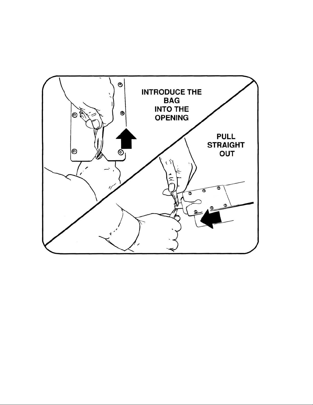
A. CLOSURE TRACK ASSEMBLY REMOVAL:
Some of the adjustments described in this section
require removal of the closure track assembly.
1. Remove the side access cover (Figure 3.1).
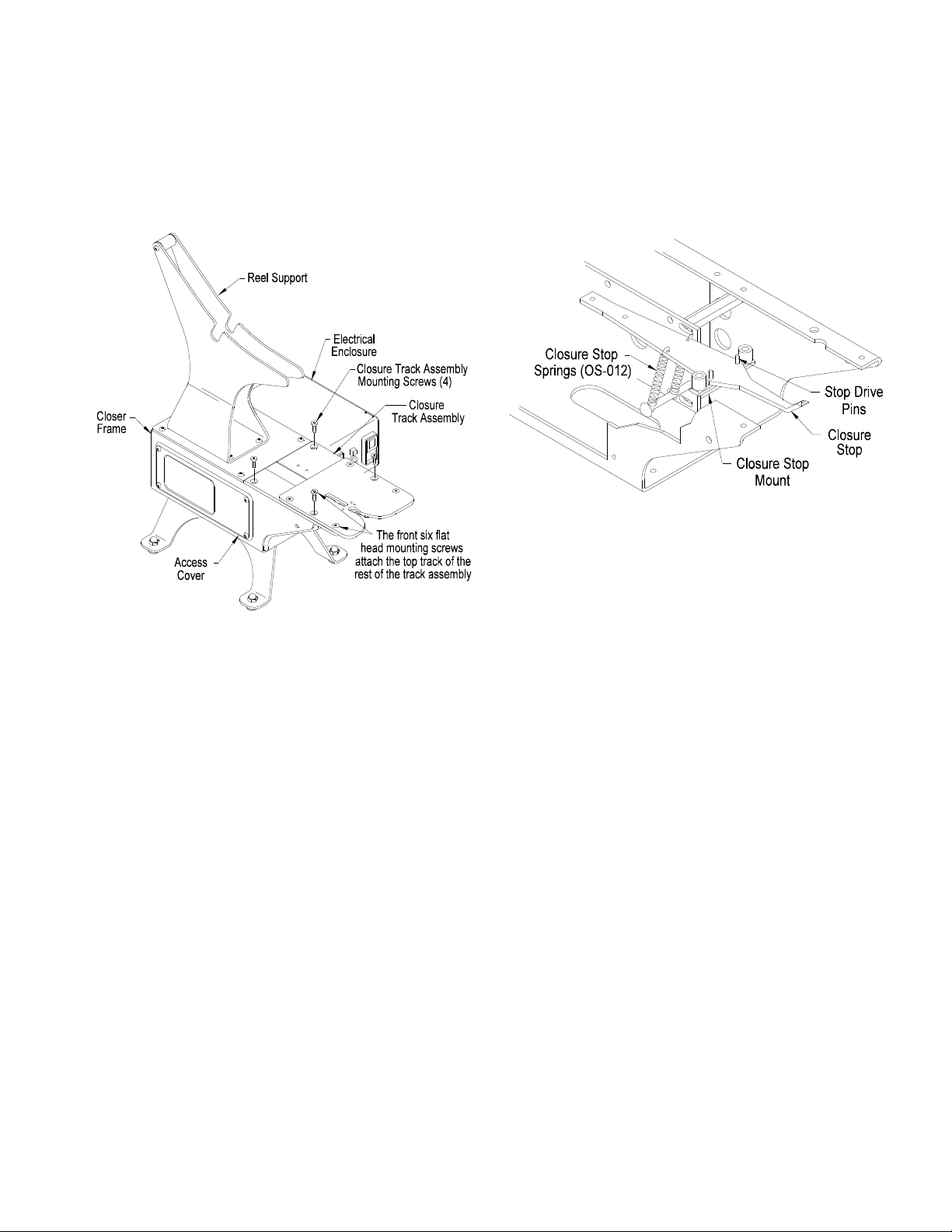
2. Disconnect the two gold colored closure stop
springs (OS-012) from the lower spring anchor
screw (Figure 3.2). When the springs are
reattached be careful not to stretch them.
3. Remove the four flat head mounting screws
which attach the closure track assembly to the
closer main frame.
When remounting the track assembly, tighten
the four mounting screws evenly.
4. Lift the closure track assembly slightly and
depress the tip of the pick to disengage it from
the closure track.
5. Raise the closure track assembly slightly off the
frame and disconnect the two wire leads from
the sensor lever limit switch.
To remount the closure track assembly, reverse the
above procedure. Before closing the access cover,
check to see that there are no pinched wires or
wires routed close to moving parts.
B. TOP CLOSURE TRACK REMOVAL:
The top of the closure track can be removed from
the closer while the closure track assembly remains
attached to the closer mainframe. This can be done
to expose the slot that the closures move through.
The closure track can be inspected and cleaned if
needed (Figure 3.1).
1. Remove the front six flathead screws from the
track top. Note the different screw lengths upon
removal.
2. Remove the top of the closure track from the
rest of the track assembly.
Figure 3.2
Figure 3.1

SECTION III
Adjustments
P 3.2
086A 05 11
C. REMOVE THE FRONT SHIELD:
Some of the adjustments described in this section
require removal of the front SHIELD.
DISCONNECT POWER.
1. Remove the side access cover from the closer
frame.
2. Remove the two self tapping phillIps screws
(P23-00291) used to fasten the sides of the
SHIELD from the closer frame.
3. Loosen (turn clockwise) the two SHIELD
mounting screws at the bottom of the closer
frame.
4. Press lightly, from inside the closer frame, on
the backside of the SHIELD to remove it.
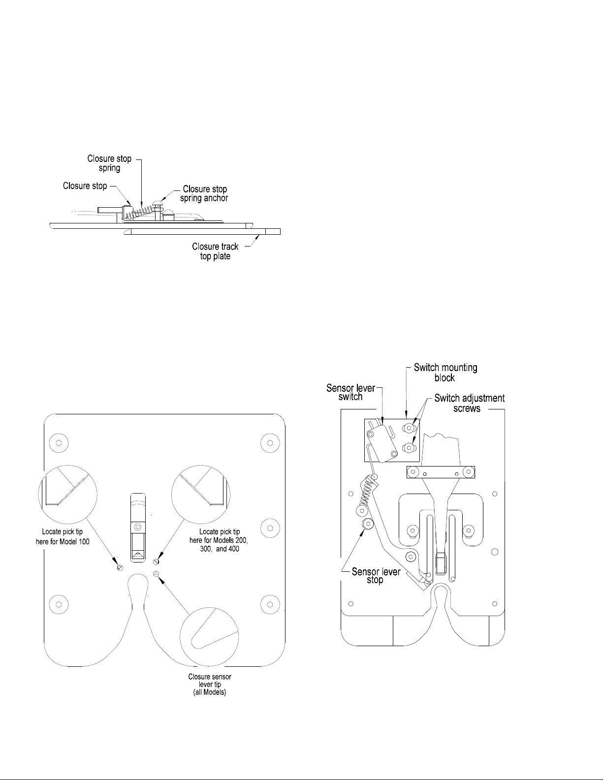
D. CHECK POSITION:
The check stops the closure strip from moving
backward while the pick retracts.
Depending on the model closer there are two
different mounting locations for the check.
Refer to Figure 3.3 to further understand the check
mounting position. For this adjustment the closure
track must be removed from the closer.
For 086 Model 100 the check is mounted in the
forward mounting holes (the two mounting holes
closest to the front of the closure track).
For 086 Models 200, 300, or 400, the check is
mounted in the back mounting holes (furthest from
the front of the closure track).
1. With the check mounted in the correct
holes, and the mounting screws loose, slide
the check forward toward the front of the closure
track to the end of the mounting slots.
2. Tighten the mounting screws.
E. CLOSURE STOP POSITION:
The end closure is separated from the closure strip
when the closure stop limits the travel of the second
closure in the strip while the pick continues to
advance the first closure.
As with the position of the check, the closure
stop mount is located in a specific way depending
on the closer model being adjusted.
1. For 086 Model 100 the closure stop mount is
mounted as shown (Figure 3.3 upper view).
Figure 3.3
Closure track assembly as viewed from the underside.
SECTION III
Adjustments
P 3.3
086A 08 08
For 086 Models 200, 300, or 400, the stop
mount is mounted as shown (Figure 3.3 lower
view).
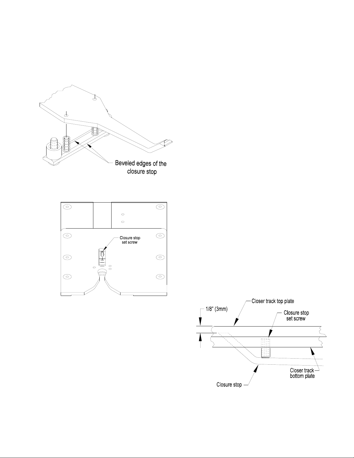
2. Be sure the beveled edges of the mount are
against the closure stop as noted in Figure 3.4.
The closure stop tip must be centered in the slot
located in the closure track for it.
3. Slightly loosen the stop mount mounting screws.
4. Move the closure stop tip side to side until it is
centered in the slot.
5. Tighten the mounting screws.
6. Turn the closure track assembly over so it is
right side up in your hands. Again check the
position of the closure stop tip as this is the way
the closure track is oriented during operation.
Readjust if needed.
F. CLOSURE STOP SET SCREW ADJUSTMENT:
When properly adjusted the closure stop setscrew
sets the height of the stop so the second closure in
the strip is stopped while the leading closure
continues to move ahead and so is separated from
the closure strip. The closure track assembly need
not be removed to make this adjustment. Adjust as
follows:
1. Remove any closures from the track.
2. Locate the top of the set screw (Figure 3.5).
3. Turn the set screw in or out to lower or raise the
tip of the stop until it is 1/8” (3mm) below the top
of the track top plate (Figure 3.6).
Figure 3.5
Figure 3.4
Figure 3.6
SECTION III
Adjustments
P 3.4
086A 08 08
G. SENSOR LEVER SPRING:
The sensor lever spring is designed to apply force
to the sensor lever tip against the side of the closure
as well as upward against the underside of the
closure track. For the spring to operate correctly it
must be mounted as shown in Figure 3.7.
H. SENSOR LEVER STOP ADJUSTMENT
(Figures 3.8 & 3.9):
The sensor lever stop is a bushing which limits the
travel of the sensor lever when no closures are
present. The bushing is secured under a 10-32
button head screw. There is clearance between the
two so the position of the bushing can vary. When
no closures are present, the sensor lever tip should
be centered below the inspection hole in the top
track.
1. Loosen the mounting screw and move the
bushing as needed.
2. Retighten the mounting screw.
Figure 3.7
Figure 3.8
Figure 3.9
Closure track assembly as viewed from the underside.
SECTION III
Adjustments
P 3.5
086A 08 08
I. SENSOR SWITCH ADJUSTMENT:
The sensor switch detects whether or not there is a
closure in the closing position. When a closure
moves into the closing position, the sensor switch
stops the motor at the end of the cycle. When the
closure is removed, the switch starts the motor.
The switch should turn on and off midway between
the positions of the sensor lever when it is resting
against the sensor lever stop and when it is resting
against the side of a closure.
1. Check to see if the sensor lever stop is adjusted
correctly part H above.
2. Turn the closure track upside down.
3. Feed a short strip of closures (4 or 5) through
the track until the leading edge of the first
closure just slides past the sensor lever then
back out until the closure is free of the sensor
lever. Continue to slide the strip back and forth
while listening for an audible “click” indicating
that the switch is turning on and off. If the strip
of closures moves forward so far that it can’t
back up , push it out of the front of the track
and start over. Adjust if needed as follows.
4. Slightly loosen the two button head screws in
the switch mounting block (Figure 3.9).
5. Move the switch assembly toward or away from
the sensor lever. Listen for an audible “click” of
the switch as it turns on and off.
6. Tighten the mounting screws when the switch
actuates as described above.
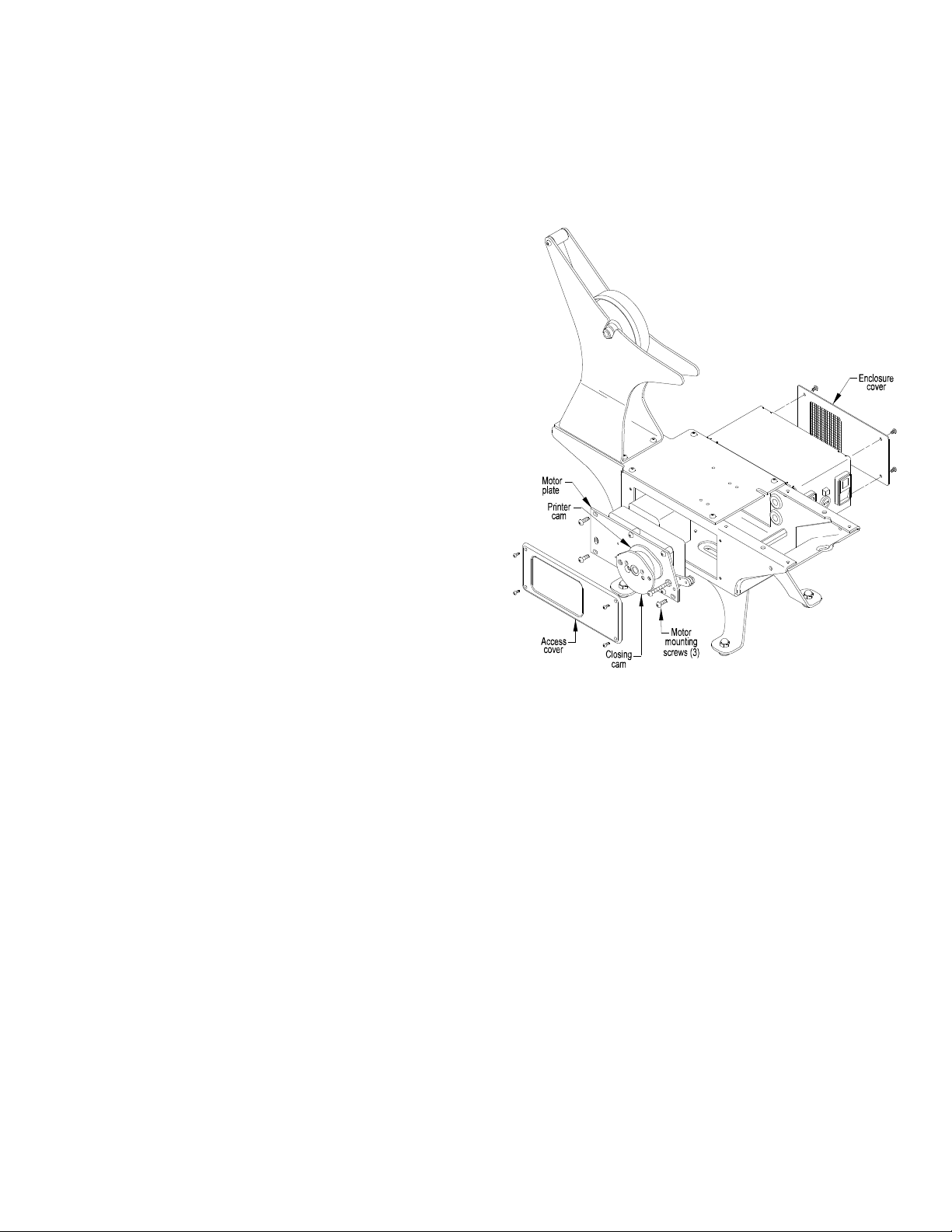
J. MOTOR REMOVAL:
(Figure 3.10):
Any time the three button head screws which are in
the slots of the motor mounting plate are disturbed,
the pick position must be checked. See part K this
section.
The motor, motor mounting plate, cam assembly,
cam switch block and accompanying limit switch can
be removed and reinstalled as an assembly.
Component adjustment to this assembly can be
made while the assembly is out of the frame of the
closer. Remove the motor assembly as follows:
1. Disconnect power to the closer.
2. Remove the electrical enclosure cover.
3. Disconnect the two motor wires from the run
switch.
4. Remove the left side access cover from the
frame.
5. Remove the closure track assembly. See part A
in this section.
6. Remove the top plate.
7. Disconnect the pick spring (OS-117) from the
pick.
Figure 3.10
SECTION III
Adjustments
P 3.6
086A 12 13
8. Disconnect the cam switch electrical leads.
9. Remove the three mounting screws from the
slotted holes in the motor mounting plate. Refer
to part J this section for readjustment.
10. Remove the motor assembly through the top of
the closer frame.
11. To reinstall the motor assembly reverse these
steps.
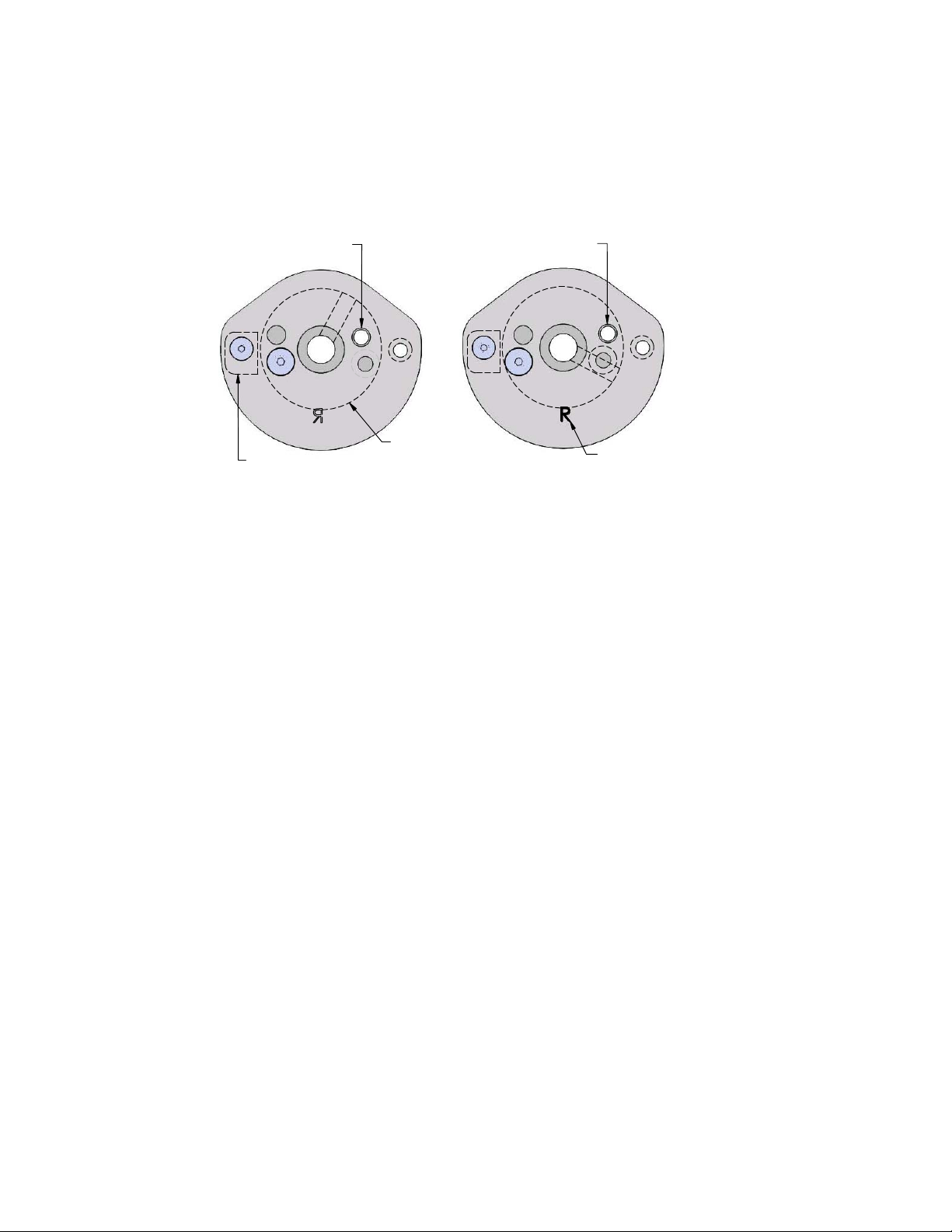
K. PICK / CLOSURE LOCATION:
The pick advances the closure strip and locates the
leading closure in the bag closing position. To verify
whether the pick stops in the correct position, check
and adjust as follows:
1. Remove any closures from the closure track.
2. Verify that the pick is at the end of its travel. To
do this plug in the closer. turn the rocker switch
to “RUN” and then to “STOP”. The motor will
stop with the cam and pick in their proper
“parked” positions.
3. With the motor stopped, disconnect the power
cord.
4. Determine the correct inspection hole for the
model for your closer (Figure 3.8). The tip of
the pick should be visible in half of the
inspection hole as shown. Reposition the pick if
needed as follows:
BE SURE THE POWER IS DISCONNECTED.
5. Remove the side access cover.
6. Loosen the four button head screws mounted in
the slots of the motor mounting plate.
7. Slide the motor assembly until the pick is in the
proper position when viewed through the
inspection hole (Figure 3.8).
8. Tighten the mounting screws and again check
the pick position. Reattach the access cover.
Figure 3.11
Pick mounting
location
Cam hub
Switch cam
(located on the
hub side of the cam)
Pick mounting
location
Cam is marked to
assist with assembly
 Loading...