

Kwikee Level Best 2000, Level Best 2010, Level Best 3000, Level Best 30130 Operation Manual
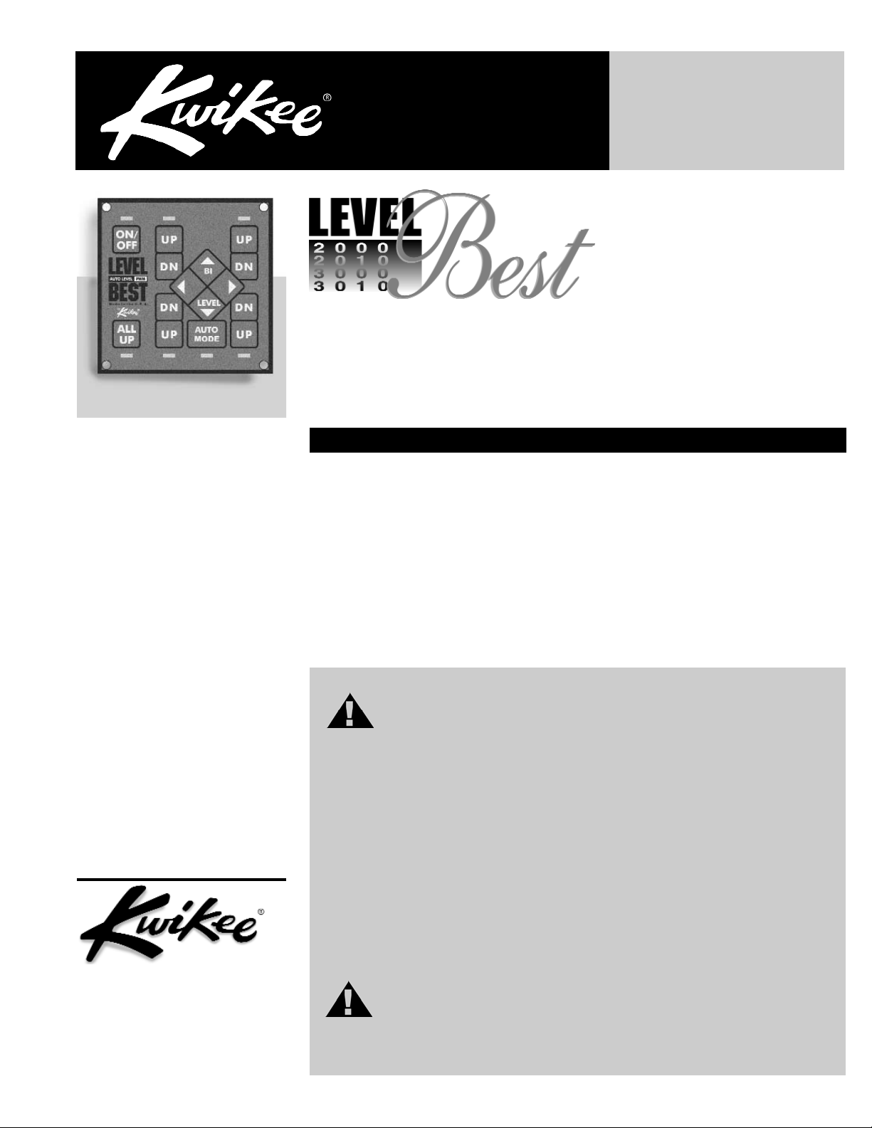
Table of Content
Page
Introduction 1
Safety Information 1
Operation 2
Control Panel 3
Manual Mode 3
Auto Mode 3
Stabalizing 4
Retracting Jacks 4
Setting Level Sensor 5
Care and Maintenance 5
Trouble Shooting Guide 6
Error Codes 6
Control Panel Jumper 7
Limited Warranty 8
Operation
Guide
Operation Guide
Products Company, Inc.
230 Davidson Avenue
Cottage Grove, Oregon 97424
(541) 942-3888
www.kwikee.com
© 2003 Kwikee Products Co., Inc.
Kwikee Doc #1421901 Rev. Feb. 2004
Hydraulic Leveling Systems #2000, #2010, #3000, and #30130
The Level Best leveling and stabilizing system is an electronically controlled/hydraulically operated unit that consists of a 12 volt DC powered motor/pump/manifold assembly
with fluid reservoir, hydraulic hoses, four hydraulically operated jacks, a control unit with
switch panel, and optional level sensor unit and pressure sensor. It is designed to meet
the varying requirements of vehicles ranging from class “C” motorhomes to the large
class “A” motorhome.
If, after thoroughly reading this manual, you still have questions in regard to the operation and maintenance of the Level Best system, please contact the Kwikee Service
Department at 1-800-736-9961.
WARNINGS
Do not use the Level Best system as a lift for changing tires or working
under the vehicle.
Never check for hydraulic fluid leaks using your hands and/or any other body part. The
leaking fluid is under pressure and is capable of cutting and penetrating your skin
resulting in severe injury.
When extending the rear stabilizers, do not lift the wheels beyond ground contact. This
overrides the braking effect of both the transmission park and parking brake. Without
this braking, it is possible for the vehicle to roll unexpectedly forward (or backward) off
the jacks. This could cause severe injury or even death.
Holding a control switch in the "extend" or "retract" position for a time period longer
than necessary to fully extend or retract the hydraulic cylinders, can cause overheating
and damage to the pump motor as well as the electrical components.
Do not use the leveler as an emergency brake, They are not designed for any type of
vehicle braking purpose.
Do not use the levelers on icy or slick surfaces on which the foot pads may slip.
IN THE EVENT OF ACCIDENTAL EXTENSION
1. Bring the vehicle to a safe and complete stop as soon as possible.
2. Turn the leveling systems power switch on and press the all up switch.
3. Visually inspect the vehicle undercarriage for any problems.
Introduction
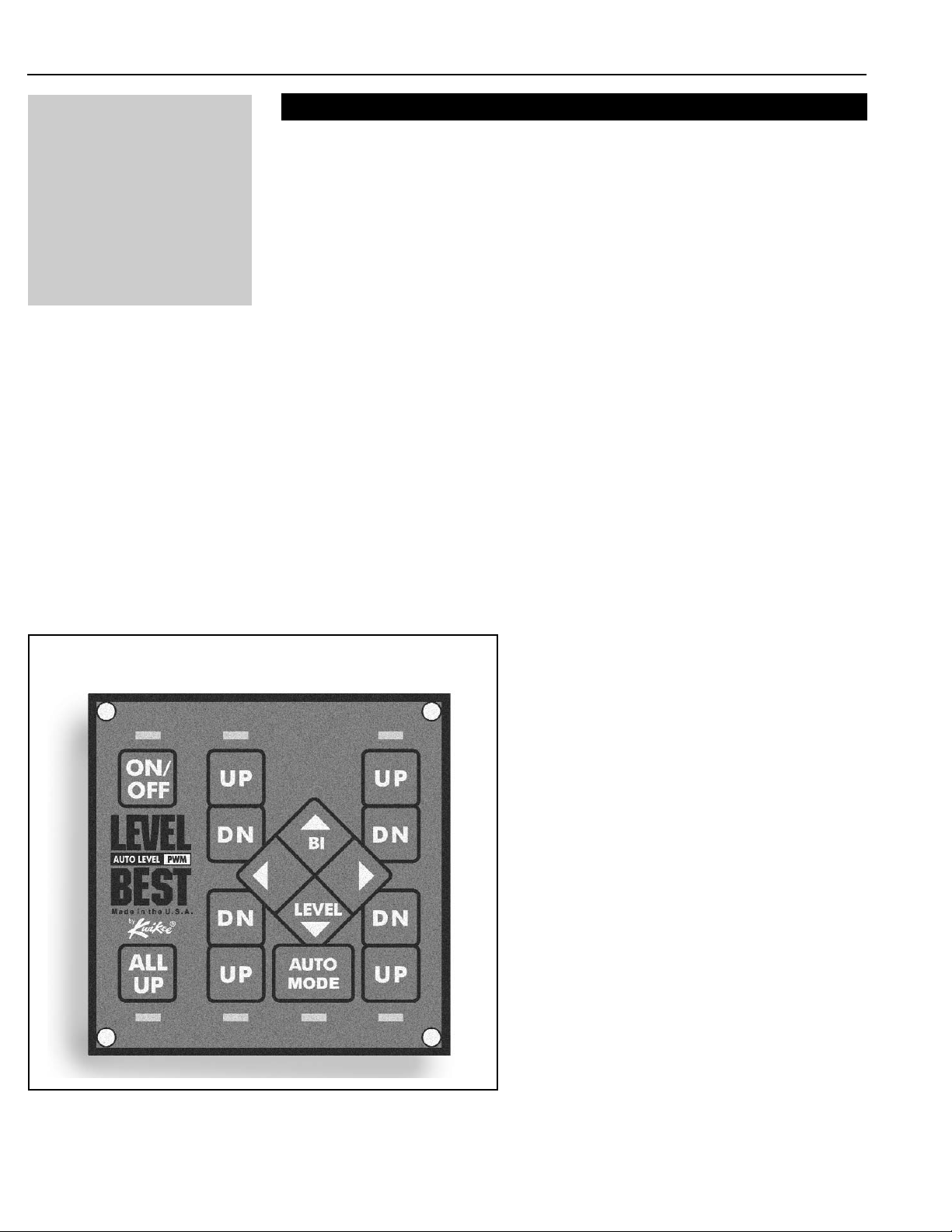
The control panel consists of switches and light
emitting diode indicators (Figure 1).
The switches include main power ON/OFF, all jacks
retract (ALL UP), a diamond shaped switch for bilateral leveling
(BI-LEVEL), and four (UP/DN) switches for
independent extension and retraction of the jack
legs. The position of the UP/DN switches correspond
to the postion of the jack legs on your motor home,
with the front of the vehicle indicated by the top of
the panel.
The AUTO LEVEL switch only appears on motor
homes equipped with fully-automatic leveling.
Figure 1: Fully-automatic touchpad control panel shown.
The Level Best system performs the dual function of leveling the vehicle and, once a level
plane has been achieved, stabilizing the vehicle. When leveling the vehicle, it may not be
necessary to use all of the leveling jacks however, to stabilize the vehicle, all jacks should be
extended to contact the ground.
SITE SELECTION
1. When selecting a site for parking the vehicle, choose a spot that is as flat as possible this will minimize the extent of leveling.
2. Check that the area under the vehicle is free from any obstacles that might interfere with
the operation of the levelers. Check the ground surface to assure the leveler feet have a flat
solid surface for contact. When parking on grass, soft dirt and/or uneven terrain, it is
advisable to extend the surface area of the leveler feet by using pads. These pads can be
from 3/4" plywood, cut into 12" squares.
NOTE: In occasional adverse driving conditions, it is possible for mud, ice and other debris to
accumulate around the leveler units. This debris may interfere with the operation and should
be cleaned off prior to using the system.
CAUTION: Do not compensate for uneven terrain by using pads that are thicker than
3". Pads that are thicker than the leveler's vertical ground clearance can prevent
breaking contact with the ground when retracting. This can result in damage to both
the levelers and the vehicle.
NOTE: To prevent improper
operation of the leveling
system, which could result in
damage to the levelers and/or
the vehicle itself, read the
operating instructions
carefully before using the
leveling jacks.
Operation
Level Best Operation Guide Page 2

To stabilize the vehicle once it has been leveled, any unused leveler must be extended into
firm contact with the ground. Accomplish this by using the appropriate individual leg leveling
switch so as not to affect the level of the coach.
CAUTION: Overextending the levelers during stabilizing will cause the vehicle to
become unlevel and result in a loss of stability. If a leveler has been overextended,
press the ‘up’ portion of the respective switch until the vehicle lowers into the level
plane again. Do not attempt to use the other levelers to raise the vehicle to a higher
level plane.
Control Panel Functions
Manual Leveling
The ON/OFF switch, located in the upper left hand corner, controls the supply of power for all
panel functions, activation of this switch is indicated by its green LED.
The ALL UP (leg retract) switch is located in the lower left hand corner of the control panel.
Activation of this switch causes all legs to retract to the travel position. When the retract
sequence is completed the ALL UP LED will turn green to indicate that it is now safe to move
the motor home.
The diamond shaped BI-LEVEL switch, located in the center of the panel, activates the
extension of the leveling jacks in pairs. Use of this switch greatly simplifies the leveling
process and significantly reduces the amount of stress created by the leveling process on the
motor home. Operation of this switch illuminates the yellow LED’s corresponding to the jacks
that are being activated. The LED will illuminate in manual version only.
The four UP/DOWN switches control the leveling jacks independently. Pushing these
switches operates the corresponding jack causing it to retract (UP) or extend (DN). Operation
of this switch lights the yellow LED corresponding with the jack activated. The LED will
illuminate in manual version only.
Level Best Operation Guide Page 3
SEMI-AUTOMATIC FUNCTION When an AUTO MODE sensor is connected to
a manual control, the jack indicator lights act as an indicator of the level
condition of the coach. A light that is ‘on’ indicates the high corner of the
coach. Push the BI-LEVEL pair button corresponding to the end of the coach
you would like to raise. When the light comes ‘on’, stop the action of that
button. In this way the jack indicator lights act as a bubble-level, indicating
the level condition of the coach.
FULLY-AUTOMATIC FUNCTION Coaches equipped with AUTO MODE
can be operated the same as manual or semi-automatic versions. The fully-
automatic unit functions the same until the AUTO MODE switch is pressed.
Pushing the AUTO MODE switch causes the system to extend a pair of jack legs
to the ground. Next the other pair of legs is extended to the ground and the system
begins the auto level sequence. During the auto level sequence the system will run
one to three of the jacks depending on the level condition of the coach. On completion,
the system will check the level condition of the coach and either re-run the sequence
or display a green LED light under the AUTO MODE button to indicate that the
sequence is complete. Typical coach level capability is 0.3 degrees from side to
side and front to rear.
Automatic Leveling
 Loading...