

Kwikee 2000, 2010, 3000, 3010 Installation Instructions Manual
LEVEL BEST
CONTROL REPLACEMENT
Systems 2000, 2010, 3000, 3010
Installation
Instructions
Kit 906915110
© 04/03 Kwikee Products Co., Inc.
Kwikee #1422271
Before beginning any work, read
these instructions.
Disconnect the chassis battery
before beginning any work on the
Level Best System.
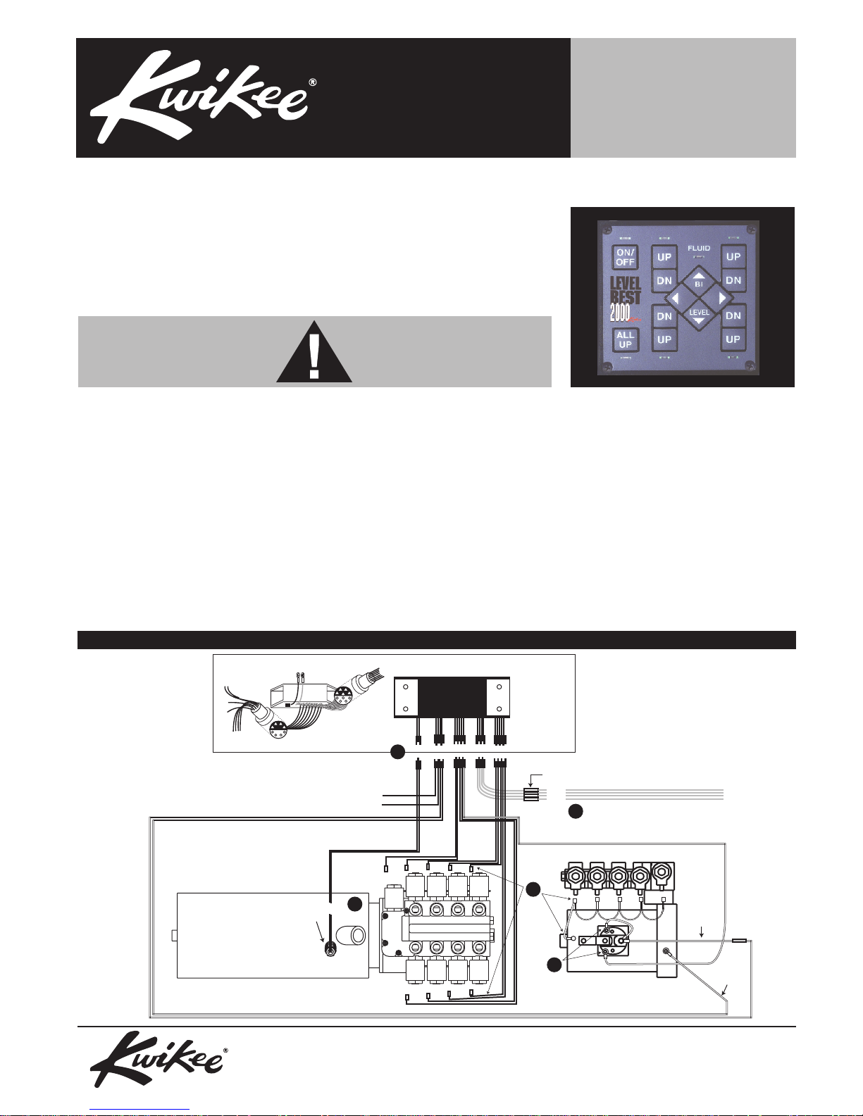
Removing the old control and wiring (Refer to Figure 1 for Steps 1 through 5.)
Disconnect the positive cable from
the battery before beginning any
work.
1. Cut the wires going to the Fluid
Level Sensor approximately 1 to 2
inches from the sensor.
2. Remove the wires attached to the
two small posts on the motor
control solenoid. Leave the battery
cables in place.
FIGURE 1
The control is wired to the pump using one of these two styles of connectors
3. Remove all the spade connectors
from the valve solenoids. One of
the wires forms a daisy chain
connecting each valve together.
Trace this wire back to its
connection point and remove it.
4. Unscrew the hose clamps
connecting the jack motor control
unit to the motor. Pull the control
unit and all of the wires away from
the pump unit.
Level Best
Control Unit
5. Cut the yellow wires that go to
each jack leg from the control unit.
Discard the control unit unless this
is a warranty repair, in which case
you will need to ship it back with
the warranty claim RMA.
To Ignition Activated Circuit (+)
To Park Brake Switch
Fluid level
Sensor
Pump, Reservoir, Manifold
Assembly (top view)
"
1
4
Butt connect to yellow leg reed switch wires
"
5
3
To power
2
Pump Motor & Solenoid
(side view)
© 04/03 Kwikee Products Co., Inc.
Kwikee #1422271
Control
ground
Level Best Constrol Replacement Page 2
Installing the new control
1. Check the condition of the pump
motor solenoid by measuring the
resistance of the primary coil. To do
this place an ohm meter across the
two small posts of the solenoid with
no other wires connected. If the
ohms of the solenoid is lower than
4.3 or higher than 14 ohms, the unit
must be replaced before installing
the new control.
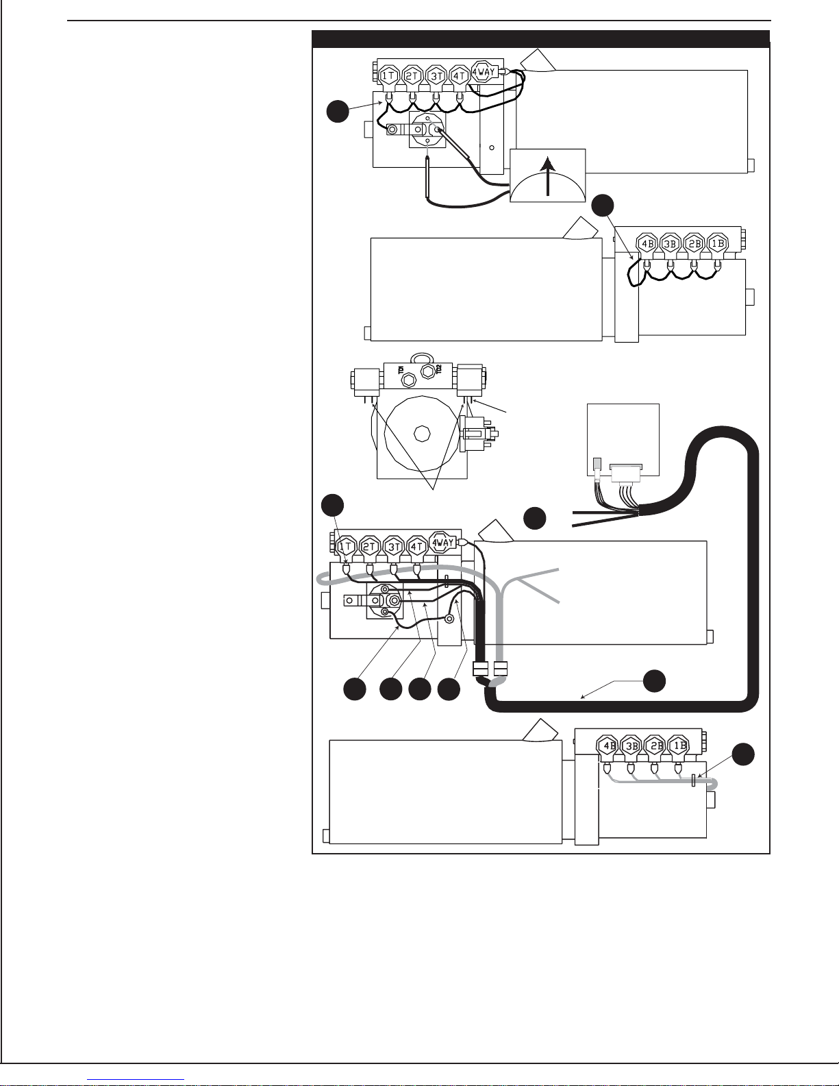
For Steps 2-6 Refer to Figure 2.
2. Install the daisy chain harness. This
harness is identified by its red color,
nine spade connectors and one ring
terminal.
2a. Attach the ring terminal to the
bolt on the motor side of the
solenoid. Then attach the spade
connectors to the inside spade on
the valve solenoids working your
way around the manifold from 1T
through 4T.
2b. Attach the next spade
connector to the 4-way valve
solenoid and pass the remaining
section of the daisy chain across to
the 4B valve solenoid. Attach the
spade connector to 4B through 1B.
3. Attach the wiring harness pigtail to
the pump by attaching the wires
corresponding to the valve markings
on the top of the manifold. Wire TD1
will not be connected at this time.
Wire TD2 is not used at all for this
installation so it can be coiled, tie
wrapped and secured at this time.
FIGURE 2
2a
3
Inside Male Spade
4.3
Outside
Male
Spade
6
14
2b
Back of
Control Unit
PKBK
IGN
TD 1 to Jack leg
position switches
TD 2
3a. Connect the black wire with the
ring lug to the ground bolt on the
side of the pump. On some pumps
this ground lug will be on the back of
the motor and have the black battery
cable connected to it.
3b. Connect the red wire with the
ring lug to the pump solenoid on the
battery cable side of the solenoid.
3c. Connect the white wire labeled
SOL + to one of the empty small
posts on the pump solenoid.
4. Connect the 12" jumper wire
included in the kit between the
remaining small posts on the
solenoid and the ground bolt on the
side of the pump.
5. Install the 16' multi-wire harness.
Route the end with the two
connectors that mate to the control
panel through the firewall and into
the dash area near the control panel
location.
4
6. At the small connector of the multi
wire harness that goes to the
control panel, are yellow, blue and
black wires. The black wire is not
used. Connect the yellow wire to an
ignition source that has 12 volts
when the engine is running.
Connect the blue wire to the park
brake wire. This connection must
show ground when the park brake
3b3c
3a
5
3
is set. In the chassis wiring harness
you will need to identify the park
brake signal wire. The park brake
switch and signal wire will usually
be found on, or near, the park brake
pedal assembly. This wire will show
ground or 12-volts positive when
the park brake is applied, the type
of signal will vary from one type
chassis to another.
 Loading...