

kvm-tec electronic gmbh – 2523 Tattendorf – Josef Gisperg Platz 7 – Austria www.kvm-tec.com
Tel + Fax +43-2253 / 81912 – Mobil +43-650 81912 02 – Email office@kvm-tec.com
Smartline KVM Extender – Quick Guide
SVX1 Packaging contents
1x SVX1 / PC
1x SVX1 / monitor
2x wall power supply
2x DVI-HDMI cable
1x USB cable
1x Quick Guide
4 mounting pads
4 rubber feet
Installation:
Connect the respective ports of your PC as shown below:
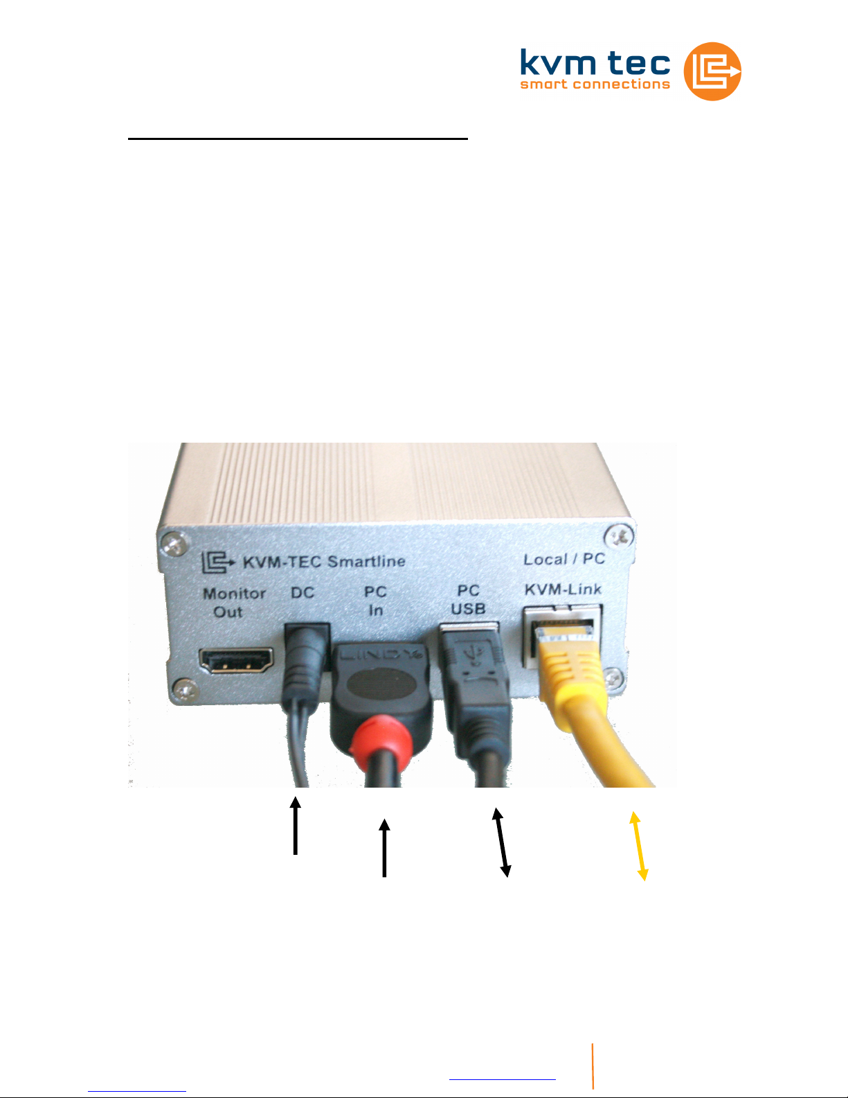
SVX1/PC:
From the AC
Adapter
From the DVI
output of the
To the
computer
USB port
Cat5 cable to
the monitor
part of the
Extender (up
to 100m)
kvm-tec electronic gmbh – 2523 Tattendorf – Josef Gisperg Platz 7 – Austria www.kvm-tec.com
Tel + Fax +43-2253 / 81912 – Mobil +43-650 81912 02 – Email office@kvm-tec.com
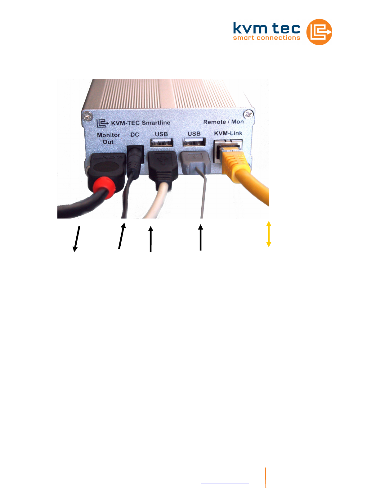
SVX1/Monitor
Operation:
Switch all devices on.
In the first 5 seconds the units executes a cable adjustment, which is indicated by a slow
flashing red LED. Once the status changes to green, all signals are transmitted.
Settings:
There are no adjustments necessary, the unit works by "plug and play".
The DVI input
of the monitor
From the AC
adapter
Keyboard
Mouse
Cat5 cable to
the PC part of
the Extender
(up to 100m)

kvm-tec electronic gmbh – 2523 Tattendorf – Josef Gisperg Platz 7 – Austria www.kvm-tec.com
Tel + Fax +43-2253 / 81912 – Mobil +43-650 81912 02 – Email office@kvm-tec.com
Installation SVX2:
The Smart Line SVX2 dual Extender installed just like SVX1.
The SVX2 consists of 2 independent extenders. This creates additional flexibility in the
application, as this provides 2 independent USB connections, even from different PCs.
Here, the power supply on the left or right side is connected. The second DC port can be
used for redundant power supplies as port.
SVX2 Package Contents
1x SVX2 / PC
1x SVX2 / Monitor
2x wall power supply
4x DVI-HDMI cable
1x USB cable
1x Quick Guide
4 mounting pads
4 rubber feet
Requirements Cat5/6/7 cable:
The pins are connected 1:1
Note: the cable pairs need to be connected according to EIA/TIA-568A or EIA/TIA-568 B
Incorrect assignments can not be found with a simple cable tester.
The pins for the green pair are not next to each other! The cable must be at least the
Cat5 specification and be suitable for Gigabit transmission.
Applicable standards: Class D of ISO / IEC 11801:2002 and EN 50173-1:2002.
Connection acc. to EIA/TIA-568 B
Pin color
1 orange/white
2 orange
3 green/white
4 blue
5 blue/white
6 green
7 brown/white
8 brown
Mechanical Attachment:
Optimum flexibility and security is achieved by using a
3M Dual Lock ™ fastening tape Type Type SJ-4570th This can also be used as a lower
table side in the cabinet or for mounting in 19 "rack.
Shielded installation cable min. 24AWG
Screen continuously connected at both ends.
Shielded patch cable as connection to the unit
is allowed.
 Loading...