

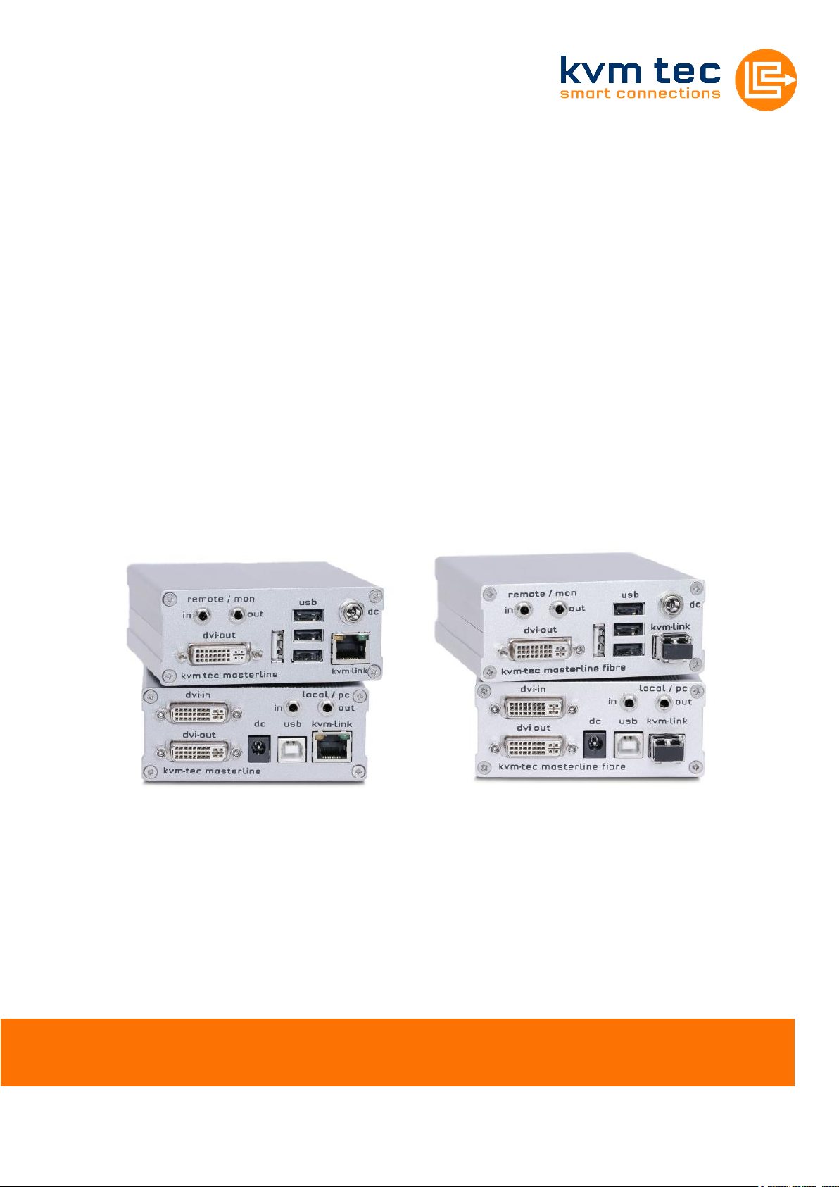
Manual
Masterline MVX/MVX-F KVM Extender
SWITCHING OPTION
Art.Nr: 6701
Masterline MVX1
Art.Nr: 6801
Masterline MVX1-F
www.kvm-tec.com

www.kvm-tec.com
Contents
Contents ....................................................................................................................................................... 2
1 Package contents .................................................................................................................................... 4
2 Specifications ........................................................................................................................................... 4
3 Installation ............................................................................................................................................... 4
4 Start up ..................................................................................................................................................... 6
4.1 Status Overview.................................................................................................................................................. 6
5 Menu / Settings ....................................................................................................................................... 8
5.1 Menu Item “U” – Update Flash FW .................................................................................................................... 8
5.2 Menu Item “M” – Option Overview ................................................................................................................... 8
5.3 Menu Item “O” – DDC Option ............................................................................................................................ 9
5.4 Menu Item “W” – Network Settings ................................................................................................................ 10
5.5 Menu Item “G” – Extender Settings ................................................................................................................. 10
5.5.1 Menu Item “V” – VGA parameters ........................................................................................................... 11
5.5.2 Menu Item “A” – Audio Input Gain .......................................................................................................... 12
5.5.3 Menu Item “R” – RS232 ............................................................................................................................ 12
5.5.4 Menu Item “S” – Show Last Image ........................................................................................................... 13
5.5.5 Menu Item “I” – Monitor Sync ................................................................................................................. 13
5.5.6 Menu Item “L” – Lock Menu ..................................................................................................................... 14
5.5.7 Menu Item “P” – Power Save ................................................................................................................... 14
5.5.8 Menu Item “K” – Keyboard Locale ........................................................................................................... 14
5.5.9 Menu Item “U” – USB Compatibility Mode .............................................................................................. 14
5.5.10 Menu Item “H” – Keyboard Shortcuts ................................................................................................ 15
5.6 Menu Item “L” – Switching List ........................................................................................................................ 15
5.7 Menu Item “Q” ................................................................................................................................................. 16
6 SWITCHING Menu Guide / Settings ................................................................................................... 17
6.1 Network Settings Item “V” – Master View (Device Configuration) .................................................................. 18
6.1.1 Master View Item “O” – Connections Overview ...................................................................................... 18
6.1.2 Master View Item “U” – User List ............................................................................................................. 19
6.1.3 Master View Item “C” – Console Extender List ........................................................................................ 21
6.1.4 Master View Item “P” – PC Extender List ................................................................................................. 22
6.1.5 Master View Item “M” – Multi-Head Configuration ................................................................................ 22
6.2 Network Settings Menu Item “M” – Network Mode ....................................................................................... 24
6.2.1 Network Settings Mode Item “R” – Reset Modes to Factory Default ...................................................... 24
6.2.2 Network Settings Mode Item “P” – Passwords Disabled ......................................................................... 24
6.2.3 Network Settings Mode Item “C” – Auto Connect ................................................................................... 25
2

www.kvm-tec.com
6.2.4 Network Settings Mode Item “V” – Private Connections ......................................................................... 25
6.2.5 Network Settings Mode Item “B” – User-PC Binding ............................................................................... 25
6.2.6 Network Settings Mode Item “D” – Disconnect on PC Power Down ....................................................... 26
6.2.7 Network Setting Mode Item „S“ - Video Sharing ..................................................................................... 26
6.3 Network Settings Item “T” – Set Timeout ........................................................................................................ 26
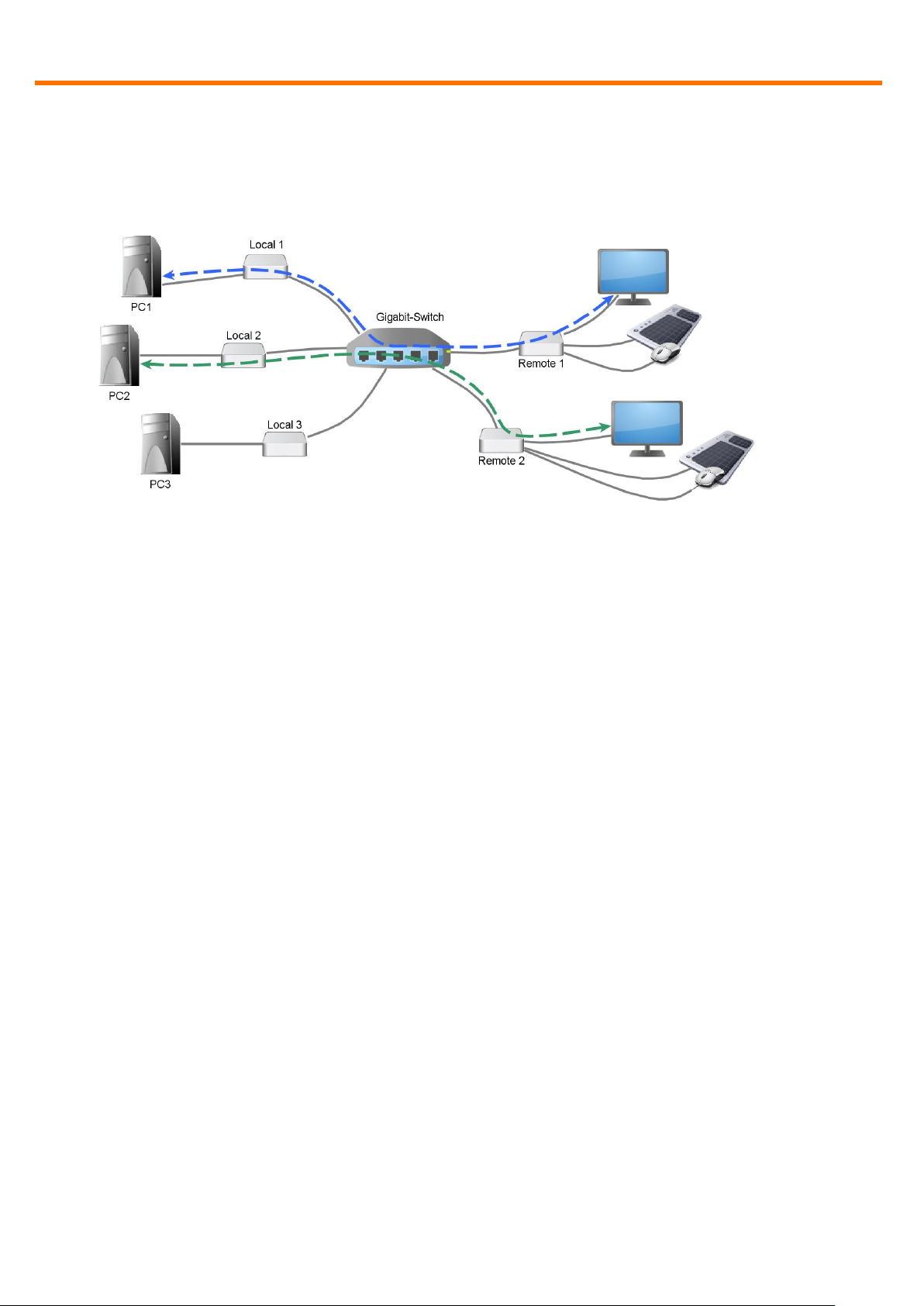
7 Switching between different computers .......................................................................................... 27
8 Multicast ................................................................................................................................................ 29
8.1 Video Sharing ................................................................................................................................................... 29
9 Mounting Options ................................................................................................................................ 30
9.1 Mounting Pads ................................................................................................................................................. 30
9.2 Rack Mounting Kit ............................................................................................................................................ 30
9.3 Under desk Mounting Kit ................................................................................................................................. 30
9.4 Din Rail Mounting Kit........................................................................................................................................ 30
9.5 Dual Mounting Kit ............................................................................................................................................ 30
10 Requirements ....................................................................................................................................... 31
11 Support ................................................................................................................................................. 32
12 Guidelines ............................................................................................................................................. 33
3
Package contents
www.kvm-tec.com
1 Package contents
1x MVX1 / PC 1x USB cable
1x MVX1 / Monitor 1x Quick Start Guide
2x Power supply 12V 1A 4x Mounting Pads
1x DVI-cable 4x Rubber Feet
2 Specifications
Max. ambient temperature: 45° Celsius
Dimensions: 98 x 41 x 106mm
Weight: 540g per Set
Power input: 5 W per device
Material: anodized aluminium
Power supply: 12V 1A external power supply
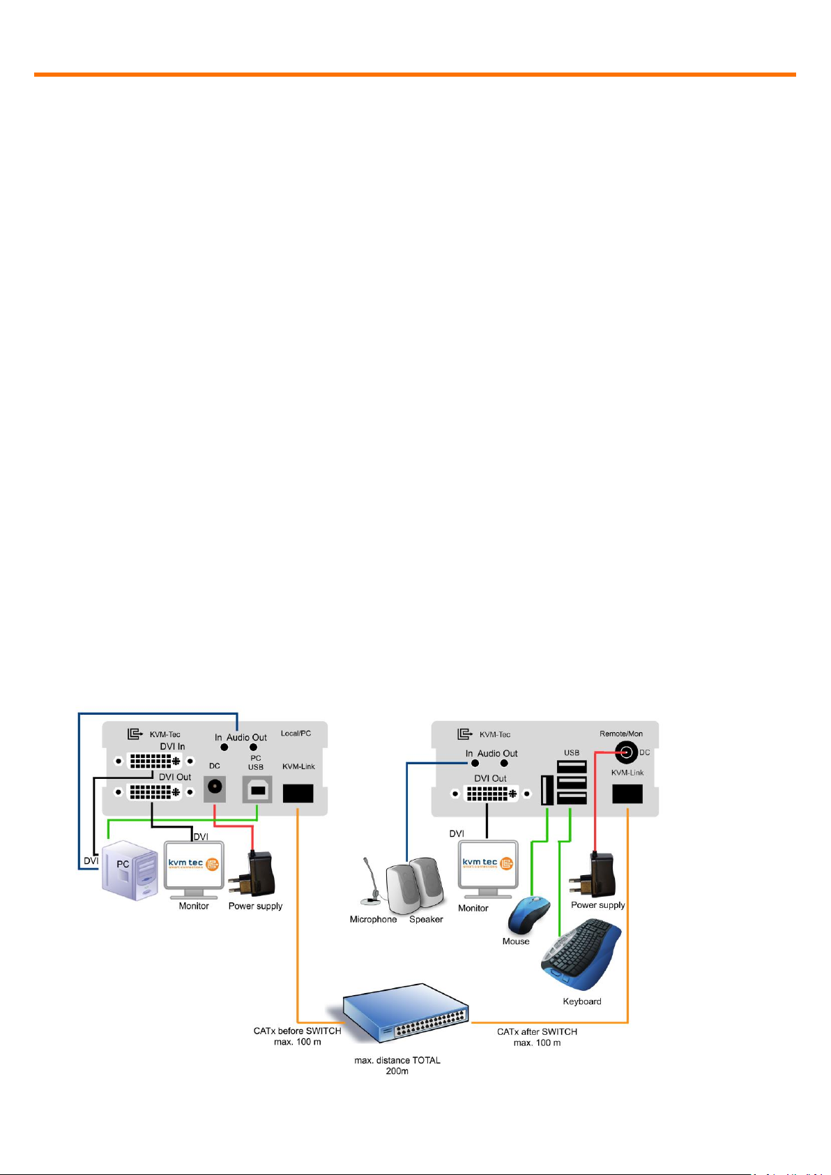
3 Installation
Connect all the cables from your PC as shown in the following diagram:
4
Installation
www.kvm-tec.com
Connect the respective work stations (Remote Extenders) and computers (Local
Extenders) with the network switch.
Note the following:
The entire switching network system requires its own dedicated network. For
security reasons it cannot be integrated into an existing company network.
The network switch must fulfil the following specifications: 1 Gigabit Switch, with true
port to port transfer rates of 1 Gigabit/second
List of recommended network switches that have been tested with kvm-tec
extenders
TP-LINK TL-SG3216, 16port
TP-LINK TL-SG1016D, 16port
TP-LINK TLSG1048, 48port
DIGITUS DN80100,16port
LogiLink NS0050A, 5port
5
Start up
www.kvm-tec.com
Connected to <untitled>
DDC Opt remote monitor
Video Mode DVI
Resolution 1920x1080
USB Status High Speed
Options: Mem Switch
Rem FW Ver 4267
Local FW Ver 4267
[Link] [Conn] [Video] [USB]
Fig. 1
4 Start up
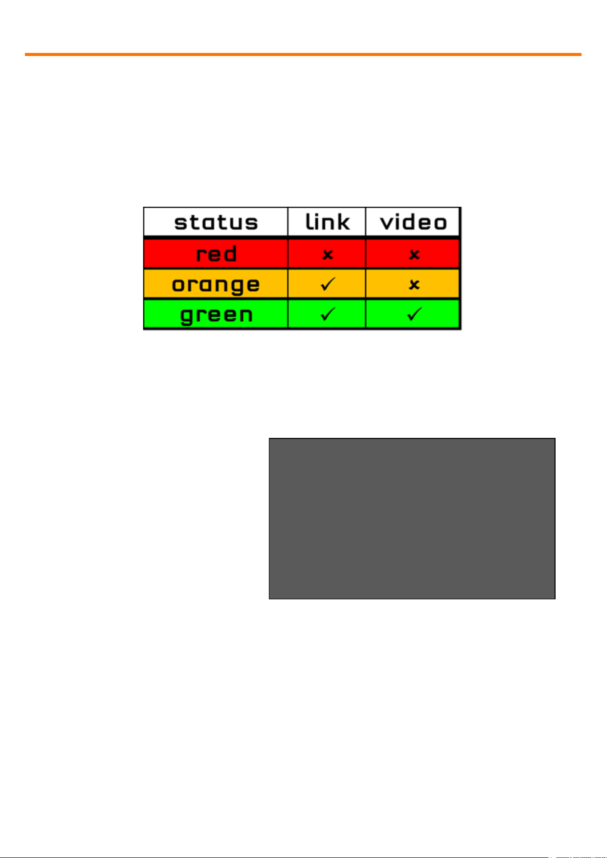
Switch on all devices. Both Extender units will start an automated initialisation
process, signified by a blinking red status light, this may take a few seconds.
When the status light turns green, all signals will be transmitted.
4.1 Status Overview
The Status Overview (Fig. 1)
provides the user with the most
important information about the
status of the extender in a single
screen. This will appear
automatically whenever no video
is been transmitted, but can also
be opened manually via the OSD
menu (see item 0). Of particular
interest is the row at the bottom,
showing the status of four subsystems as being either active (green) or inactive
(red).
6

www.kvm-tec.com
Link: Is there a physical link between this extender and another device via CATx
or fibre.
Conn: Has this console unit negotiated a connection with a PC unit.
Video: Is video currently being transmitted from the PC unit to the console unit.
USB: Has a transparent USB connection been established between the console
extender unit and the host PC.
7

Menu / Settings
www.kvm-tec.com
Menu
T = Status Overview
U = Update Flash FW
M = Option Overview
O = DDC Option (remote monitor)
W = Network Settings
G = Extender Settings
L = Switching List
Q = Exit
Remote (Con) FW Ver = 4267
Local (PC) FW Ver = 4267
Fig. 2
5 Menu / Settings
To enter the menu, use a keyboard connected to the remote Extender and press
the “<Scroll Lock>” key five times in quick succession.
The menu will be displayed (Fig. 2). Sub-menus are accessed by pressing the
appropriate key. The currently installed firmware version is displayed below the
menu.
5.1 Menu Item “U” – Update Flash FW
Used to perform a firmware update. The latest version of the firmware can be
downloaded from www.kvm-tec.com. Each update file is accompanied by a
detailed description of the update process.
5.2 Menu Item “M” – Option Overview
Displays the extender’s activated options. The status is indicated by the colours
green (activated), and red (not activated).
If the memory option on the extender is activated this can be enable or disabled
at any point in this menu.
In order to active options complete the following steps:
8

Menu / Settings
www.kvm-tec.com
DDC Options
+--------------------------------------+
0 = remote monitor
1 = local monitor
2 = last DDC fixed
4 = FIX 1024x768
5 = FIX 1280x1024
6 = FIX 1680x1050
7 = FIX 1920x1080
8 = FIX 1920x1200
Options Overview
[USB Memory] – Enabled
(1 – enable, 0 – disable)
[RS232] [VGA]
[Sound] [Switching]
Device ID: 123456f7
Send ID to distributor to unlock
options.
Press M to enter code.
Fig. 3
Fig. 4
The menu displays the ID number
of the device (see Fig. 3). Please
contact your distributor and
advice him of the ID number of
your device. They can then send
you the activation code for the
desired option. You can enter this
activation code by pressing the
“M” key. This will not alter other
options that have already been
activated. Return to the main
menu with “esc”.
5.3 Menu Item “O” – DDC Option
In this menu you can define DDC information is used by the PC .Pressing “0“
specifies that the DDC information from the monitor attached to the remote
Extender should be used. Pressing “1“ specifies that the DDC information from
the monitor attached to the local Extender should be used.
Pressing “2“ saves the current DDC information allowing the system to continue
on the same after the Extender has been restarted.
Using the keys “4“ through “8“ sets the system to use a predefined resolution
which is saved (Fig. 4).
To return to the main menu press “ESC“.
9

Menu / Settings
www.kvm-tec.com
Extender Settings
+--------------------------------------+
L = Local Settings
R = Remote Settings
Q = Return to Main Menu
Fig. 5
Local Settings
+--------------------------------------+
V = VGA parameters
U = USB Compatibility Mode (disabled)
Q = Return to Main Menu
Fig. 6
5.4 Menu Item “W” – Network Settings
The menu includes the preferences and settings for the switching option.
See item 7.
5.5 Menu Item “G” – Extender Settings
This menu presents a range of
further preferences. They are
divided in to two sub-menus
depending on whether the setting
is stored on the Local (PC) unit or
Remote (console) unit.
10

Menu / Settings
www.kvm-tec.com
Remote Settings
+--------------------------------------+
A = Audio Input Gain (5)
R = RS232 Baudrate (up to 9600)
S = Show Last Image (disabled)
I = Monitor Sync (disabled)
L = Lock Menu (disabled)
P = Power Save (enabled)
K = Keyboard Locale (EN)
O = Keyboard Fallback Mode (0)
H = Keyboard Shortcuts
Q = Return to Main Menu
Fig. 7
5.5.1 Menu Item “V” – VGA parameters
This is where VGA preferences can be set and optimised.
By pressing the “F1” and “F4” keys the display area can be moved up and down.
“F2” and “F3” shift the display area left and right.
By using the “F5” and “F6” keys the display area can be reduced or enlarged to fit
the display area of the monitor.
Press the “<space bar>” to change the rate of change of the above settings. By
repeatedly pressing the “space bar“ this is set back to 1.
Use the “M” button to switch the video mode between:
Auto – the mode is automatically detected and set by the Extender
DVI – only DVI input is detected
VGA – only VGA input is detected
For automatic adjustment and positioning of the image area, press “K”.
Press “I” to reset parameters to default values.
To save the settings and exit the menu press “S” – for an exit without saving
press “Q”.
11

Menu / Settings
www.kvm-tec.com
Fig. 9
Audio Input Gain (5)
0 = Off
1 – 9 = Amplification Level
Shift up F1 F4 down 0
Shift <- F2 F3 -> 0
Zoom out F5 F6 in 2200
Pixelfine - F7 F8 + 0
Space = 1/10 steps
M = Video Mode Auto
K = Automatic seek
I = Init VGA Table
S = Save – exit
Q = Quit – no save
Fig. 8
5.5.2 Menu Item “A” – Audio Input Gain
This menu sets the volume of the audio input on the remote extender
(microphone). Default value is “5” and can amplified up to “9” and reduced down
to “0”. At “0” the audio input on the remote extender is disabled.
5.5.3 Menu Item “R” – RS232
The following signals are transfered, the pin numbers refer to a 9-pin D-sub plug.
The remote interfaces are DTE.
Pin Funktion
3 Transmit Data
2 Recieve Data
4 DTR
12

Menu / Settings
www.kvm-tec.com
Baudrate:
Parity:
Stopbits:
4800
No
1
9600
Odd
2
19200
Even
38400
Mark
57600
Space
115200
230400
8 CTS
The baudrate can be set in the menu. There is a universal setting for baudrates
up to 9600 which transmits all different RS232 configurations transparently.
For higher baud rates the following settings are available via the menu:
5.5.4 Menu Item “S” – Show Last Image
When this is enabled the console extender will not show a black screen when it is
no longer connected to a PC extender. Instead it will keep the last image that it
received. To indicate that this image is no longer current the edges of the screen
will flash red.
5.5.5 Menu Item “I” – Monitor Sync
The monitor synchronization can be turned on and off. When enabled, the
refresh rate of the graphics card of the PC and that of the remote monitor are
adjusted to match one another. The advantage of this is to ensure that
transmission remains smooth when the screen content changes rapidly (e.g.
when using multimedia applications).
Not all monitors support this method so by default this option is disabled.
Should the monitor start to flicker then it does not support this feature and it
should be disabled again.
13

Menu / Settings
www.kvm-tec.com
Lock Menu 5 Min after
Power-On is disabled
Enter 1 for enable or
0 for disable:
Fig. 10
5.5.6 Menu Item “L” – Lock Menu
Here the extender menu can be locked. When enabled, access to the menu will
be locked 5 minutes after start up. This prevents unauthorized access to the
extender menu. The extender must be restarted to enter the main menu again
(turn the power supply off and on).
The menu is enabled or disabled from this screen by pressing “0“ or “1“
respectively (Fig. 10). To return to the main menu press “ESC“.
5.5.7 Menu Item “P” – Power Save
When in power saving mode the remote extender will turn off its video out when
it receives no video for more than a minute. This enables the monitor to enter
sleep mode if supported. To wake press any key on keyboard.
5.5.8 Menu Item “K” – Keyboard Locale
Select between keyboard layouts for navigating the OSD. Choices are French
(Azerty), English (Qwerty) and German (Qwertz).
5.5.9 Menu Item “U” – USB Compatibility Mode
14

Menu / Settings
www.kvm-tec.com
KEYBOARD SHORTCUTS
+--------------------------------------+
> Main Menu 5x<scroll>
Switching List <L-Ctrl><L-Alt><F12>
Conn. Overview <L-Ctrl><L-Alt><F10>
Disconnect <L-Ctrl><L-Alt><F11>
Favourites <L-Ctrl><L-Alt><F1>
Use arrows to scroll up and down.
E = Edit
Q = Exit
The USB Compatibility Mode allows the local extender to go to the lowspeed
mode in some cases. One use case for activating this setting is when the PC has
problems initializing the keyboard in its BIOS. One reason for that could be that
the USB initialization in the PC's BIOS is buggy and can't correctly initialize
highspeed devices as it's the case in HP Z400 Series PCs. After activating, the
USB compatibility mode the local extender first tries to initialize in highspeed
mode and after it failed several times, enters lowspeed mode, which should solve
the problem. Under normal operation, this setting should remain deactivated.
5.5.10 Menu Item “H” – Keyboard Shortcuts
In this menu alternative keyboard shortcuts can be defined. By default there is
only one shortcut to change, the opening of the OSD. Note that if you enter in a
new shortcut to open the OSD, the 5 x Scroll Lock will continue to function as
well.
If the Switching Option is enabled then further shortcuts can be defined to open
the Switching List, Disconnect the current connection, open the Connection
Overview and connect to a favourite extender.
A shortcut can either be a combination of modifier keys (i.e. Shift, Ctrl, Win and
Alt) with another key, for example Ctrl-Shift-Home, or it can be tapping a single
key multiple times, for example double tap Caps Lock.
5.6 Menu Item “L” – Switching List
Takes you to the switching list (see section 7).
15

Menu / Settings
www.kvm-tec.com
5.7 Menu Item “Q”
To close the extender menu press the “Q” key.
16

SWITCHING Menu Guide / Settings
www.kvm-tec.com
NETWORK SETTINGS
+--------------------------------------+
V = Master View (Device Configuration)
M = Network Mode
T = Set Timeout (Immediately)
Q = Save and Exit
Enter User/Password
+--------------------------------------+
> USER: admin-------
> PASSWORD: admin-------
ESC = Cancel
Fig. 11
Fig. 12
6 SWITCHING Menu Guide / Settings
By pressing “W” in the main menu of the OSD you can access the settings of the
Switching Option and configure your network.
Please note that this menu item is only active when the Switching Option has
been unlocked on the Remote Extender.
To unlock an Option see item 5.2.
In order to prevent unauthorised access to to the Network Settings this item is
protected by a user/password. Access is only allowed for users with
administrator rights.
The factory settings provide an administrator user with User: admin and
Password: admin.
17

SWITCHING Menu Guide / Settings
www.kvm-tec.com
MASTER VIEW connections overview
+--------------------------------------+
> SERVER 1 <--> CONSOLE 1
SERVER 2 <--> CONSOLE 2
SERVER 3 <--> CONSOLE 3
CONSOLE 4
I = Show Details
Q = Exit
MASTER VIEW menu
+--------------------------------------+
O = Connections Overview
U = User List
C = Console Extender List
P = PC Extender List
M = Multi-Head Configuration
R = Restart All Extenders
Q = Exit
Fig. 13
Fig. 14
6.1 Network Settings Item “V” – Master View (Device
Configuration)
The master view menu provides the administrator with the ability to view, add,
edit or remove user, console and computer information.
6.1.1 Master View Item “O” – Connections Overview
Provides an overview of the current connections as well as the free PCs and
consoles on the network.
You may break a connection remotely, or assign a PC a new console or vice
versa.
18

SWITCHING Menu Guide / Settings
www.kvm-tec.com
MASTER VIEW connections detail
+--------------------------------------+
> Computer: SERVER 1
Workstation: CONSOLE 1
User: <None>
D = Force Disconnect
E = Select PC for workstation
Q = Exit
MASTER VIEW user list
--USER-----------+---GROUPS---+-RIGHTS-+
> admin | 1,2,3,4,5..| admin
master | 1,2 | master
user | 1 | user
| |
| |
| |
| |
A = Add R = Remove
I = Info Q = Exit
Fig. 15
Fig. 16
6.1.2 Master View Item “U” – User List
With this menu item you may manage user details, rights and groups.
Press the “A” key to add a new user. Delete a user by pressing the “R” key.
Pressing “I” displays details about the user which may be edited.
19

SWITCHING Menu Guide / Settings
www.kvm-tec.com
MASTER VIEW user list
--USER-----------+---BOUND PC----------+
> admin | <None>
User1 | SERVER 1
User2 | SERVER 2
|
|
|
|
A = Add R = Remove
I = Info Q = Exit
Fig. 17
User: Assign each user a login name with max. 16 characters.
Full Name: For clarity the full name of a user may be entered. This name is
displayed when informing other users who interrupted their connection.
Password: Each user requires a password for the login. Max. 16 characters
Rights: There are three types of rights: USER, MASTER and ADMIN. By pressing
the “+” key the rights of the selected user can be changed.
The rights control access to the Network Settings menu (only ADMIN), and which
users may interrupt the connection of which other users.
Admin: May interrupt connections of Masters and Users. In the case that an
Admin interrupts the connection of another Admin, the interrupted Admin may
reclaim the original connection. Private connections can’t be interrupted.
Master: May interrupt connections of Users. In the case that a Master interrupts
the connection of another Master, the interrupted Master may reclaim the
original connection. Admins and private connections can’t be interrupted.
User: In the case that a User interrupts the connection of another User, the
interrupted User may reclaim the original connection. Admins, Masters and
private connections can’t be interrupted.
Groups: Each user can join up to 8 user groups. Each computer is defined as
belonging to one user group. By default all computers are in the same user
20

SWITCHING Menu Guide / Settings
www.kvm-tec.com
MASTER VIEW user detail
+--------------------------------------+
> USER: admin
FULL NAME: Administrator
PASSWORD: admin
RIGHTS: *** (admin)
GROUPS: 1,2,3,4,5,6,7,8
Bound PC: SERVER 1
A = Add R = Remove
I = Info Q = Exit
MASTER VIEW console extender list
--NAME------------------------+-STATUS-+
> Workstation1 | this
Workstation2 | in use
Workstation3 | free
|
|
|
R = Remove (Disconnected Only)
I = Info Q = Exit
Fig. 18
Fig. 19
group. This system makes it possible to allow or deny different users access to a
computer. The user’s group access is set by pressing the buttons 1 – 8.
Bound PC: When in User-PC Binding mode (see 6.2.5) each user must have a PC
bound to them. That user will only be able to connect to that PC. When selected
the User Detail menu, press “RETURN” a list of PCs on the network will be
displayed to select from.
6.1.3 Master View Item “C” – Console Extender List
In the console list you may view all console extenders (remote extenders) in the
switching network and their current status.
“this” defines the extender which
you are currently using.
“in use” indicates that the
extender is in use.
“free” indicates that this extender
is not busy.
Each console extender (remote
extender) can be assigned a
name. Press the “I” key to bring up
the submenu.
21

SWITCHING Menu Guide / Settings
www.kvm-tec.com
MASTER VIEW PC extender list
--NAME----------------+-GROUP-+-STATUS-+
> SERVER1 | 1 | conn’d
| |
| |
| |
| |
| |
| |
R = Remove (Disconnected Only)
I = Info Q = Exit
Fig. 20
6.1.4 Master View Item “P” – PC Extender List
In the computer list you may view all the PC extenders (local extenders) in the
switching network, their group and current status.
Again, you can change the details like extender name and user group in the
submenu by pressing the “I".
6.1.5 Master View Item “M” – Multi-Head Configuration
If you use multiple monitors with a PC then you can group individual local and
remote extenders together with the Multi-Head settings, making them switch as
a single unit.
In order to simplify the following steps it is recommended that you first name
every extender by way of the menu items PC Extender List and Console Extender
List. To help identify the extenders, when in these menus, the selected extender
will start blinking red-green.
It is recommended that before performing the final installation that you first
bring all the extenders to a single location, connect them all to a single switch
and configure the network.
This configuration setup requires a monitor, a keyboard and a network switch.
22

SWITCHING Menu Guide / Settings
www.kvm-tec.com
MASTER VIEW multi-head detail
+--------------------------------------+
> Name: mhs1
Type: Undefined
Heads: 0
--Module List-------------------------- SERVER 1/1 | conn’d
SERVER 1/2 | in use
SERVER 1/3 | in use
A = Add Module E = Edit
Q = Exit and Save
MASTER VIEW multi-head configuration
--MULTI-HEAD SET-----+---TYPE---+-SIZE-+
> MULTIHEAD_SERVER | PC | 3
DUALHEAD_CONSOLE | Console | 2
DUAHLHEAD_SERVER | PC | 2
MULTIHEAD_CONSOLE | Console | 3
| |
| |
| |
A = Add R = Remove
I = Info Q = Exit
Fig. 21
Fig. 22
Bring up the Multi-Head menu and create a new Multi-Head set by pressing <A>.
The Detail menu will open in which you can give the Multi-Head Set a name.
In this menu you can add individual extenders to the set by pressing <A>. The
extender type is automatically determined once the first extender has been
selected. By pressing <R> you can remove an extender from the Multi-Head set.
Leave this menu and save by pressing <Q>.
Highly recommended:
In order to ensure that USB is always available, ensure that the first
extender in every multi-head set is the one with USB connectivity.
When you select a Multi-Head set in the main Multi-Head menu you can bring up
the details again to read or edit by pressing the <I> key.
23

SWITCHING Menu Guide / Settings
www.kvm-tec.com
NETWORK MODES
+--------------------------------------+
P = Passwords ............... [Enabled ]
C = Auto Connect ............ [Disabled]
V = Private Connections ..... [Disabled]
B = User-PC Binding ......... [Disabled]
D = Discon on PC Power Down . [Disabled]
H = Hide Info Display ....... [Disabled]
T = Reconnect on Startup .... [Disabled]
S = Video Sharing ........... [Disabled]
Q = Exit
Fig. 23
You may remove a dismantled or altered Multi-Head set from the system by
selecting it in the menu and pressing <R>.
6.2 Network Settings Menu Item “M” – Network Mode
The network modes allow you define just how you want the network system to
operate. Each of the modes available may individually be activated or deactivated
by pressing the appropriate key. You may have more than one selected
depending on their function. Some modes require others, and others are
incompatible with each other, but the system will automatically recognise this for
you.
6.2.1 Network Settings Mode Item “R” – Reset Modes to Factory
Default
This will reset the extenders to factory settings.
ATTENTION: All user/console/computer tables will be deleted.
6.2.2 Network Settings Mode Item “P” – Passwords Disabled
By turning on the password system - user groups and rights and login access will
be activated.
For more information about user groups and rights see item 6.1.2.
24

SWITCHING Menu Guide / Settings
www.kvm-tec.com
Access to the network settings is always protected by a login and password, even
when the password system is disabled.
6.2.3 Network Settings Mode Item “C” – Auto Connect
If your connection is interrupted by another user the switching system will
automatically connect you with a free computer when the Auto Connect setting
is active.
This function is unavailable while using the Password System.
6.2.4 Network Settings Mode Item “V” – Private Connections
By activating the private connection function, users can set up a private
connection with a computer, which can’t be interrupted by other users.
To establish a private connection hold down “<Shift>” while you select a new
connection (either in the switching menu or by pressing the hotkey combination).
See item 7 Switching.
6.2.5 Network Settings Mode Item “B” – User-PC Binding
When in the User-PC Binding mode the switching system behaves quite
differently. Each console start unconnected and displaying the log in screen (Fig.
11). The switching menu and switching hot keys are not available. The admin
must configure each user to have a specific PC bound to them (see 6.1.2). When
a user logs on they will be automatically connected to their bound PC. If another
user wishes to use the console the first user must disconnect and logout with
the key combination Ctrl-Alt-F11.
Users with Master or Admin rights are able to access the switching menu as
normal once they’ve entered their login details.
25

SWITCHING Menu Guide / Settings
www.kvm-tec.com
Password Timeout
See product manual
For explanation
> I – Immediately
N – Never
T – Time in mins
Press ESC to exit
Fig. 24
6.2.6 Network Settings Mode Item “D” – Disconnect on PC Power
Down
When enabled any local extender that is connected to a PC that is powered
down will automatically break its connection allowing the remote extender to
find a different local extender to connect to.
6.2.7 Network Setting Mode Item „S“ - Video Sharing
For further information, please see item 8.1
6.3 Network Settings Item “T” – Set Timeout
When the password system is activated you can define under what
circumstances the user will required to enter their login details when switching.
I – Immediately: User and password must be entered for each switch.
N – Never: User and password are not required until the current user
logs out. See item 7.
T – Time in min: You define the number of minutes since the last switch
before the user and password details are required again to
switchs.
26

Switching between different computers
www.kvm-tec.com
7 Switching between different computers
The menu for the switching option is accessed via a USB keyboard on the
Remote Extender. Press “Ctrl+Alt+F12” to display the switching menu (see Fig.
25).
The switching menu will list all the computers (Local Extenders) connected to the
switching network.
Blue indicates the computer with which you are currently connected. The status
is listed as “conn’d”.
White indicates a computer which is currently conntected to by another work
station (Remote Extender). The status is listed as “in use”.
Green indicates a computer in the switching network that isn’t connected to any
work station (Remote Extender). The status is listed as “free".
Red indicates a computer which was once in the switching network but isn’t
currently available. This usually indicates that the Extender has been
disconnected from the network. If this is the case the computer can be removed
from the switching menu with the “delete” key.
The list can be navigated by the “arrow up” and “arrow down” keys. The currently
selected computer is indicated by the greater than symbol on the left edge of the
OSD (On Screen Display). By pressing the “Return” key you will switch to the
selected computer.
The left column defines the favourites menu, and provides each computer with
a favourite number. Each favourite number corresponds to a hotkey
combination that can be used to quickly connect to the desired computer
without having to access the switching menu. For example favourite “1” has the
hotkey combination “Ctrl+Alt+F1”, for favourite “2” it’s “Ctrl+Alt+F2” and so on
up to favourite “8” with “+Alt+F8”. All other computers can still be accessed via
the switching menu.
27

Switching between different computers
www.kvm-tec.com
> 1| PC1 |conn’d
2| PC2 |in use
3| PC3 |free
4| PC4 |discon
| |
| |
| |
| |
| |
User: admin X – Logout
D – Disconnect
[Link] [Conn] [Video] [USB]
Fig. 25
If the password system is active, the user in currently logged in is displayed at
the bottom. You can manually logout by pressing the “x” key or disconnect from
the current PC by pressing the „d“ key.
28

Multicast
www.kvm-tec.com
8 Multicast
8.1 Video Sharing
When the Video Sharing Mode is enabled, users can share their screen with
other users on the network.
What happens with the control over the local extender depends on the initial
state.
There are two main use-cases which can both be controlled in the "MASTER
VIEW connections overview" menu - which can be reached with the key
combination Ctrl-Alt-F10.
1. A user needs his/her screen to be mirrored to other consoles:
This can be done by opening "MASTER VIEW connections overview" and
pressing "P" over the console that should display the user's screen.
In this case "P" stands for "push to screen". Such a command is only valid if
the console which initiates the mirroring is currently connected to a local
extender and has video.
2. A user needs to see the screen of other consoles on the network:
This is done by opening "MASTER VIEW connections overview" and pressing
"G" over the console that should display the user's screen.
The key "G" stands for "get screen". If the console extender from which this
command is executed currently has a partner, a disconnect is executed
before the video of the other local extender is displayed.
If the selected local extender currently isn't connected, a connection including
USB, etc. is established.
“D” disconect
For help press "Strg+H"
29

Mounting Options
www.kvm-tec.com
9 Mounting Options
9.1 Mounting Pads
Included. These can be used to hold the Extenders in place by preventing them
from sliding and falling.
9.2 Rack Mounting Kit
Our rack mounting kits are optional extras, available in three varieties and make
installation convenient.
Now available with a redundant power supply.
RMK-F Part No. 6130; RMK-FN Part No. 6131; RMK-FRN Part No. 6132
9.3 Under desk Mounting Kit
Optional (Part No. 6937)
9.4 Din Rail Mounting Kit
Optional (Part No. 6136)
9.5 Dual Mounting Kit
Optional (Part No. 6937)
30

Requirements
www.kvm-tec.com
Pin
Color
1
Orange/White
2
Orange
3
Green/White
4
Blue
5
Blue/White
6
Green
7
Brown/White
8
Brown
Shielded installation cable with min.
cross section of 24AWG throughout the
length, shield is continguous and
connected to both ends.
Shielded patch cable is allowed for
connection to the device.
10 Requirements
Requirements for Cat 5/6/7 cables:
The pins are connected 1:1
Caution: the cable pairs must be twisted to EIA/TIA-568A (rare) or EIA/TIA-568 B
(common) pairs!
Erroneous assignments can not be found with a simple cable tester.
The pins for the green pair of wires are not adjacent to one other! The cable
must at the very least meet the Cat5 specifications and be suitable for Gigabit
transmission.
Applicable standards: Class D ISO/IEC 11801:2002 or EN 50173-1:2002.
Schema EIA/TIA-568 B
Requirements fibre
Multi-Mode (standard)
Included with the MVX1-F is a LWL Multimode – SFP
Module which allows a transmission distance of up to
500m.
Requires dedicated fibre connection, cable type Duplex
Multimode 50/125μ (OM2), LC connector
Single-Mode (optional)
LWL Singlemode – SFP Module up to 20km transmission distance
Requires dedicated fibre connection, cable type Duplex Singlemode, LC
connector
LWL Singlemode – SFP Modul BiDi up to 20km transmission distance
Requires dedicated fibre connection, cable type Singlemode, LC connector
Wavelength ( ) 850nm in multimode
1310nm TX – 1550nm RX in singlemode
31

Support
www.kvm-tec.com
11 Support
If you have any questions about our products, please contact your dealer.
Kulturstraße 1
2522 Oberwaltersdorf, Austria
Tel / Fax: 0043 (0) 2253 81912
Email: office@kvm-tec.com
Web: www.kvm-tec.com
Find our latest updates and FAQs on our homepage: http://www.kvmtec.com/support
32

Guidelines
www.kvm-tec.com
12 Guidelines
KVM-TEC Electronic GmbH
Kulturstrasse 1, 2522 Oberwaltersdorf, Austria
Commercial register number: FN 272328h LG Wr. Neustadt
DOCUMENT OF CONFORMITY
CE KONFORMITÄTSERKLÄRUNG
I hereby declare that the device:
KVM-Extender Type/Model:
MVX Digital KVM Extender/PC and Digital KVM Extender/Mon
when used with a shielded CATx cable fulfils the requirements of EU Directive
2004/108/EC (EMV / EMC) “Electromagnetic Compatibility”
and the harmonized European standards listed within.
In particular, the limits of the following standards are observed:
Safety
EN 60950-1:2006+A2:2013, IEC 60950: 2005
LASER CLASS 1: EN 60825-1:2007 compatible with IEEE 803.3z
EMC / EMV
EN 55022: 2010 Class A
EN 55024: 2010
EN 61000-3-2 2014
EN 61000-3-3 2013
EU Directive
2006/95/EC low voltage directive
EMC directive 2004/108/EC EMV guideline
EU directive 2011/65//EU (RoHS II)
The device was tested in a typical application with a PC.
Oberwaltersdorf, November 2015
Dietmar Pfurtscheller
Geschäftsführer / CEO
Warning !
This is a Class A product. This product may cause radio interference in residential
areas. In this case adequate counter measures may be requested from the
operator.
33

www.kvm-tec.com
 Loading...