

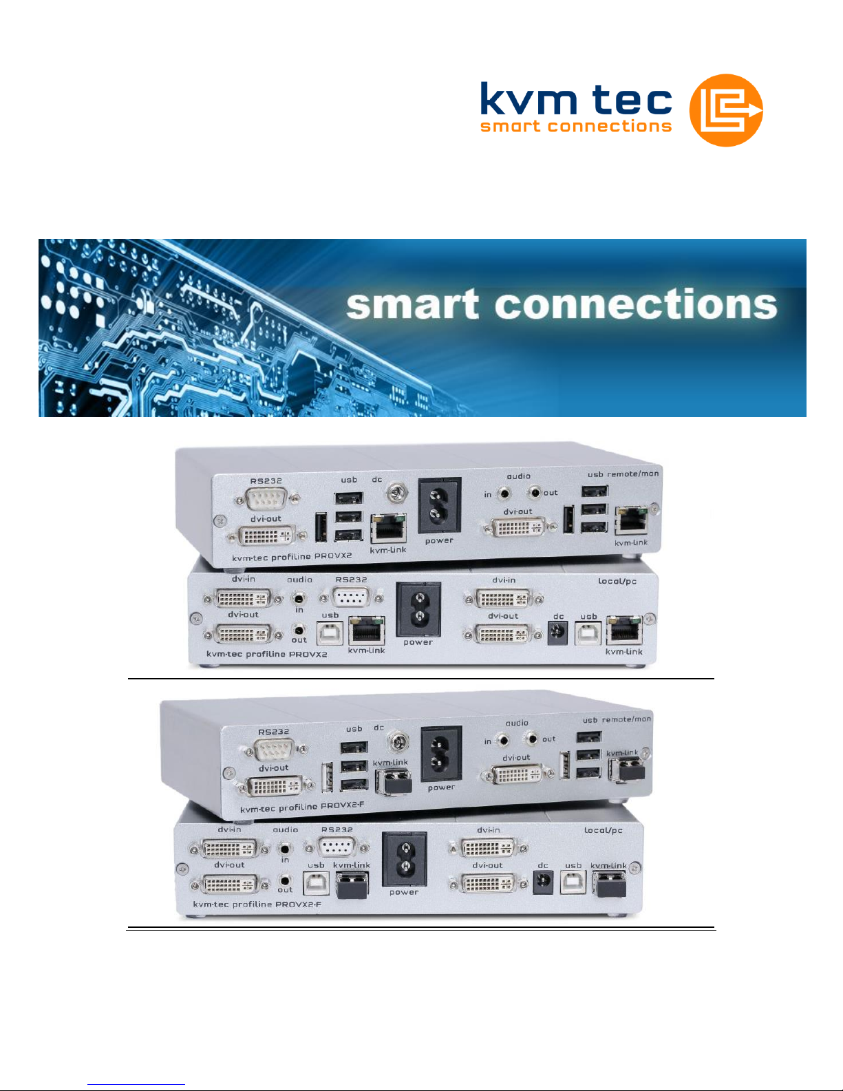
Profiline PROVX2/PROVX2-F KVM Extender
Instruction Manual
Part No. 6202
PROVX2
Part No. 6302
PROVX2-F
KVM-TEC PROVX2(-F) Ver. 1.1 Long
kvm-tec electronic gmbh – 2522 Oberwaltersdorf – Kulturstrasse 1 – Austria
Tel +43-2253 / 81912 – Fax +43 2253 819 12 99 – Email office@kvm-tec.com
- 2-
www.kvm-tec.com
1 PROVX1 Package contents
1x PROVX2(-F) / PC 1x USB/Audio cable
1x PROVX2(-F) / Monitor 1x Instruction manual
2x Power cable 2pol. 8x Rubber feet
2x DVI-cable 4x SFP Modul-Multimode (only by Fibre)
2 Specifications
Max. ambient temperatur: 45° Celsius
Dimensions: 220 x 45 x 130mm
Weight: 1547g per Set
Power input: 12W per device
Material: anodized aluminium
Power supply: internal 100-240V
Fibre model: Class 1 Laser Product 1 according to DIN 40008/EN and
VDE 0837
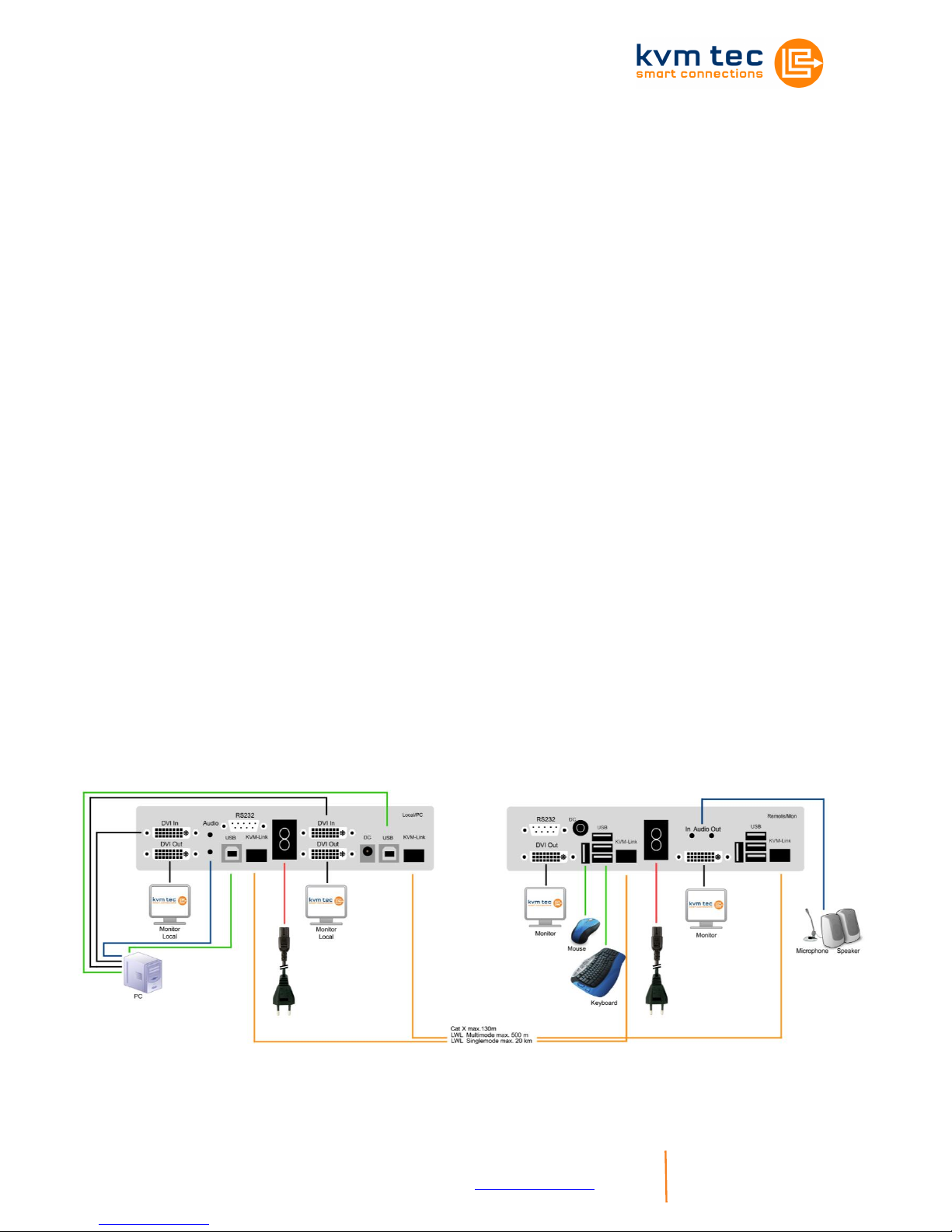
3 Installation
Connect all the cables from your PC as shown in the following diagram.
KVM-TEC PROVX2(-F) Ver. 1.1 Long
kvm-tec electronic gmbh – 2522 Oberwaltersdorf – Kulturstrasse 1 – Austria
Tel +43-2253 / 81912 – Fax +43 2253 819 12 99 – Email office@kvm-tec.com
- 3-
www.kvm-tec.com
3.1 Plug in/unplug the CATx cable
The Masterline MVX CATx Extender is delivered with an RJ45 socket.
Plug the CATx cable with the corresponding RJ45 plug (see section 7
requirements for CATx cable) into the RJ45 socket. Check that the plug is
latched in place to prevent faults.
To remove the CATx cable press the latch down and slowly pull the cable
out.
3.2 Plug in/unplug the LWL cable
Fibre model: Class 1 Laser Product 1 according to DIN 40008/EN and
VDE 0837
Attention: Avoid exposure to the beam!
The Masterline MVX Fibre Extender is delivered with a multimode SFP
module as standard. If a different SFP module is used, remove the black
dust protector from the SFP module and pull the metal latch of the module
forwards until it’s at a right angle, then the SFP module may be removed.
To plug in the new SFP module into the extender follow the same steps in
reverse.
To connect the fibre cable check that dust protector has been removed
and slot the fibre cable in until latch has clicked in to place. To remove the
fibre cable press on the latch and slowly remove the cable.
KVM-TEC PROVX2(-F) Ver. 1.1 Long
kvm-tec electronic gmbh – 2522 Oberwaltersdorf – Kulturstrasse 1 – Austria
Tel +43-2253 / 81912 – Fax +43 2253 819 12 99 – Email office@kvm-tec.com
- 4-
www.kvm-tec.com
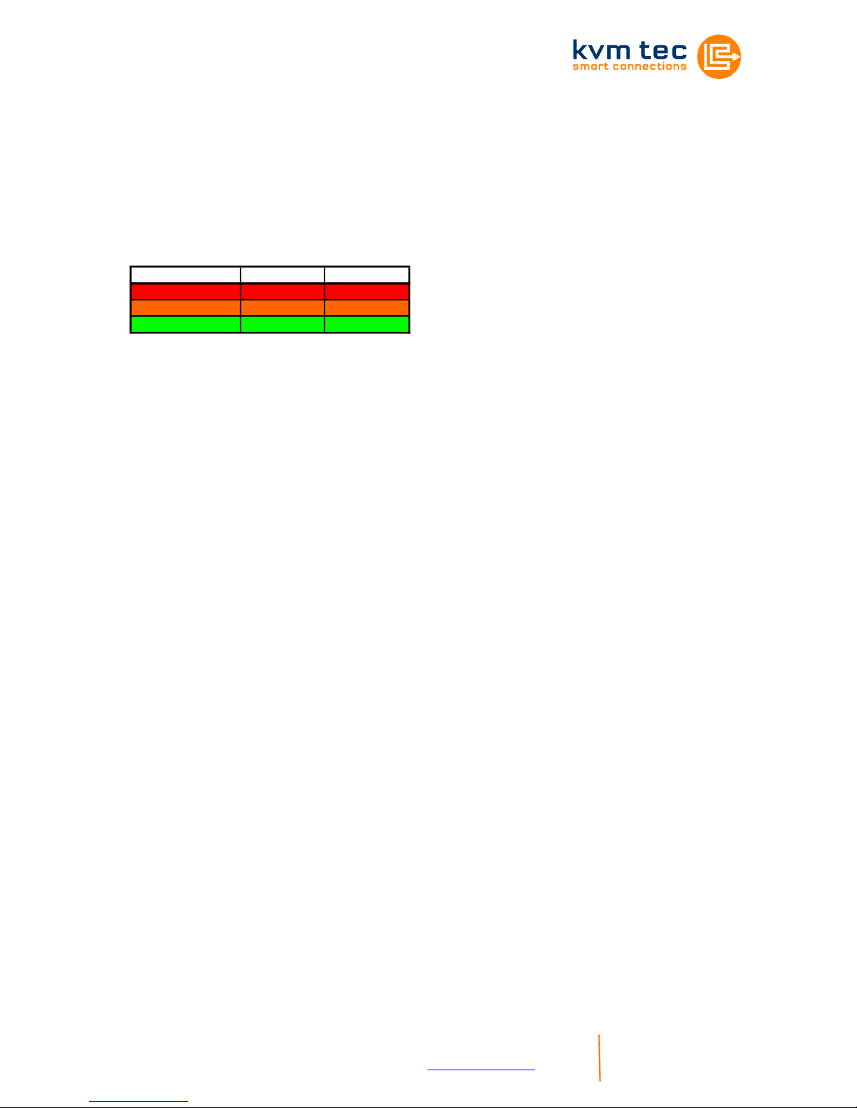
4 Start up
Switch on all devices. Both Extender units will start an automated
initialisation process, signified by a blinking red status light, this may take
a few seconds. When the status light turns green, all signals will be
transmitted.
SVX Status LED Verbindung Videosignal
rot
orange
grün
5 Mounting Options
5.1 Rackmounting Kit
Our rack mounting kits make installation convenient.
Optional (Part No. 6430)
5.2 Underdesk Mounting Kit
Optional (Part No. 6735)

KVM-TEC PROVX2(-F) Ver. 1.1 Long
kvm-tec electronic gmbh – 2522 Oberwaltersdorf – Kulturstrasse 1 – Austria
Tel +43-2253 / 81912 – Fax +43 2253 819 12 99 – Email office@kvm-tec.com
- 5-
www.kvm-tec.com
6 Menu / Settings
To enter the menu, use a keyboard connected to the remote Extender
and press the „Scroll Lock“ key five times in quick succession.
The menu will be displazed (Fig.1). Sub-menus are accessed by
pressing the appropriate key.The currently installed firmware version is
displayed below the menu.
6.1 Menu Item „U“
Used to perform a firmware update. The latest version of the firmware
can be downloaded from www.kvm-tec.com. Each update file is
accompanied by a detailed description of the update process.
Menu USB High Speed Mem
U = Update Flash FW
M = USB Memory Option
L = Lock Menu disabled
I = Monitor sync disabled
O = DDC Opt remote monitor
V = VGA parameter
Q = Exit
FW Version Rem=1178 Loc=1178

KVM-TEC PROVX2(-F) Ver. 1.1 Long
kvm-tec electronic gmbh – 2522 Oberwaltersdorf – Kulturstrasse 1 – Austria
Tel +43-2253 / 81912 – Fax +43 2253 819 12 99 – Email office@kvm-tec.com
- 6-
www.kvm-tec.com
6.2 Menu Item „M“
Allows the user to enable/disable
the memory option. When
activated USB flash storage and
external storage devices may be
used via the Extender.
If your Extender was provided with
this functionality you can turn it on
and off from this menu at any
time.
If the Extender didn't come with
this functionality, it can be upgraded by your dealer.
In this case, the menu displays the ID of the device (Fig. 2).
Consult your dealer and submit the ID of the device. They can send you
the appropriate unlock code.
After entering the correct code the Extender will restart and will display
“memory“ in the title of the main menu.To return to the main menu press
“ESC“.
6.3 Menu Item „L“
Here the Extender menu can be
locked. When enabled, access to
the menu will be locked 5 minutes
after start up. This prevents
unauthorized access to the
Extender menu. The Extender
must be restarted to enter the
main menu again (turn the power
supply off and on).
The menu is enabled or disabled
from this screen by pressing “0“ or
“1“ respectively(Fig. 3). To return to the main menu press “ESC“.
USB High Speed Memory Option
Enable: send ID to distributor
ID = 3fe687d5
Enter matching code
code = --------
Fig. 2
Fig. 3
Lock Menu 5 Min after
Power-On is disabled
Enter 1 for enable or
0 for disable:

KVM-TEC PROVX2(-F) Ver. 1.1 Long
kvm-tec electronic gmbh – 2522 Oberwaltersdorf – Kulturstrasse 1 – Austria
Tel +43-2253 / 81912 – Fax +43 2253 819 12 99 – Email office@kvm-tec.com
- 7-
www.kvm-tec.com
6.4 Menu Item „I“
The monitor synchronization can
be turned on and off. When
enabled, the refresh rate of the
graphics card of the PC and that
of the remote monitor are adjusted
to match one another. The
advantage of this is to ensure that
transmission remains smooth
when the screen content changes
rapidly (e.g. When using
multimedia applications).
Not all monitors support this method so by default this option is disabled.
To activate simply press the "1" key in this menu. Should the monitor
start to flicker, this option can be disabled again by pressing the “0“ key.
To return to the main menu press “ESC“.
6.5 Menu Item „O“
In this menu you can define DDC information is used by the
PC.Pressing “0“ specifies that the DDC information from the monitor
attached to the remote Extender should be used. Pressing “1“ specifies
that the DDC information from the monitor attached to the local Extender
should be used.
Pressing “2“ saves the currentDDC information allowing the system to
continue on the same after the Extender has been restarted.
Using the keys “4“ through “8“ sets the system to use a predefined
resolution which is saved (Fig. 5).
To return to the main menu press “ESC“.
Fig. 5
DDC Options (0)
0 = remote monitor
1 = local monitor
2 = fix actual DDC
4 = KVM-TEC fixed 1024x768
5 = KVM-TEC fixed 1280x1024
6 = KVM-TEC fixed 1680x1050
7 = KVM-TEC fixed 1920x1080
8 = KVM-TEC fixed 1920x1200
Monitor sync disabled
Enter 1 for enable or
0 for disable:
Fig. 4

KVM-TEC PROVX2(-F) Ver. 1.1 Long
kvm-tec electronic gmbh – 2522 Oberwaltersdorf – Kulturstrasse 1 – Austria
Tel +43-2253 / 81912 – Fax +43 2253 819 12 99 – Email office@kvm-tec.com
- 8-
www.kvm-tec.com
6.6 Menu Item „V“
This is where VGA preferences can be set and optimised.
By pressing the “F1“ and “F4“ keys the display area can be moved up
and down. “F2“ and “F3“ shift the display area left and right.
By using the “F5“ and “F6“ keys the display area can be reduced or
enlarged to fit the display area of the monitor.
Press the “space bar“ to change the rate of change of the above settings.
By repeatedly pressing the “space bar“ this is set back to 1.
Use the “M“ button to switch the video mode between “Auto“ – the mode
is automatically detected and set by the Extender, “DVI“ – only DVI input
is detected, and “VGA“ – only VGA input is detected.
For automatic adjustment and positioning of the image area, press “K“.
Press “I“ to reset parameters to default values.
To save the settings and exit the menu press “S“ – for an exit without
saving press “Q“.
Shift up F1 F4 down 0
Shift <- F2 F3 -> 0
Zoom out F5 F6 in 2200
Pixelfine - F7 F8 + 0
Space = 1/10 steps
M = Video Mode Auto
K = Automatic seek
I = Init VGA Table
S = Save – exit
Q = Quit – no save

KVM-TEC PROVX2(-F) Ver. 1.1 Long
kvm-tec electronic gmbh – 2522 Oberwaltersdorf – Kulturstrasse 1 – Austria
Tel +43-2253 / 81912 – Fax +43 2253 819 12 99 – Email office@kvm-tec.com
- 9-
www.kvm-tec.com
6.7 Menu Item „N“
This menu sets the volume of the audio input on the remote extender
(microphone). Default value is „5“ and can amplified up to „9“ and
reduced down to „0“. At „0“ the audio input on the remote extender is
disabled.
6.8 Menu item „Q“
To close the extender menu press the “Q“ key.
Audio Input Gain (5)
0 = Off
1 – 9 = Amplification Level
KVM-TEC PROVX2(-F) Ver. 1.1 Long
kvm-tec electronic gmbh – 2522 Oberwaltersdorf – Kulturstrasse 1 – Austria
Tel +43-2253 / 81912 – Fax +43 2253 819 12 99 – Email office@kvm-tec.com
- 10-
www.kvm-tec.com
7 Requirements
Requirements for Cat5/6/7 cables:
The pins are connected 1:1
Caution: the cable pairs must be twisted to EIA/TIA-568A (rare) or
EIA/TIA-568 B (common) pairs!
Erroneous assignments can not be found with a simple cable tester.
The pins for the green pair of wires are not adjacent to one other! The
cable must at the very least meet the Cat5 specifications and be suitable
for Gigabit transmission.
Applicable standards: Class D ISO/IEC 11801:2002 or EN 501731:2002.
Schema EIA/TIA-568 B
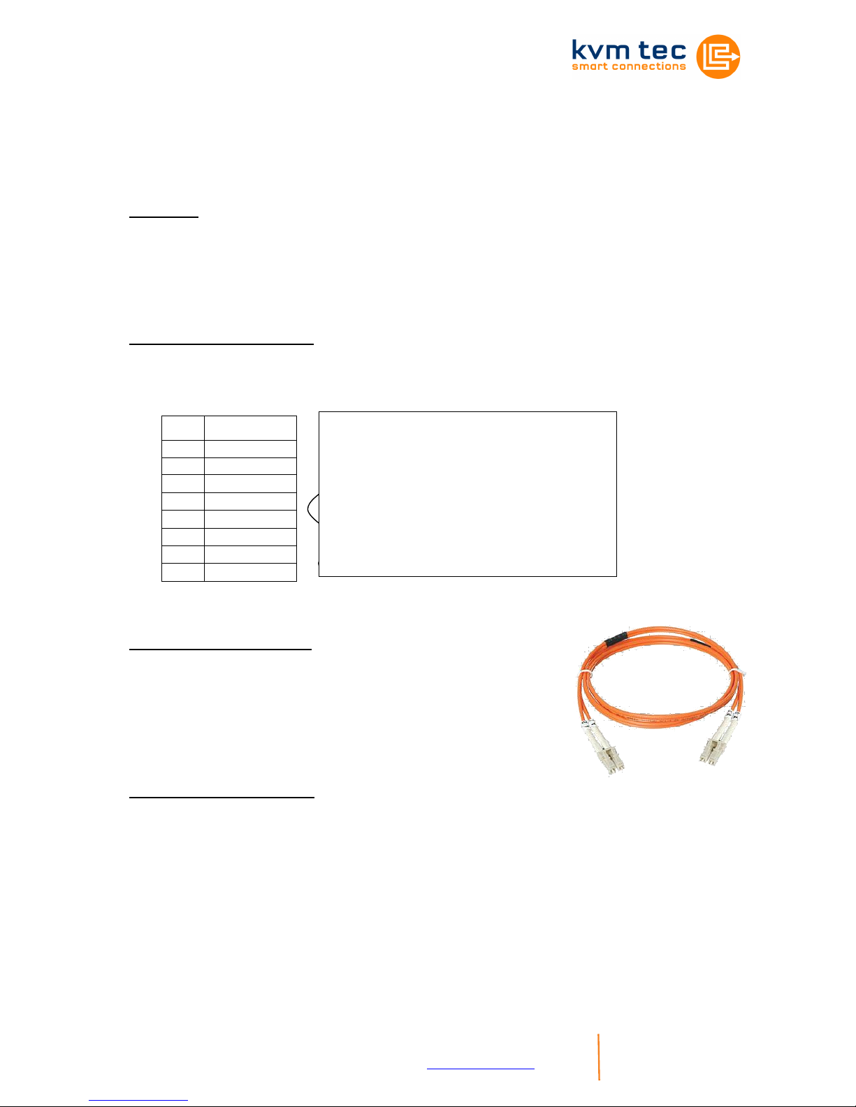
Requirements fibre
Multi-Mode (standard)
Included with the MVX1-F is a LWL Multimode –
SFP Module which allows a transmission distance
of up to 500m.
Requires dedicated fibre connection, cable type
Duplex Multimode 50/125μ (OM2), LC connector
Single-Mode (optional)
LWL Singlemode – SFP Module up to 20km transmission distance
Requires dedicated fibre connection, cable type Duplex Singlemode, LC
connector
LWL Singlemode – SFP Modul BiDi up to 20km transmission distance
Requires dedicated fibre connection, cable type Singlemode, LC
connector
Pin
Color
1
Orange/White
2
Orange
3
Green/White
4
Blue
5
Blue/White
6
Green
7
Brown/White
8
Brown
Shielded installation cable with min.
cross section of 24AWG throughout the
length, shield is continguous and
connected to both ends.
Shielded patch cable is allowed for
connection to the device.

KVM-TEC PROVX2(-F) Ver. 1.1 Long
kvm-tec electronic gmbh – 2522 Oberwaltersdorf – Kulturstrasse 1 – Austria
Tel +43-2253 / 81912 – Fax +43 2253 819 12 99 – Email office@kvm-tec.com
- 11-
www.kvm-tec.com
8 Guidelines
KVM-TEC Electronic GmbH
Kulturstrasse 1, 2522 Oberwaltersdorf, Austria
Commercial register number: FN 272328h Lg Wr. Neustadt
DOCUMENT OF CONFORMITY
CE KONFORMITÄTSERKLÄRUNG
I hereby declare that the device:
KVM-Extender Type/Modell:
PROVX Digital KVM Extender/PC und Digital KVM Extender/Mon
when used with a shielded CATx cable fulfils the requirements of EU
Directive 89/336/EWG „Electromagnetic Compatibility“ and the
harmonized European standards listed within.
In particular, the limits of the following standards are observed:
Safety
EN 60950 : 2001, IEC 60950 : 2001
EMC / EMV
EN 55022: 2006 Class A
EN 55024: 1999
EN 61000-3-2 2001
EN 61000-3-3 2002
EU Directive
2006/95/EC Low voltage directive
EMC Directive 89/336/EC EMV
The device was tested in a typical configuration with PC.
Tattendorf, 10. März 2010
Dietmar Pfurtscheller
Geschäftsführer / CEO
Warning !
This is a Class A product. This product may cause radio interference in
residential areas. In this case adequate counter measures may be
requested from the operator.

KVM-TEC PROVX2(-F) Ver. 1.1 Long
kvm-tec electronic gmbh – 2522 Oberwaltersdorf – Kulturstrasse 1 – Austria
Tel +43-2253 / 81912 – Fax +43 2253 819 12 99 – Email office@kvm-tec.com
- 12-
www.kvm-tec.com
9 Support
If you have any questions about our products, please contact your
dealer.
Kulturstraße 1
2522 Oberwaltersdorf
Tel / Fax: 0043 (0) 2253 81912
Email: office@kvm-tec.com
Web: www.kvm-tec.com
Find our newest updates and FAQs on our homepage:
http://www.kvm-tec.com/support
 Loading...