

KVM-TEC Matrixline 2000 Series, Matrixline MX2000-F, Matrixline MX2000 User Manual
USER-MANUAL
SMARTLINE SVX1
Matrixline 2000
IP
KVM Extender over
www.kvm-tec.com
MATRIXLINE MX
6711L CPU/LOCAL
6711R CON/REMOTE
MASTERLINE MVX1/MVX1-F KVM EXTENDER
Check out our
Installation Channel:
MATRIXLINE FIBER MX-F
6811L CPU/LOCAL
6811R CON/REMOTE

TABLE OF CONTENT
TABLE OF CONTENTS
1. introduction 6
1.1 Intended Use 6
1.2 Safety Instructions 7
1.3 Technical Specications 9
1.4 Product elements 10
1.5 Meaning of LED indicators 12
2. Installation of the Extender 13
2.1 Unpacking and checking the contents 13
2.2 Mounting options 14
2.2.1 Mounting pads and rubber feet 14
3. Extender SETTINGS 22
3.1 How to access the main menu 22
2 | kvm-tec
2.2.2 Mounting kits (optional) 14
2.3 Installing the extender 15
2.4 Startup 20
2.5 Replacing the SFP module 20
2.6 Removing a CATx cable 21
2.7 Removing a ber cable 21
3.1 How to access the main menu 22
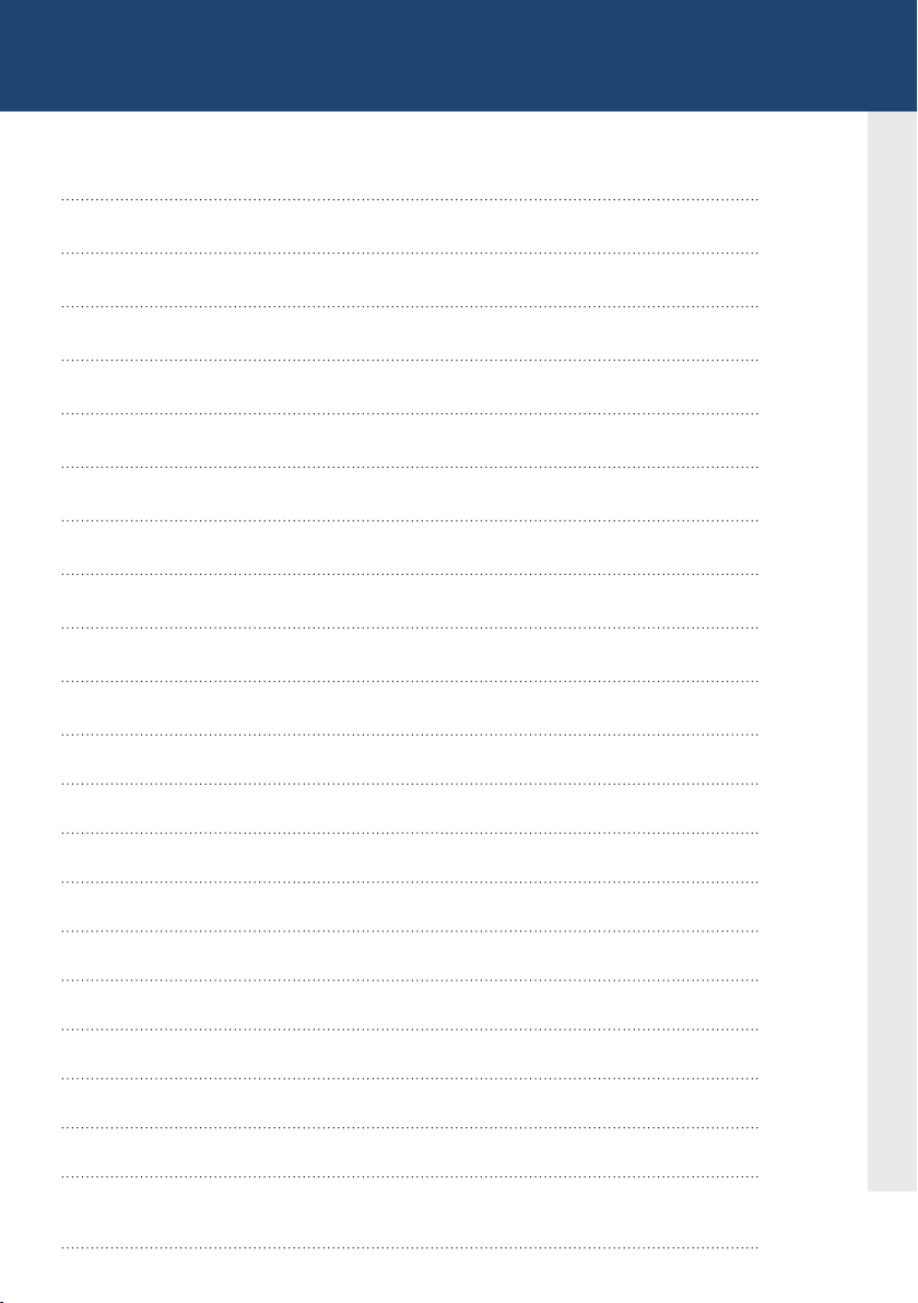
TABLE OF CONTENT
3.2 Status Menu 23
3.3 Display rmware version 23
3.4 Performing a rmware update 24
3.5 DDC Menü 25
3.6 Display unit list 26
3.7 Favorite list 27
3.8 Share list 28
3.9 How to change the extender settings 29
3.9.1 Changing local settings 30
3.9.2 Changing Remote settings 30
3.9.3 how to optimize vga preferences 31
3.9.4 How to set the audio volume 32
3.9.5 Congure a baud rate for the serial RS232 connection 33
3.9.6 Show the last received image 35
3.9.7. How to use the power saving mode 36
3.9.8. How to select your type of keyboard 37
3.9.9 How to change keyboard fallback mode 38
3.9.9 Keyboard Fallback Modus wechseln
3.9.10 How to change keyboard shortcuts 39
3.9.11 Close extender menu 39
3.9.12 Hide display status screen
40
kvm-tec | 3

TABLE OF CONTENT
3.10 How to switch betwee different computers 41
3.11 Video sharing 41
4. Network settings 43
4.1 Network settings and Management Switching Systems 43
4.2 Connecting,disconnecting or select a current workplace
connected devices 43
5. Maintance and care 44
6. Troubleshooting 44
7. Disposal 45
8. Warranty 46
9. Support 46
10. Declaration of conformity 47
11. Cable requirements 49
4 | kvm-tec
11.1 Requirements for CAT5e/6/7 cables 49
11.2 Requirements ber cables 50
11.2.1 Multi-Mode (standard) 50
11.2.2 Single-Mode (optional) 50
12 Requirements network switch 50

TABLE OF CONTENT
13. First aid 52
14. Extended warranty 53
15. Notes 54
kvm-tec | 5

1. INTRODUCTION
Congratulations on the purchase of your new Masterline MX/MX-F KVM Extender. You
have bought a high quality extender. These instructions are part of this product. They
contain important information regarding safety, use and disposal for every user of the
Matrixline MX2000 and MX2000-F KVM Extender. Please familiarise yourself with the
information within prior to using your product. Use the product only in the manner as
described and for the areas of application as stated. When passing the product to a third
party be sure to also supply all instructions and other relevant documentation. Following
proper use and maintenance, your Matrixline MX2000/MX2000-F KVM Extender will bring
you joy for many years to come.
1.1 INTENDED USE
This product is intended to be used as a device to increase the distance that a keyboard,
monitor and mouse can be placed from a computer. This product is intended for professional
use. The product should not be used in potentially explosive environments.
The product may only be used according to the instructions as described in this manual. All
use, other than that described in this manual, is seen as unintended use. Modications in the
course of technological progress are reserved. In these user instructions the Matrixline
MX/MX-F KVM Extender is referred to as ‘product’ or ‘extender‘. The MX/PC is referred to as the
‘local unit’ and the MX/Monitor is referred to as the ‘remote unit‘.
6 | kvm-tec

1. introduction
1.2 SAFETY INSTRUCTIONS
WARNING! Read and understand all safety instructions.
• Follow all the instructions. This will avoid accidents, re, explosions, electric shocks or
other hazards that may result in damage to property and/or severe or fatal injuries.
Please ensure that everyone who uses the product has read and followed these warnings
and instructions.
• Keep all safety information and instructions for future reference and pass them on to
subsequent users of the product.
• The manufacturer is not liable for cases of material damage or personal injury caused
by incorrect handling or non-compliance with the safety instructions. In such cases, the
warranty will be voided.
• This product is not intended for use by persons (including children) with restricted
physical, sensory or intellectual capability or lack of experience and/or knowledge, unless
they are supervised by a person who is responsible for their safety or provides them with
instructions on how to use the product.
• DANGER! Not for use in potentially explosive environments.
• DANGER! Be vigilant at all times, and always take care around this product. Do not use
electrical equipment if you are lacking in concentration or awareness, or are under the
inuence of drugs, alcohol or medication. Even a moment of inattentiveness can lead to
serious accidents and injuries when using electrical equipment. Check the product and
the cables for any damage before use. If there is any visible damage, a strong odour, or
excessive overheating of components unplug all the connections immediately and stop
using the product.
• DANGER! The MX-F KVM Extender is a Class 1 Laser Product 1 according to
DIN 40008/EN and VDE 0837.
• If the product is not installed and used in accordance with this manual, it may cause
disruptive interference with radio or television reception or affect other electronic
products in residential areas.
• Use shielded cables only to connect the components in order to avoid such interference.
Non-compliance invalidates the permission to operate this product.
• Only the mains adapter included with the product should be used as the power supply.
Do not use other adapters.
• Prior to connecting to the mains, make sure your local mains voltage matches the rating
indicated on the product.
• The product must be connected to a permanent and earthed AC wall socket.
1
kvm-tec | 7

1. introduction
• Protect cables from being strained, pinched or buckled and place them in a way to
prevent people from tripping over the cord.
• In particular, ensure to avoid damage to the mains adapter.
• Use the product with a suitable, properly installed and easily accessible mains power
socket. Make sure the product can be disconnected from the power socket at all times.
• Unplug the product during electrical storms or when not in use.
• DANGER! Never touch the adapter with wet hands.
• Use the product within the specied performance limits.
• Keep the product away from ammable materials such as curtains and drapes.
• Protect the mains adapter from use by third parties (particularly children). Keep the
unused mains adapter in a dry, elevated or locked location away from children.
• Do not place the product near heaters.
• Do not drop or hit the product.
• Unplug all connections before cleaning the product. Do not use wipes or chemicals
as these could damage the surface. Wipe the housing with a damp cloth. Electrical/
electronic parts must not be cleaned.
• Alterations to the product and technical modications are not permitted.
8 | kvm-tec

1. introduction
1.3 TECHNICAL SPECIFICATIONS
Type: KVM Extender (local unit and remote unit)
Model: Matrixline MX2000 und Matrixline 2000 Fiber MX-F KVM
Extender
Power supply input voltage: 100 - 240 V; 50/60 Hz AC
Power supply output: 12V; 1A (external power supply)
Power requirement: 6W per extender (excluding attached USB devices)
Operating temperature range: 0 ºC to 45 ºC / 32 °F to 113 °F
Storage temperature range: −25 ºC to 80 ºC / −13 °F to 176 °F
Relative humidity: max. 80% (non-condensing)
1
Storage humidity: max. 80% (non-condensing)
Casing Material: Anodized aluminium
Dimensions: approx. 97,5 x 41 x 103,5 mm / 3.83x 1.57 x 4.7 inch ”
Weight: local unit 302g/0.66lbs.
remote 291g/0.64lbs
Expected product life: 82 820 hours / 9.5 years
Laser MVX1-F: Class 1 Laser Product 1 according to DIN 40008/EN and
VDE 0837
kvm-tec | 9
1. introduction
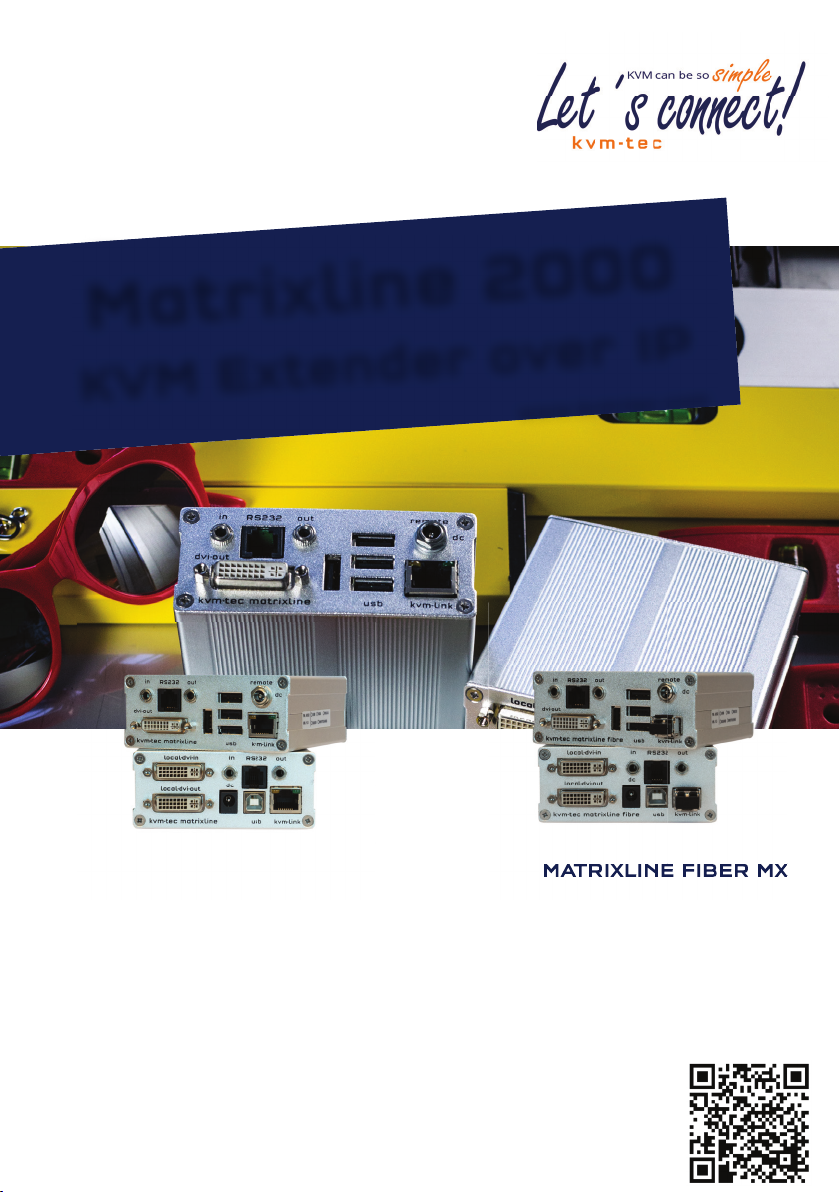
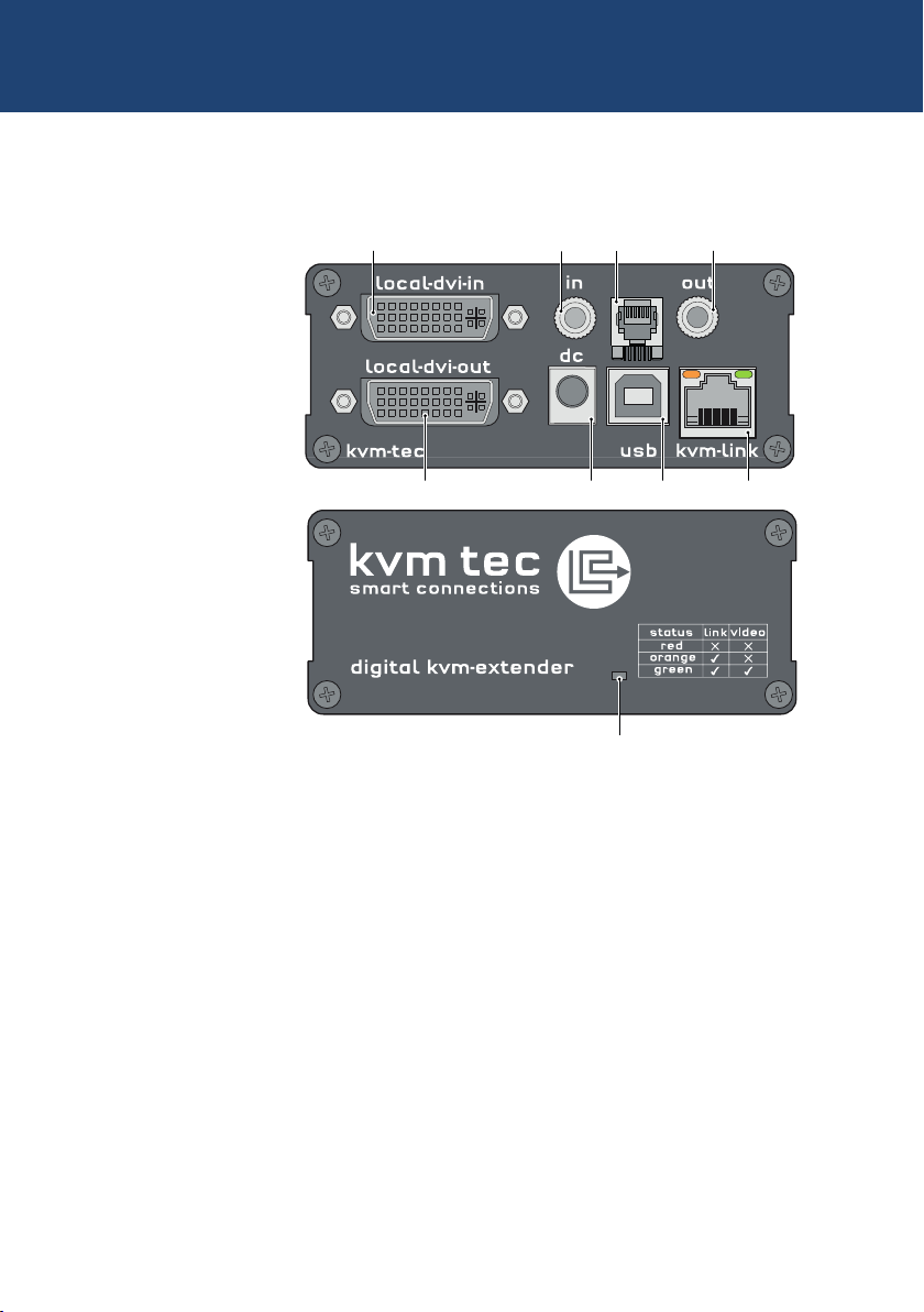
1.4 PRODUCT ELEMENTS
Local Extender (CPU)
Nr. Name Function
1 dvi-in DVI connection to PC
2 in Audio In from PC
3 out Audio Out to PC
4 kvm-link/ RJ45 socket Connection for CAT5/6/7 cable or ber cable
5 usb USB connection
6 dc Connection for 12 V power supply
7 dvi-out DVI connection to monitor
8 Power/Status LED Displays the status of the extender
1
matrixline fibre
8
2
3
RS232
7
9
6 5
4
10 | kvm-tec
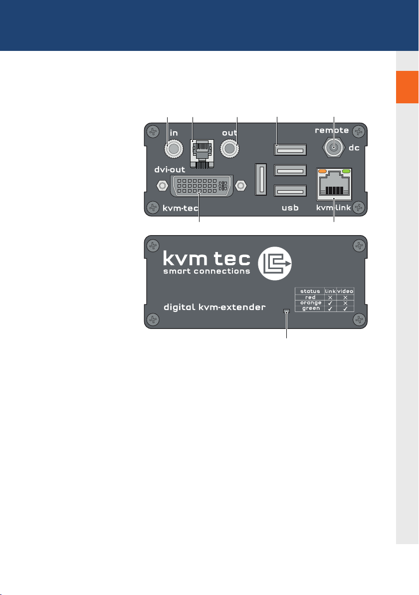
1. introduction
1
Remote Extender (CON)
RS232
matrixline fibre
Nr. Name Function
9 in Audio In from microphone etc.
10 out Audio Out to speakers etc.
11 usb USB connections (e.g. for keyboard and mouse)
12 dc Connection for 12 V power supply
13 kvm-link/ RJ45 socket Connection for CAT5/6/7 cable or ber cable
14 dvi-out DVI-D connection to monitor
15 Power/Status LED Displays the status of the extender
1310 11 12
17
14
1516
kvm-tec | 11

1. introduction
1.5 MEANING OF LED INDICATORS
The Status LED (8/15) can light red, orange or green. Table 1 shows the meaning of each colour.
Also see chapter Troubleshooting.
Normal Operation
Colour Blinking Physical
Main LED
Red - Yes No No Update Failed
Red Slow No No No
Orange - Yes Yes No
Orange Fast Update in Progress
Green - Ye s Yes Ye s Update Succedded
Green V. fast Yes**
Red/Green V. fast Yes
RJ45 Socket LEDs *
Yellow - No
Yellow Slow Yes
Green - Yes
Green V. fast Yes
Link
Active
Connection
Video
Extended
USB
Initialisation
UBS Data
Received
Identify
Command
Autoupdate
Mode
* MX only ** Rem. Only
Table 1: Meaning of LED indicators
12 | kvm-tec

2. INSTALLATION OF THE EXTENDER
2.1 UNPACKING AND CHECKING
THE CONTENTS
Before using the product for the rst time it should be checked for damage. In case of damage due to
transport inform the carrier immediately. Before delivery the product is checked for its function and its
operating safety.
• Make sure that the packaging contains the following content:
A. 1x MX 2000/local extender/CPU
B. 1x MX 2000/remote extender/CON
LOCAL /CPU Unit
1 x wall power supply unit l 12V 1A (EU-plug or INT plug)
1 x DVI - DVI cable 1,8m/5.9ft
1 x USB cable 1,8m/5.9ft
1 x VGA-DVI cable 1,8m/5.9ft (opt)
2 x Audio cable 1,8m /5.9ft (opt)
1 x RJ11 to Sub9 (RS232) Adapter
1 x RS 232 extension cable 1,8m/5.9ft
4 x rubber feet
4 x mounting pads
REMOTE/CON Unit
1 x wall power supply unit l 12V 1A (EU-plug or INT plug)
1x RJ11 to Sub9 (RS232) Adapter
4 x rubber feet
4 x mounting pads
2
MX 2000 Fiber SFP Module pro unit
1 x SFP Modul-Multimode module up to 500m/1640 ft
(alternativ with Single-Mode up to 20km/12 mi ItemNr 6855)
kvm-tec | 13

2. INSTALLATION Of The exTeNder
2.2 MOUNTING OPTIONS
2.2.1 MOUNTING PADS AND RUBBER FEET
The mounting pads and rubber feet can be used to hold the extenders in place and prevents
them from sliding and falling.
To attach the mounting pads or rubber feet:
1. Remove the protection layer from the mounting pads or rubber feet (G).
2. Attach the mounting pads or rubber feet (G) to the bottom the units.
2.2.2 MOUNTING KITS (OPTIONAL)
The following mounting kits are available:
Rack Mounting Kit RMK-F - Part No. 6130
The rack mounting kit RMK-F is for mounting kvm-tec Marixline extenders. It consists of a19“
rack shelf and an alu-faceplate.
Rack Mounting Kit RMK-FN - Part No. 6131
The rack mounting kit RMK-FN is for assembling kvm-tec Matrixline extenders. It consists of 19“
Rack Shelf, an alu-faceplate and a power supply.
Rack Mounting Kit RMK-FRN - Part No. 6132
The rack mounting kit RMK-FRN is used to mount kvm-tec Matrixline extenders. It is equipped
with rack shelf, faceplate and 2 power supply units, which are summarized in a redundancy
module.
Under Desk Mounting Kit - Part No. 6135
The Under Desk Mounting kit is for underdesk mounting of the MX extender.
Din Rail Mounting Kit - Part No. 6136
The DIN rail mounting is used for space-saving installation in control cabinets or on DIN rails.
The attachment to the MX extenders is possible in several ways.
14 | kvm-tec
2. INSTALLATION Of The exTeNder
2.3 INSTALLING THE EXTENDER
WARNING! Read and understand all safety information before installing the product.
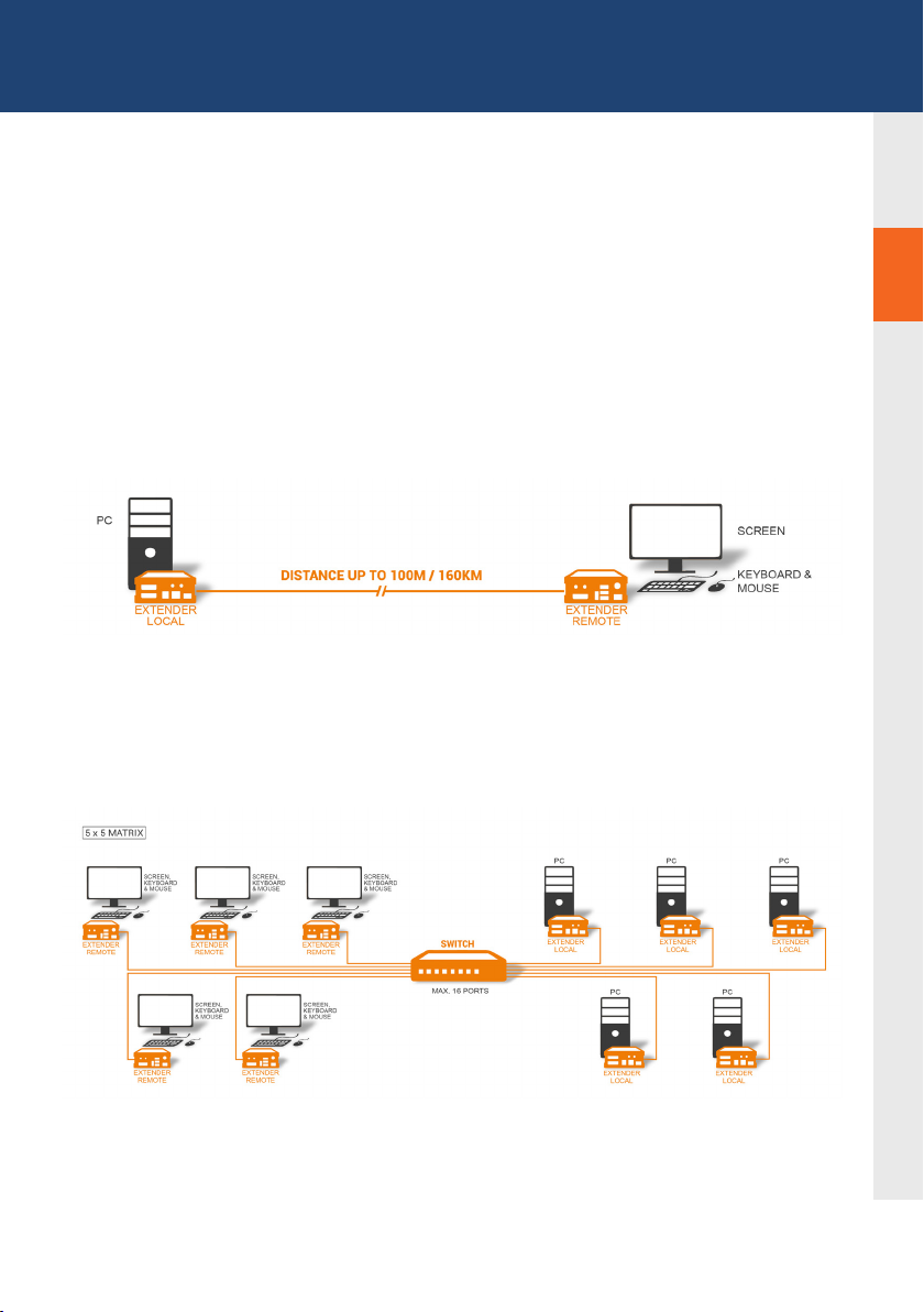
The units can be set up to access one host computer, or to access numerous host computers.
In the case of the latter, an additional Network Switch must be installed. With a Network Switch,
each user can gain quick access to any of the required computers.
2
2
point to point connection
Set up for Switching System up to 480 endpoints
Set up for Switching Sysetm up to 480 endpoints
kvm-tec | 15
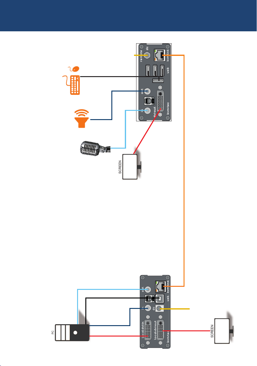
2. INSTALLATION OF THE EXTENDER
1. Power plug
12V 1A
2. USB from
Keyboard and mouse
5. Audio to
Speaker
6. Audio from
Microphone
RS232
matrixline fibre
4. DVI to Monitor
3. Network cable CAT5e/6 up to 150m/492ft
16 | kvm-tec
6. Audio to PC
2. USB to PC
5. Audio
from PC
4. DVI in
from PC
RS232
matrixline fibre
4. DVI out
to Monitor
1. Power plug
12V 1A

2. INSTALLATION Of The exTeNder
Quick Installation MX2000 MASTERLINE
local / CPU – remote/ CON
1. Connect the CON / Remote and the CPU / Local Unit to the
included 12V 1A power supply.
2. Now connect the USB cable to a USB port on your PC and
connect the other end of the USB cable to the CPU / Local
Unit. Connect keyboard and mouse to the CON / Remote
Unit.
3. Connect the CPU / Local and the CON / Remote Unit with a
network cable.
4. Now connect the HDMI-DVI cable to the DVI socket of the PC
and the other end to the HDMI socket of the CPU Local Unit
(PC-in). Then connect the monitor with the HDMI-DVI cable to
the CON / Remote Unit.
HAVE FUN - your kvm-tec Extender is now in use for many
years ( MTBF approx 10 years)
2
kvm-tec | 17
 Loading...