

USER-MANUAL
SMARTLINE SVX1
Matrixline 2000
IP
KVM Extender over
www.kvm-tec.com
MATRIXLINE MX
6711L CPU/LOCAL
6711R CON/REMOTE
MASTERLINE MVX1/MVX1-F KVM EXTENDER
Check out our
Installation Channel:
MATRIXLINE FIBER MX-F
6811L CPU/LOCAL
6811R CON/REMOTE

TABLE OF CONTENT
TABLE OF CONTENTS
1. introduction 6
1.1 Intended Use 6
1.2 Safety Instructions 7
1.3 Technical Specications 9
1.4 Product elements 10
1.5 Meaning of LED indicators 12
2. Installation of the Extender 13
2.1 Unpacking and checking the contents 13
2.2 Mounting options 14
2.2.1 Mounting pads and rubber feet 14
3. Extender SETTINGS 22
3.1 How to access the main menu 22
2 | kvm-tec
2.2.2 Mounting kits (optional) 14
2.3 Installing the extender 15
2.4 Startup 20
2.5 Replacing the SFP module 20
2.6 Removing a CATx cable 21
2.7 Removing a ber cable 21
3.1 How to access the main menu 22

TABLE OF CONTENT
3.2 Status Menu 23
3.3 Display rmware version 23
3.4 Performing a rmware update 24
3.5 DDC Menü 25
3.6 Display unit list 26
3.7 Favorite list 27
3.8 Share list 28
3.9 How to change the extender settings 29
3.9.1 Changing local settings 30
3.9.2 Changing Remote settings 30
3.9.3 how to optimize vga preferences 31
3.9.4 How to set the audio volume 32
3.9.5 Congure a baud rate for the serial RS232 connection 33
3.9.6 Show the last received image 35
3.9.7. How to use the power saving mode 36
3.9.8. How to select your type of keyboard 37
3.9.9 How to change keyboard fallback mode 38
3.9.9 Keyboard Fallback Modus wechseln
3.9.10 How to change keyboard shortcuts 39
3.9.11 Close extender menu 39
3.9.12 Hide display status screen
40
kvm-tec | 3

TABLE OF CONTENT
3.10 How to switch betwee different computers 41
3.11 Video sharing 41
4. Network settings 43
4.1 Network settings and Management Switching Systems 43
4.2 Connecting,disconnecting or select a current workplace
connected devices 43
5. Maintance and care 44
6. Troubleshooting 44
7. Disposal 45
8. Warranty 46
9. Support 46
10. Declaration of conformity 47
11. Cable requirements 49
4 | kvm-tec
11.1 Requirements for CAT5e/6/7 cables 49
11.2 Requirements ber cables 50
11.2.1 Multi-Mode (standard) 50
11.2.2 Single-Mode (optional) 50
12 Requirements network switch 50

TABLE OF CONTENT
13. First aid 52
14. Extended warranty 53
15. Notes 54
kvm-tec | 5

1. INTRODUCTION
Congratulations on the purchase of your new Masterline MX/MX-F KVM Extender. You
have bought a high quality extender. These instructions are part of this product. They
contain important information regarding safety, use and disposal for every user of the
Matrixline MX2000 and MX2000-F KVM Extender. Please familiarise yourself with the
information within prior to using your product. Use the product only in the manner as
described and for the areas of application as stated. When passing the product to a third
party be sure to also supply all instructions and other relevant documentation. Following
proper use and maintenance, your Matrixline MX2000/MX2000-F KVM Extender will bring
you joy for many years to come.
1.1 INTENDED USE
This product is intended to be used as a device to increase the distance that a keyboard,
monitor and mouse can be placed from a computer. This product is intended for professional
use. The product should not be used in potentially explosive environments.
The product may only be used according to the instructions as described in this manual. All
use, other than that described in this manual, is seen as unintended use. Modications in the
course of technological progress are reserved. In these user instructions the Matrixline
MX/MX-F KVM Extender is referred to as ‘product’ or ‘extender‘. The MX/PC is referred to as the
‘local unit’ and the MX/Monitor is referred to as the ‘remote unit‘.
6 | kvm-tec

1. introduction
1.2 SAFETY INSTRUCTIONS
WARNING! Read and understand all safety instructions.
• Follow all the instructions. This will avoid accidents, re, explosions, electric shocks or
other hazards that may result in damage to property and/or severe or fatal injuries.
Please ensure that everyone who uses the product has read and followed these warnings
and instructions.
• Keep all safety information and instructions for future reference and pass them on to
subsequent users of the product.
• The manufacturer is not liable for cases of material damage or personal injury caused
by incorrect handling or non-compliance with the safety instructions. In such cases, the
warranty will be voided.
• This product is not intended for use by persons (including children) with restricted
physical, sensory or intellectual capability or lack of experience and/or knowledge, unless
they are supervised by a person who is responsible for their safety or provides them with
instructions on how to use the product.
• DANGER! Not for use in potentially explosive environments.
• DANGER! Be vigilant at all times, and always take care around this product. Do not use
electrical equipment if you are lacking in concentration or awareness, or are under the
inuence of drugs, alcohol or medication. Even a moment of inattentiveness can lead to
serious accidents and injuries when using electrical equipment. Check the product and
the cables for any damage before use. If there is any visible damage, a strong odour, or
excessive overheating of components unplug all the connections immediately and stop
using the product.
• DANGER! The MX-F KVM Extender is a Class 1 Laser Product 1 according to
DIN 40008/EN and VDE 0837.
• If the product is not installed and used in accordance with this manual, it may cause
disruptive interference with radio or television reception or affect other electronic
products in residential areas.
• Use shielded cables only to connect the components in order to avoid such interference.
Non-compliance invalidates the permission to operate this product.
• Only the mains adapter included with the product should be used as the power supply.
Do not use other adapters.
• Prior to connecting to the mains, make sure your local mains voltage matches the rating
indicated on the product.
• The product must be connected to a permanent and earthed AC wall socket.
1
kvm-tec | 7

1. introduction
• Protect cables from being strained, pinched or buckled and place them in a way to
prevent people from tripping over the cord.
• In particular, ensure to avoid damage to the mains adapter.
• Use the product with a suitable, properly installed and easily accessible mains power
socket. Make sure the product can be disconnected from the power socket at all times.
• Unplug the product during electrical storms or when not in use.
• DANGER! Never touch the adapter with wet hands.
• Use the product within the specied performance limits.
• Keep the product away from ammable materials such as curtains and drapes.
• Protect the mains adapter from use by third parties (particularly children). Keep the
unused mains adapter in a dry, elevated or locked location away from children.
• Do not place the product near heaters.
• Do not drop or hit the product.
• Unplug all connections before cleaning the product. Do not use wipes or chemicals
as these could damage the surface. Wipe the housing with a damp cloth. Electrical/
electronic parts must not be cleaned.
• Alterations to the product and technical modications are not permitted.
8 | kvm-tec

1. introduction
1.3 TECHNICAL SPECIFICATIONS
Type: KVM Extender (local unit and remote unit)
Model: Matrixline MX2000 und Matrixline 2000 Fiber MX-F KVM
Extender
Power supply input voltage: 100 - 240 V; 50/60 Hz AC
Power supply output: 12V; 1A (external power supply)
Power requirement: 6W per extender (excluding attached USB devices)
Operating temperature range: 0 ºC to 45 ºC / 32 °F to 113 °F
Storage temperature range: −25 ºC to 80 ºC / −13 °F to 176 °F
Relative humidity: max. 80% (non-condensing)
1
Storage humidity: max. 80% (non-condensing)
Casing Material: Anodized aluminium
Dimensions: approx. 97,5 x 41 x 103,5 mm / 3.83x 1.57 x 4.7 inch ”
Weight: local unit 302g/0.66lbs.
remote 291g/0.64lbs
Expected product life: 82 820 hours / 9.5 years
Laser MVX1-F: Class 1 Laser Product 1 according to DIN 40008/EN and
VDE 0837
kvm-tec | 9
1. introduction
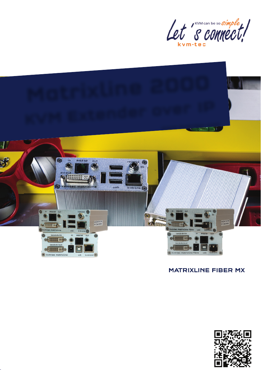
1.4 PRODUCT ELEMENTS
Local Extender (CPU)
Nr. Name Function
1 dvi-in DVI connection to PC
2 in Audio In from PC
3 out Audio Out to PC
4 kvm-link/ RJ45 socket Connection for CAT5/6/7 cable or ber cable
5 usb USB connection
6 dc Connection for 12 V power supply
7 dvi-out DVI connection to monitor
8 Power/Status LED Displays the status of the extender
1
matrixline fibre
8
2
3
RS232
7
9
6 5
4
10 | kvm-tec
1. introduction
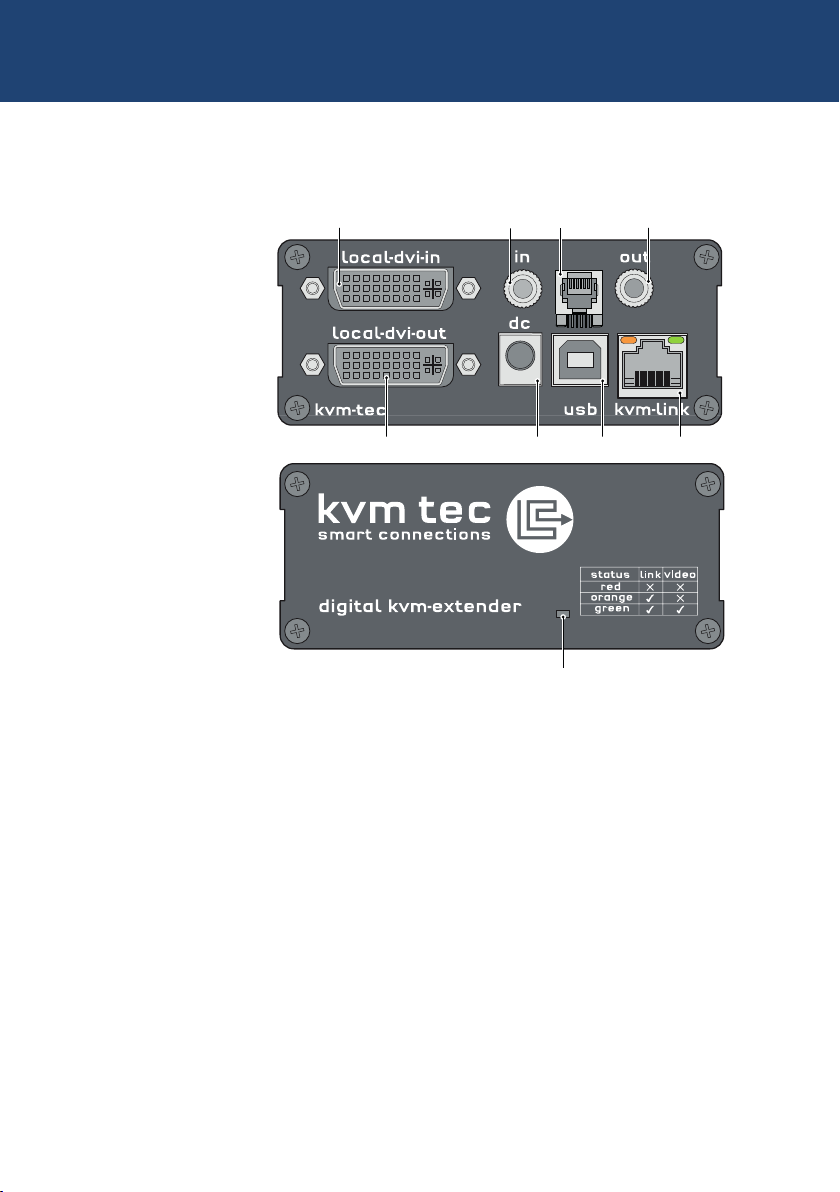
1
Remote Extender (CON)
RS232
matrixline fibre
Nr. Name Function
9 in Audio In from microphone etc.
10 out Audio Out to speakers etc.
11 usb USB connections (e.g. for keyboard and mouse)
12 dc Connection for 12 V power supply
13 kvm-link/ RJ45 socket Connection for CAT5/6/7 cable or ber cable
14 dvi-out DVI-D connection to monitor
15 Power/Status LED Displays the status of the extender
1310 11 12
17
14
1516
kvm-tec | 11

1. introduction
1.5 MEANING OF LED INDICATORS
The Status LED (8/15) can light red, orange or green. Table 1 shows the meaning of each colour.
Also see chapter Troubleshooting.
Normal Operation
Colour Blinking Physical
Main LED
Red - Yes No No Update Failed
Red Slow No No No
Orange - Yes Yes No
Orange Fast Update in Progress
Green - Ye s Yes Ye s Update Succedded
Green V. fast Yes**
Red/Green V. fast Yes
RJ45 Socket LEDs *
Yellow - No
Yellow Slow Yes
Green - Yes
Green V. fast Yes
Link
Active
Connection
Video
Extended
USB
Initialisation
UBS Data
Received
Identify
Command
Autoupdate
Mode
* MX only ** Rem. Only
Table 1: Meaning of LED indicators
12 | kvm-tec

2. INSTALLATION OF THE EXTENDER
2.1 UNPACKING AND CHECKING
THE CONTENTS
Before using the product for the rst time it should be checked for damage. In case of damage due to
transport inform the carrier immediately. Before delivery the product is checked for its function and its
operating safety.
• Make sure that the packaging contains the following content:
A. 1x MX 2000/local extender/CPU
B. 1x MX 2000/remote extender/CON
LOCAL /CPU Unit
1 x wall power supply unit l 12V 1A (EU-plug or INT plug)
1 x DVI - DVI cable 1,8m/5.9ft
1 x USB cable 1,8m/5.9ft
1 x VGA-DVI cable 1,8m/5.9ft (opt)
2 x Audio cable 1,8m /5.9ft (opt)
1 x RJ11 to Sub9 (RS232) Adapter
1 x RS 232 extension cable 1,8m/5.9ft
4 x rubber feet
4 x mounting pads
REMOTE/CON Unit
1 x wall power supply unit l 12V 1A (EU-plug or INT plug)
1x RJ11 to Sub9 (RS232) Adapter
4 x rubber feet
4 x mounting pads
2
MX 2000 Fiber SFP Module pro unit
1 x SFP Modul-Multimode module up to 500m/1640 ft
(alternativ with Single-Mode up to 20km/12 mi ItemNr 6855)
kvm-tec | 13

2. INSTALLATION Of The exTeNder
2.2 MOUNTING OPTIONS
2.2.1 MOUNTING PADS AND RUBBER FEET
The mounting pads and rubber feet can be used to hold the extenders in place and prevents
them from sliding and falling.
To attach the mounting pads or rubber feet:
1. Remove the protection layer from the mounting pads or rubber feet (G).
2. Attach the mounting pads or rubber feet (G) to the bottom the units.
2.2.2 MOUNTING KITS (OPTIONAL)
The following mounting kits are available:
Rack Mounting Kit RMK-F - Part No. 6130
The rack mounting kit RMK-F is for mounting kvm-tec Marixline extenders. It consists of a19“
rack shelf and an alu-faceplate.
Rack Mounting Kit RMK-FN - Part No. 6131
The rack mounting kit RMK-FN is for assembling kvm-tec Matrixline extenders. It consists of 19“
Rack Shelf, an alu-faceplate and a power supply.
Rack Mounting Kit RMK-FRN - Part No. 6132
The rack mounting kit RMK-FRN is used to mount kvm-tec Matrixline extenders. It is equipped
with rack shelf, faceplate and 2 power supply units, which are summarized in a redundancy
module.
Under Desk Mounting Kit - Part No. 6135
The Under Desk Mounting kit is for underdesk mounting of the MX extender.
Din Rail Mounting Kit - Part No. 6136
The DIN rail mounting is used for space-saving installation in control cabinets or on DIN rails.
The attachment to the MX extenders is possible in several ways.
14 | kvm-tec
2. INSTALLATION Of The exTeNder
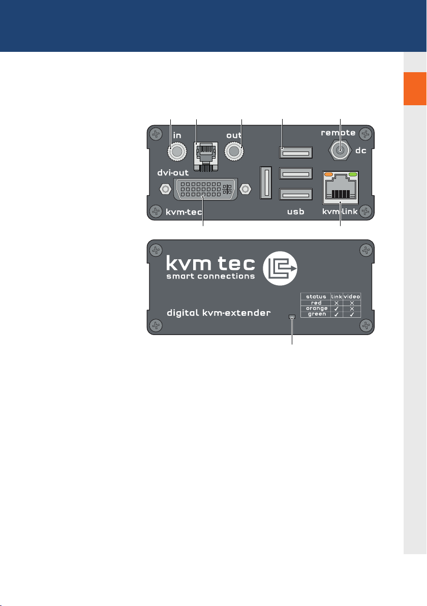
2.3 INSTALLING THE EXTENDER
WARNING! Read and understand all safety information before installing the product.
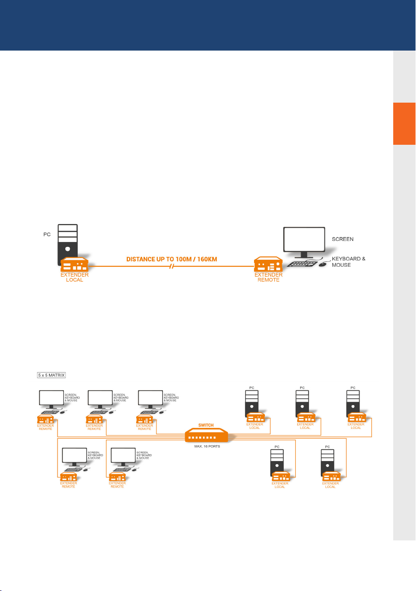
The units can be set up to access one host computer, or to access numerous host computers.
In the case of the latter, an additional Network Switch must be installed. With a Network Switch,
each user can gain quick access to any of the required computers.
2
2
point to point connection
Set up for Switching System up to 480 endpoints
Set up for Switching Sysetm up to 480 endpoints
kvm-tec | 15
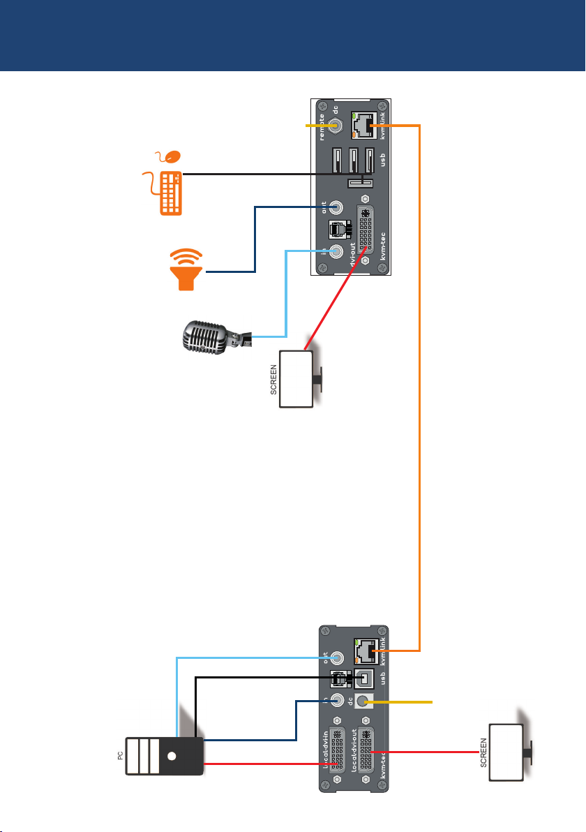
2. INSTALLATION OF THE EXTENDER
1. Power plug
12V 1A
2. USB from
Keyboard and mouse
5. Audio to
Speaker
6. Audio from
Microphone
RS232
matrixline fibre
4. DVI to Monitor
3. Network cable CAT5e/6 up to 150m/492ft
16 | kvm-tec
6. Audio to PC
2. USB to PC
5. Audio
from PC
4. DVI in
from PC
RS232
matrixline fibre
4. DVI out
to Monitor
1. Power plug
12V 1A

2. INSTALLATION Of The exTeNder
Quick Installation MX2000 MASTERLINE
local / CPU – remote/ CON
1. Connect the CON / Remote and the CPU / Local Unit to the
included 12V 1A power supply.
2. Now connect the USB cable to a USB port on your PC and
connect the other end of the USB cable to the CPU / Local
Unit. Connect keyboard and mouse to the CON / Remote
Unit.
3. Connect the CPU / Local and the CON / Remote Unit with a
network cable.
4. Now connect the HDMI-DVI cable to the DVI socket of the PC
and the other end to the HDMI socket of the CPU Local Unit
(PC-in). Then connect the monitor with the HDMI-DVI cable to
the CON / Remote Unit.
HAVE FUN - your kvm-tec Extender is now in use for many
years ( MTBF approx 10 years)
2
kvm-tec | 17

2. INSTALLATION OF THE EXTENDER
Power plug
12V 1A
2. USB from
Keyboard and mouse
5. Audio to
Speaker
6. Audio from
Microphone
4. DVI to Monitor
RS232
matrixline fibre
3. Network cable Duplex Multimode Fiber up to 500m/1640ft
18 | kvm-tec
6. Audio to PC
2. USB to PC
5. Audio
from PC
4. DVI in
from PC
RS232
matrixline fibre
4. DVI out
to Monitor
Power plug
12V 1A

2. INSTALLATION Of The exTeNder
Quick Installation MX2000 MASTERLINE FIBER local / CPU – remo-
te/ CON
1. Connect the CON / Remote and the CPU / Local Unit to the included 12V 1A
power supply.
2. Now connect the USB cable to a USB port on your PC and connect the other
end of the USB cable to the CPU / Local Unit. Connect keyboard and mouse
to the CON / Remote Unit.
3. Connect the CPU / Local and the CON / Remote Unit with a ber cable.
4. Now connect the DVI cable to the DVI socket of the PC and the other end to
the DVI socket of the CPU / Local Unit (DVI-in). Then connect the monitor to
the CON / Remote Unit with a DVI cable.
5. Then connect PC audio out with the audio cable to Local Audio in. Then
connect audio / out via the audio cable
6. Almost done! Now connect the audio cable Local Audio / out to the PC Audio
in and Remote Audio / out with the audio cable to the microphone
HAVE FUN - your kvm-tec Extender is now in use for many years ( MTBF approx 10 years)
kvm-tec | 19

2. INSTALLATION OF THE EXTENDER
2.4 STARTUP
To start up the system without switch:
1. Make sure that the two monitors and the computer are switched on.
2. If you are using a Network Switch, connect the power supply to an earthed wall socket.
3. Connect both extender power supplies (C) to an earthed wall socket. Both extenders will
start an initialisation process. The red status LED blinks a few seconds. After a few seconds
the status LED lights green. The monitor will displays your computer’s desktop or any open
applications.
2.5 REPLACING THE SFP MODULE
The MVX1-F is delivered with a multimode SFP module.
To replace an SFP module with a different SFP module:
1. Remove the black dust protector from the SFP module.
2. Pull the metal latch of the SFP module forwards until it is at a right angle.
3. Replace the SFP module with the other module. Put the metal latch back in position. Only
use SFP modules from kvm-tec, or recommended by kvm-tec.
20 | kvm-tec

2. INSTALLATION OF THE EXTENDER
2.6 REMOVING A CATX CABLE
To remove a CATx cable:
• Press the latch down and slowly pull the cable out.
2.7 REMOVING A FIBER CABLE
To remove a ber cable:
• Press the latch down and slowly pull the cable out.
2
kvm-tec | 21

3. EXTENDER sETTiNgs
3. EXTENDER SETTINGS
3.1 HOW TO ACCESS THE MAIN MENU
Use the monitor and keyboard to get access to the main menu.
To access the main menu:
1. Make sure the extenders, the monitors and the computer are switched on.
2. Press the Scroll Lock key on your keyboard quickly ve times. The main menu appears
with an overview of the sub-menus.
3. To access a sub-menu press the applicable key.
In the main menu, you can make the following settings by pressing the
to select the corresponding letter.
T Status Overview Menu Status / Current Status:
U Update Flash FW Update rmware
M Option Overview Overview of all upgrades
O DDC Option DDC Option Fixed ice position 1020 x 1080
W Network Settings Network Settings
G ExtenderSettings Settings Extender
L Switching List List of all extenders in the switching system
Q Exit Exit
22 | kvm-tec
kvm-tec | 22

3. EXTENDER sETTiNgs
3.2 STATUS MENU
In the “Status Menu” the current status of the extender connection is displayed. It provides
information on the connection itself as well as resolution of the video channel, and USB-status.
3
The enabled options and the current FW-version is displayed in the left top corner.
Link status shows whether there is a physical connection available. Connection indicates if kvm
data is currently able to be transmitted.
Video and USB show if data is currently being transmitted.
3.3 DISPLAY OF FIRMWARE VERSION
• Make sure that the main menu is open. The currently installed rmware version of the
remote (CON) and local (CPU) extender is displayed below (e.g. ‚4267‘).
kvm-tec | 23

3. EXTENDER SETTINGS
3.4 PERFORMING A FIRMWARE
UPDATES VIA THE SWITCHING MANAGER
Update management is carried out via the Switching Manager software included in the delivery
see User Manual Switching Manager 2000 chapter 9.2 ( p 44)
n this view, all extenders for which a rmware update is to be performed are displayed.
This function displays a list of the extenders that are assigned to the Switching Manager.
Updating the extenders in the system is a two-step process. In the rst step the rmware is
loaded onto the device and in the second step the update is performed. All extenders in the
ystem le can also be updated together.
For the update, activate the Settings window and select the folder from which the rmware le is
to be uploaded. The list of bitamps is displayed under MX Firmware.
Then transfer the rmware and the update will be done in two steps. 1:
1. send the rmware to the Extender.
It takes about 2 minutes until the rmware is loaded into the Extender. The bar on the right in
the column
the main window lls blue
2. is the update.
ATTENTION Only if the bar is grey, the update is nished.
24 | kvm-tec

3. EXTENDER sETTiNgs
3.5 DDC MENÜ
The DDC Option menu allows the user to dene what DDC information is used by the PC.
To dene what DDC information is used by the PC:
1. Make sure the main menu is open.
2. Press the O key. The DDC Option menu appears.
• Press 0 to use the DDC information from the monitor attached to the r
emote extender.
• Press 2 to save the current DDC information. The system uses the same settings
after the extender has been restarted.
• Press 4 through 8 to use a predened resolution which is saved.
3. Press ESC to go back to the main menu.
3
kvm-tec | 25

3. EXTENDER sETTiNgs
3.6 DISPLAY UNIT LIST
Available devices to which the user can connect are displayed here. wc verfügbaren Geräte
angzeigt, mit denen sich derBenutzer verbinden kann.
26 | kvm-tec

3. EXTENDER sETTiNgs
3.7 FAVORITE LIST
A total of 8 favorites can be dened. Connecting these 8 favorites is possible with shortcuts
from 1-8.
kvm-tec | 27

3. EXTENDER sETTiNgs
3.8 SHARE LIST
Displays all extenders that can be shared. The current screen of the work center can be shared
with other remote units via this list.
28 | kvm-tec

3. EXTENDER sETTiNgs
3.9 HOW TO CHANGE THE EXTENDER
SETTINGS
The Extender Settings menu allows the user to change a range of further preferences. Three
of the selections (VGA, Audio and RS232) will take you to sub-menus. The other four can be
enabled or disabled by pressing the applicable key.
To access the Extender Settings menu:
1. Make sure the main menu is open.
2. Press the G key. The Extender Settings menu appears.
3. The extender settings are distributed across two sub-menus: Remote Settings and
Local Settings.
3
kvm-tec | 29
3. EXTENDER sETTiNgs
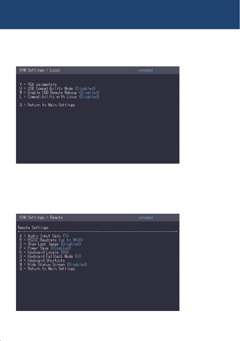
3.9.1 CHANGING LOCAL SETTINGS
.
Display local or remote extender settings:
- Press the L button to display the Local Setting menu.
3.9.2 CHANGING REMOTE SETTINGS
• Drücken Sie die R Taste um das Remote Setting Menü anzuzeigen.
• Press R button to display the Remote Setting menu
30 | kvm-tec

3. EXTENDER sETTiNgs
3.9.3 HOW TO OPTIMIZE VGA PREFERENCES
The VGA preferences can be set and optimized. The VGA option does only function when it has
been unlocked (see 3.4).
To optimize the VGA settings:
1. From the Extender Settings menu, press the L key. The Local Settings menu appears.
2. Press the V key. The VGA menu appears.
• Press F1 to move the display area up.
• Press F4 to move the display area down.
• Press F2 to move the display area to the left.
• Press F3 to move the display area to the right.
• Press F5 to zoom out.
• Press F6 to zoom in.
• Press space to change the rate of the above mentioned setting. This toggles the rate
of change between 1 and 10.
• Press M to switch the video mode between:
• Auto – the mode is automatically detected and set by the extender.
• DVI – only DVI input is detected.
• VGA – only VGA input is detected.
• Press K for automatic adjustment and positioning of the image area.
• Press I to reset parameters to default values.
• Press S to save the settings and exit the menu.
• Press Q to exit without saving.
3
kvm-tec | 31
3. EXTENDER sETTiNgs
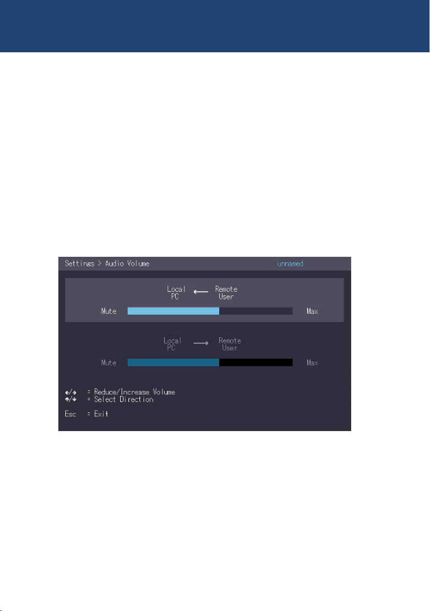
3.9.4 HOW TO SET THE AUDIO VOLUME
The volume of the audio input (microphone) on the remote unit can be changed. The default
value is 5 but can be set to any value in between 0 and 9. At 0 the audio input on the remote
unit is disabled.
To set the volume:
1. From the Extender Settings menu, press the R key. The Remote Settings menu
appears.
2. Press the A key. The Audio Input Gain menu appears.
Press arrow left / right to change volume
Press arrow up / down to set directio
32 | kvm-tec

3. EXTENDER sETTiNgs
3.9.5 CONFIGURE A BAUD RATE FOR THE SERIAL
RS232 CONNECTION
3
Setting the baud rate with activated RS232 upgrade
1. In the extender settings menu, press the R button. The Remote Settings Menu is displayed.
2. Press the R button. 2. The Baud Rate menu is displayed.
3. To select a baud rate, press the corresponding key.
4. The Enter Parity menu opens.
5. Press the appropriate button to select a parity rate.
kvm-tec | 33

3. EXTENDER sETTiNgs
Local Unit (CPU) Pinout (DCE):
Pin Function direction
2 TxD OUT
3 RxD IN
4 DTR IN
5 GND —
8 CTS OUT
The pin numbers refer to a 9-pin D-sub plug.
The baud rate can be set in the menu. There is a universal setting for baud rates up to 9600
which transmits all different RS232 congurations transparently. For higher baud rates the
following settings are available via the menu:
Baudrate Parity Stopbits
4800 No 1
9600 Odd 2
19200 Even
38400 Mark
57600 Space
115200
230400
Remote Unit (CON)Pinout (DTE):
Pin Function direction
2 RxD IN
3 TxD OUT
4 DTR OUT
5 GND —
8 CTS IN
34 | kvm-tec

3. EXTENDER sETTiNgs
3.9.6 SHOW THE LAST RECEIVED IMAGE
With the function „show the last image“ the last received image can be used instead of a black
screen, if the remote Extender (CON) is not being used by the local
Extender (CPU) are separated. To show that this is the last received picture
the frame of the image ashes red.
Activate or deactivate the „Show last Image“ function. 1:
1. In the Extender Settings menu, press the R button. The Remote Settings menu becomes
Press S to activate or deactivate the function.
2. press S to activate or deactivate the function.
3. press ESC to return to the main menu.
3
kvm-tec | 35

3. EXTENDER sETTiNgs
3.9.7. HOW TO USE THE POWER SAVING MODE
The power saving mode lets the extender turn off its video out when the remote extender does
not receive a video signal for more than a minute.
To turn on or off the power saving mode:
1. From the Extender Settings menu, press the R key. The Remote Settings menu appears.
2. Press the P key to enable or disable the power saving mode.
3. When in power saving mode, press any key to return to the menu.
36 | kvm-tec

3. EXTENDER sETTiNgs
3.9.8. HOW TO SELECT YOUR TYPE OF KEYBOARD
The Keyboard Local menu lets you switch between keyboard layouts for navigating the on
screen display menu (OSD). You can choose between French (Azerty), English (Qwerty) and
German (Qwertz).
To select a keyboard layout:
1. From the Extender Settings menu, press the R key. The Remote Settings menu appears.
2. Press the K key. The Keyboard Locale menu opens:
• Press E to select English (QWERTY)
• Press D to select German (QWERTZ)
• Press F to select French (AZERTY)
3
kvm-tec | 37

3. EXTENDER sETTiNgs
3.9.9 HOW TO CHANGE KEYBOARD FALLBACK MODE
In the Keyboard Locale menu, you can switch between keyboard layouts to navigate the On
Screen Display (OSD) menu. You can choose between Francais (Azerty), English (Qwerty) and
German (Qwertz).
38 | kvm-tec

3. EXTENDER sETTiNgs
3.9.10 HOW TO CHANGE KEYBOARD SHORTCUTS
The Keyboard Shortcuts menu lets you edit the preferred shortcuts for common commands.
To edit the shortcuts:
1. From the Extender Settings menu, press the R key. The Remote Settings menu appears.
2. Press the H key. The Keyboard Shortcuts menu opens.
3. Use the arrows to select a command.
4. Press E to edit the shortcut.
To edit:
• Press a single key. Edit the frequency with left and right arrows.
OR -
• Press a key combination
3
3.9.11 CLOSE EXTENDER MENU
So close the Extender Settings menu:
• Press Q to close the Extender Settings menu.
kvm-tec | 39

3. EXTENDER sETTiNgs
3.9.12 HIDE DISPLAY STATUS SCREEN
Press N in the Remote Settings menu.
This will remove the status screen and the image chimr remains black.
40 | kvm-tec

3. EXTENDER sETTiNgs
3.10 HOW TO SWITCH BETWEEN
DIFFERENT COMPUTERS
The menu for switching between different computers is possible via a connected USB keyboard,
which is connected to the remote/CON unit. This function is only possible in combination with a
network switch and the included software Switching Manager.
1. press Ctrl+Alt+F12 (this is the default key combination, but it is not possible to use it)
can be changed. „See chapter „Changing key combinations“).
This opens the switching menu. The switching menu lists all local/CPU units that are
connected to the switching network. 2.
2. to select a local extender press arrow up and down, or PG/UP and PGD/OWN buttons.
Press Enter. The system switches to the selected Computer down.
3. with F1 - F8 favorites can be created and selected.
3.11 VIDEO SHARING
3
see chapter 3.8 Share List
kvm-tec | 41

3. EXTENDER SETTINGS
42 | kvm-tec
Videosharing

4. NETWORK SETTINGS
4.1 NETWORK SETTINGS AND
MANAGEMENT SWITCHING SYSTEMS
All network settings, user administration and extender management are done via the included
Switching Manager software and all functions are described in the Swiitching Manager 2000
manual. You can download the manual from our website. www. kvm-tec.com
4.2 CONNECTING,DISCONNECTING OR
SELECT A CURRENT WORKPLACE
CONNECTED DEVICES
The Overview screen provides an overview of the currently connected PCSs, as well as the free
PCs and consoles on the network. You can remotely cancel a connection, assign a new console
to a PC, or vice versa.
Press D to disconnect the devices.
By pressing P a point-to-point connection can be activated.
Press A Log In Form. By entering your username and password, you can log in directly to a
remote workstation.
The general user administration is done in the Switching Manager software. After logging in,
the user receives his personalized lists ( Devices, Favorites Lsite).
4
kvm-tec | 43

5. MAINTANCE AND CARE
CAUTION! Do not use solvent-containing cleansers. Do not use wipes, alcohols (e.g. spiritus) or
chemicals as these could damage the surface.
To clean the product:
• Clean the product with a maintenance product for synthetic material, which is available in
specialized shops.
6. TROUBLESHOOTING
Error Cause Solution
LED is not
lighting
LED is lighting
in red
LED is lighting
in orange
LED is lighting
green
LED is lighting
green
The devices get no
power
No connection
between Loc and
Rem
No picture on the
monitor
Screen occurs but
the keyboard is not
working
No audio Establish audio connection:
Is the power supply connected? (white box)
Check if the RJ45/network cable is connected well.
(Clicking noise when plugging in)
Control both, if it does not work please send an e-mail to
support@kvm-tec.com
Check if the local (PC) cable is connected well.
Check if the remote (monitor) cable is connected well.
If everything is connected well but no function appears,
reconnect power supply again.
If the menu is visible, press the O key and choose the
resolution of the monitor. Then press the assigned
number on your keyboard.
Plug out/in USB of keyboard and wait until driver is
installed (after few seconds).
Check all USB connections on both sides (Local and
Remote)
If it is still not working, plug out/in DC once more
plug stereo-jack to the audio output of the PC (green)
connection with local: IN
remote: headset OUT
Establish microphone connection:
plug stereo-jack to the microphone input of the PC (pink)
connection with local OUT. Connect the microphone to
the Remote IN
44 | kvm-tec
6. TROUBLESHOOTING
Error Cause Solution
LED is lighting
green
LED is blinking
green
LED are
lighting
differently
The screen fl ickers,
has an incorrect
display
Different fi rmware
or USB is not
compatible
Different fi rmware
Install current rmware from our homepage www.kvm-
tec.com/support
Please contact the kvm-tec support team via e-mail:
support@kvm-tec.com or by phone: +43 2253 81912 30
To enter on screen menu/check rmware version:
To enter the On screen menu, press the Scroll Lock key
ve times in quick succession. The currently installed
rmware version is displayed below the menu
If rmware update does not work, please send an e-mail
to support@kvm-tec.com
7. DISPOSAL
6
This symbol on the product, the accessories or packaging indicates that
this product must not be treated as unsorted municipal waste, but must be
collected separately! Dispose of the product via a collection point for the
recycling of waste electrical and electronic equipment within the EU and in
other European countries that operate separate collection systems for waste
electrical and electronic equipment.
By disposing of the product in the proper manner, you help to avoid possible
hazards for the environment and public health that could otherwise be
caused by improper treatment of waste equipment. The recycling of materials contributes
to the conservation of natural resources. Therefore do not dispose of your old electrical and
electronic equipment with the unsorted municipal waste.
The packaging is made of environmentally friendly materials, which may be disposed through
your local recycling facilities. By disposing of the packaging and packaging waste in the proper
manner, you help to avoid possible hazards for the environment and public health.
kvm-tec | 45

8. WARRANTY
Warranty lasts 24 months from the date of purchase. The defect product has to be sent back to
the manufacturer or your supplier within 2 weeks. The warranty becomes void in case of:
• External forceful impact
• Inappropriate maintenance
• Violating the operating instructions
• Damage by lightning
Please, always contact us rst before sending back the product.
9. SUPPORT
If you have any questions about our products, please contact your dealer.
kvm-tec electronic gmbh
Gewerbepark Mitterfeld 1A
2523 Tattendorf
Austria
Phone: 0043 (0) 2253 81 912
Fax: 0043 (0) 2253 81 912 99
Email: support@kvm-tec.com
Web: www.kvm-tec.com
kvm-tec Chinasales email chinasales @kvm-tec.com
Find our newest updates and FAQs on our homepage: http://www.kvm-tec.com/support
46 | kvm-tec
kvm-tec Inc.
67 Camino Del Oro
Rancho Santa Margerita
CA 92688
phone: + 1 213 631 3663
Toll free +1 866 586 8320
Email: oceusa@kvm-tec.com
Web: www.kvm-tec.com

10. DECLARATION OF CONFORMITY
EU DECLARATION OF CONFORMITY
Manufacturer: KVM-TEC Electronic GmbH
Gewerbepark Mitterfeld 1A, 2523 Tattendorf, Austria
Commercial register number: FN 272328h LG Wr. Neustadt
I hereby declare that the device
Product: Masterline MVX1 und MVX1-F
Type: MX2000 - Digital KVM Extender
MX2000-F - Digital KVM Extender Fiber
fulls following EU Directive and European standards listed within:
EMC/EMV - EU Directive 2014/30/EU and 2014/35/EU
2014/35/EU low voltage directive
2014/30/EU EMV directive
The device was tested in a typical application with a PC.
RoHS II - EU Directive 2011/65/EU
Certicate according to RoHS II Directive 2011/65 / EU
We hereby certify that all our products are manufactured and packaged in accordance with
RoHS II 2011/65/EU and PFOS 2006/122EG directives.
REACH - Regulation (EG) No. 1907/2006
For our products, we only use commercially available, well-known components from wellknown manufacturers, which do not exceed the thresholds for Substances of Very High
Concern (SVHC) and do not fall into the obligations for the production and placing on the
market of substances / chemicals for pre-registration or registration (ECHA) fall.
kvm-tec | 47
10

10. DECLARATION OF CONFORMITY
Ecodesign Directive 2009/125/EC
In particular, the limits of the following standards are observed:
EN 55032:2012 Class A *
EN 55024:2010
EN 61000-3-2:2014
EN 61000-3-3:2013
EN 60950-1:2006+A2:2013, IEC 60950:2005
LASER CLASS 1: EN 60825-1:2007 compatible with IEEE 803.3z
Signed for and on behalf of: KVM-TEC Electronic GmbH
Place and date of issue: Tattendorf, 2018-05-09
Name, Function, Signature: Ing. Dietmar Pfurtscheller, CEO/Geschäftsführer
48 | kvm-tec
10

11. CABLE REQUIREMENTS
11.1 REQUIREMENTS FOR CAT5E/6/7
CABLES
A Cat5/6/7 cable should meet the following requirements:
• The pins are connected 1:1. Caution: the cable pairs must be twisted to EIA/TIA- 568A (rare)
or EIA/TIA-568 B (common) pairs.
• Erroneous assignments cannot be found with a simple cable tester.
• The pins for the green pair of wires are not adjacent to one other.
• The cable must at the very least meet the CAT5 specications and be suitable for Gigabit
transmission.
• The cable should meet one of the following standards: Class D ISO/IEC 11801:2002
or EN 50173-1:2002. Schema EIA/TIA-568 B.
• Only use shielded installation cable with min. cross section of 24 AWG throughout
the length.
• The shield should be contiguous and connected to both ends. A shielded patch cable is
allowed for connection to the device.
Schema EIA/TIA-568 B
Pin Color
1 Orange/White
2 Orange
3 Green/White
4 Blue
5 Blue/White
6 Green
7 Brown/White
8 Brown
11
kvm-tec | 49

11. CABLE REQUIREMENTS
11.2 REQUIREMENTS FIBER CABLES
11.2.1 MULTI-MODE (STANDARD)
A Multi-Mode bre cable should meet the following requirements:
• Maximum length should be 500 m. The MVX1-F includes a bre Multimode – SFP
Module which allows a transmission distance of up to 500 m.
• Dedicated bre connection cable type Duplex Multimode 50/125µ (OM2), LC
connector
11.2.2 SINGLE-MODE (OPTIONAL)
A bre Single-Mode – SFP Module cable should meet the following requirements:
• Up to 20 km transmission distance.
• Requires dedicated bre connection: cable type Duplex Singlemode with LC connector
A bre Single-Mode – SFP Module BiDi cable should meet the following requirements:
• Up to 20 km transmission distance.
• Requires dedicated bre connection: cable type Singlemode with LC connector
Wavelength (�) of 850 nm in multi-mode or 1310 nm TX -1550 nm RX in single-mode
12 REQUIREMENTS NETWORK SWITCH
The entire switching network system requires its own dedicated network. For security reasons it
cannot be integrated into an existing company network.
The network switch must ful l the following speci cations:
1 Gigabit Switch, with true port to port transfer rates of 1 Gigabit/second
The following switches have all been tested and veri ed to work with all features of kvm-tec
electronic’s SVX Smartline and MVX Masterline and MX Matrixline KVM-extenders.
50 | kvm-tec

12. REQUIREMENTS NETWORKSWITCH
Recommended Switche
Multiple Switch
Single Switch
Art Nr
6514
6534
6141
6155
617 1
6146
6166
6151
6161
Item Nr Product
CATx SWITCHE
NS8RJ/2SFP Network Switch 8x RJ45 1000 Base-T / 2x
NS24RJ/4SFP Network Switch 24x RJ45 1000 Base-T / 4x
NS24RJ/2SFP/2SFP+ Network Switch 24x RJ45 1000 Base-T / 2x
NS48RJ/4SFP+ Network Switch 48x RJ45 1000 Base-T / 4x
NS48RJ+/2SFP+ Network Switch 48x RJ45 10G / 2x SFP+
FIBER SWITCHE
NS24SFP/4SFP+
SFP 1G
SFP 1G
SFP 1G / 2x SFP+ 10G
SFP+ 10G
10G
Network Switch 24x SFP/4x SFP+
NS48SFP/4SFP+ Network Switch 48 x SFP/4x SFP+ with
NS32SFP+/2QSFP+
NS48SFP+/4QSFP+ Network Switch 48x SFP+ 10G / 4x QSFP+
redundancy power supply
Network Switch 32 x SFP/2x QSFP+
12
kvm-tec | 51

13. FIRST AID
52 | kvm-tec

14. EXTENDED WARRANTY
2 years warrnaty
Part nr 9003 Warranty extension to 5 years per set
Part nr 9002 Warranty extension to 5 years per uni
14
kvm-tec | 53

15. NOTES
54 | kvm-tec
12

www.kvm-tec.com
kvm-tec | 55
 Loading...