

KVM-TEC Masterline MVX1, Masterline MVX1-F, Smartline SVX1, Smartline SVX Series User Manual
Manual
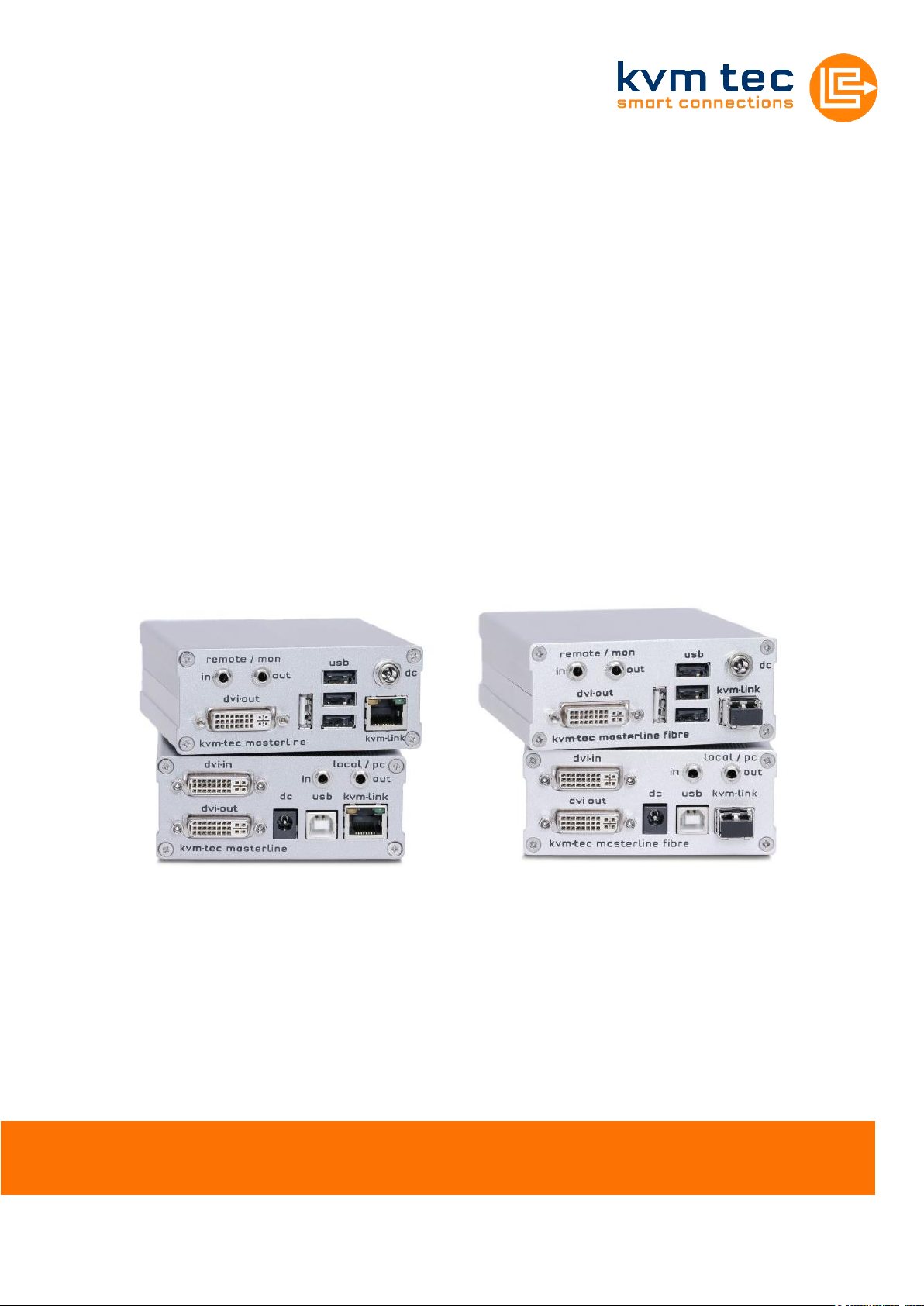
Masterline MVX/MVX-F KVM Extender
SWITCHING OPTION
Art.Nr: 6701
Masterline MVX1
Art.Nr: 6801
Masterline MVX1-F
www.kvm-tec.com

www.kvm-tec.com
Contents
Contents ....................................................................................................................................................... 2
1 Package contents .................................................................................................................................... 4
2 Specifications ........................................................................................................................................... 4
3 Installation ............................................................................................................................................... 4
4 Start up ..................................................................................................................................................... 6
4.1 Status Overview.................................................................................................................................................. 6
5 Menu / Settings ....................................................................................................................................... 8
5.1 Menu Item “U” – Update Flash FW .................................................................................................................... 8
5.2 Menu Item “M” – Option Overview ................................................................................................................... 8
5.3 Menu Item “O” – DDC Option ............................................................................................................................ 9
5.4 Menu Item “W” – Network Settings ................................................................................................................ 10
5.5 Menu Item “G” – Extender Settings ................................................................................................................. 10
5.5.1 Menu Item “V” – VGA parameters ........................................................................................................... 11
5.5.2 Menu Item “A” – Audio Input Gain .......................................................................................................... 12
5.5.3 Menu Item “R” – RS232 ............................................................................................................................ 12
5.5.4 Menu Item “S” – Show Last Image ........................................................................................................... 13
5.5.5 Menu Item “I” – Monitor Sync ................................................................................................................. 13
5.5.6 Menu Item “L” – Lock Menu ..................................................................................................................... 14
5.5.7 Menu Item “P” – Power Save ................................................................................................................... 14
5.5.8 Menu Item “K” – Keyboard Locale ........................................................................................................... 14
5.5.9 Menu Item “U” – USB Compatibility Mode .............................................................................................. 14
5.5.10 Menu Item “H” – Keyboard Shortcuts ................................................................................................ 15
5.6 Menu Item “L” – Switching List ........................................................................................................................ 15
5.7 Menu Item “Q” ................................................................................................................................................. 16
6 SWITCHING Menu Guide / Settings ................................................................................................... 17
6.1 Network Settings Item “V” – Master View (Device Configuration) .................................................................. 18
6.1.1 Master View Item “O” – Connections Overview ...................................................................................... 18
6.1.2 Master View Item “U” – User List ............................................................................................................. 19
6.1.3 Master View Item “C” – Console Extender List ........................................................................................ 21
6.1.4 Master View Item “P” – PC Extender List ................................................................................................. 22
6.1.5 Master View Item “M” – Multi-Head Configuration ................................................................................ 22
6.2 Network Settings Menu Item “M” – Network Mode ....................................................................................... 24
6.2.1 Network Settings Mode Item “R” – Reset Modes to Factory Default ...................................................... 24
6.2.2 Network Settings Mode Item “P” – Passwords Disabled ......................................................................... 24
6.2.3 Network Settings Mode Item “C” – Auto Connect ................................................................................... 25
2

www.kvm-tec.com
6.2.4 Network Settings Mode Item “V” – Private Connections ......................................................................... 25
6.2.5 Network Settings Mode Item “B” – User-PC Binding ............................................................................... 25
6.2.6 Network Settings Mode Item “D” – Disconnect on PC Power Down ....................................................... 26
6.2.7 Network Setting Mode Item „S“ - Video Sharing ..................................................................................... 26
6.3 Network Settings Item “T” – Set Timeout ........................................................................................................ 26
7 Switching between different computers .......................................................................................... 27
8 Multicast ................................................................................................................................................ 29
8.1 Video Sharing ................................................................................................................................................... 29
9 Mounting Options ................................................................................................................................ 30
9.1 Mounting Pads ................................................................................................................................................. 30
9.2 Rack Mounting Kit ............................................................................................................................................ 30
9.3 Under desk Mounting Kit ................................................................................................................................. 30
9.4 Din Rail Mounting Kit........................................................................................................................................ 30
9.5 Dual Mounting Kit ............................................................................................................................................ 30
10 Requirements ....................................................................................................................................... 31
11 Support ................................................................................................................................................. 32
12 Guidelines ............................................................................................................................................. 33
3
Package contents
www.kvm-tec.com
1 Package contents
1x MVX1 / PC 1x USB cable
1x MVX1 / Monitor 1x Quick Start Guide
2x Power supply 12V 1A 4x Mounting Pads
1x DVI-cable 4x Rubber Feet
2 Specifications
Max. ambient temperature: 45° Celsius
Dimensions: 98 x 41 x 106mm
Weight: 540g per Set
Power input: 5 W per device
Material: anodized aluminium
Power supply: 12V 1A external power supply
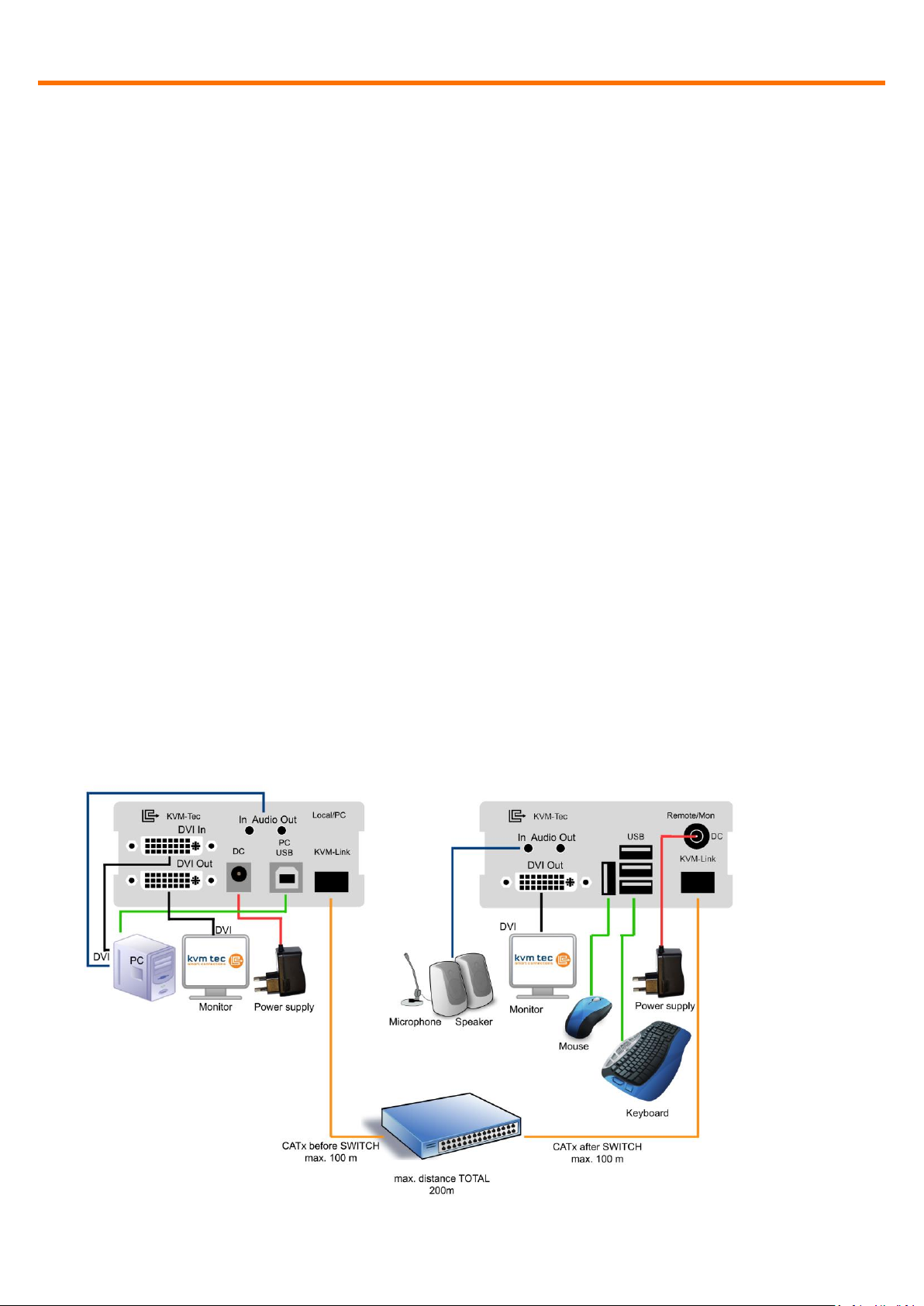
3 Installation
Connect all the cables from your PC as shown in the following diagram:
4
Installation
www.kvm-tec.com
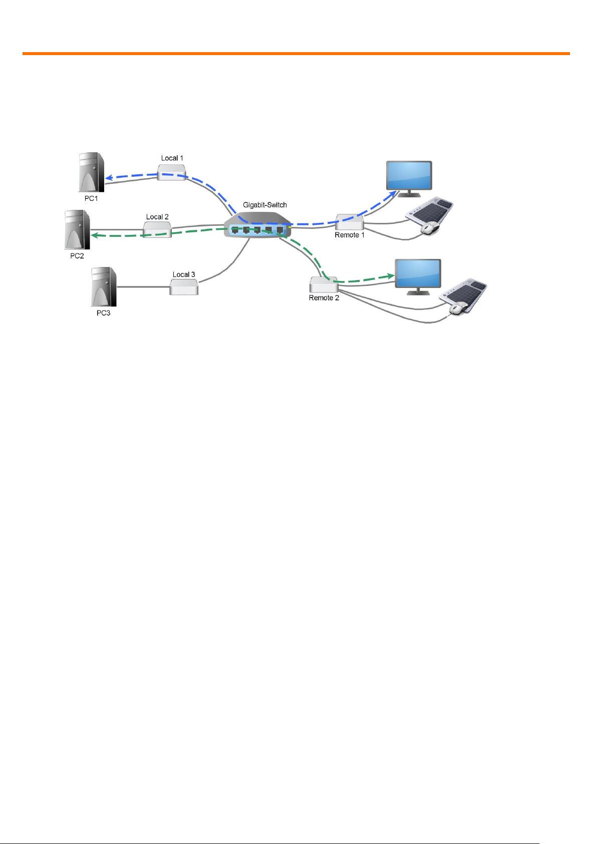
Connect the respective work stations (Remote Extenders) and computers (Local
Extenders) with the network switch.
Note the following:
The entire switching network system requires its own dedicated network. For
security reasons it cannot be integrated into an existing company network.
The network switch must fulfil the following specifications: 1 Gigabit Switch, with true
port to port transfer rates of 1 Gigabit/second
List of recommended network switches that have been tested with kvm-tec
extenders
TP-LINK TL-SG3216, 16port
TP-LINK TL-SG1016D, 16port
TP-LINK TLSG1048, 48port
DIGITUS DN80100,16port
LogiLink NS0050A, 5port
5
Start up
www.kvm-tec.com
Connected to <untitled>
DDC Opt remote monitor
Video Mode DVI
Resolution 1920x1080
USB Status High Speed
Options: Mem Switch
Rem FW Ver 4267
Local FW Ver 4267
[Link] [Conn] [Video] [USB]
Fig. 1
4 Start up
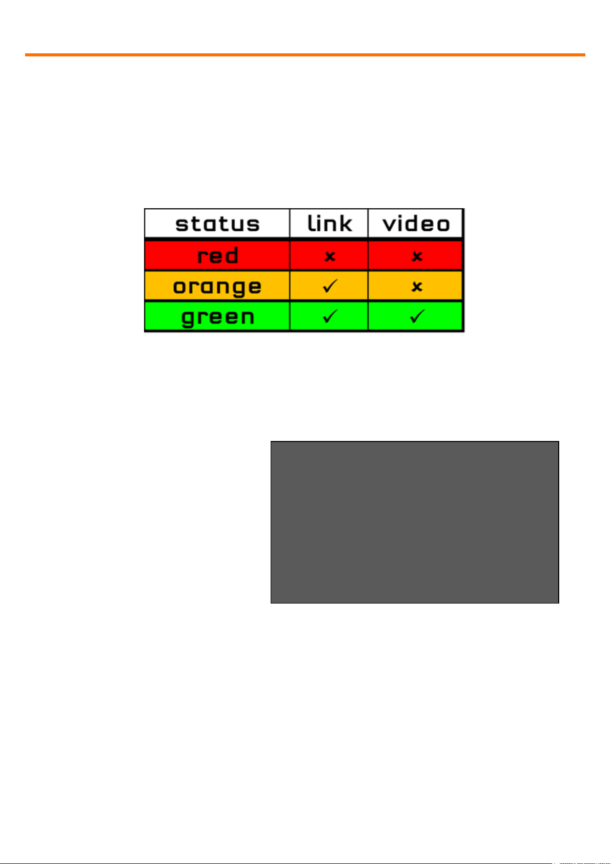
Switch on all devices. Both Extender units will start an automated initialisation
process, signified by a blinking red status light, this may take a few seconds.
When the status light turns green, all signals will be transmitted.
4.1 Status Overview
The Status Overview (Fig. 1)
provides the user with the most
important information about the
status of the extender in a single
screen. This will appear
automatically whenever no video
is been transmitted, but can also
be opened manually via the OSD
menu (see item 0). Of particular
interest is the row at the bottom,
showing the status of four subsystems as being either active (green) or inactive
(red).
6

www.kvm-tec.com
Link: Is there a physical link between this extender and another device via CATx
or fibre.
Conn: Has this console unit negotiated a connection with a PC unit.
Video: Is video currently being transmitted from the PC unit to the console unit.
USB: Has a transparent USB connection been established between the console
extender unit and the host PC.
7

Menu / Settings
www.kvm-tec.com
Menu
T = Status Overview
U = Update Flash FW
M = Option Overview
O = DDC Option (remote monitor)
W = Network Settings
G = Extender Settings
L = Switching List
Q = Exit
Remote (Con) FW Ver = 4267
Local (PC) FW Ver = 4267
Fig. 2
5 Menu / Settings
To enter the menu, use a keyboard connected to the remote Extender and press
the “<Scroll Lock>” key five times in quick succession.
The menu will be displayed (Fig. 2). Sub-menus are accessed by pressing the
appropriate key. The currently installed firmware version is displayed below the
menu.
5.1 Menu Item “U” – Update Flash FW
Used to perform a firmware update. The latest version of the firmware can be
downloaded from www.kvm-tec.com. Each update file is accompanied by a
detailed description of the update process.
5.2 Menu Item “M” – Option Overview
Displays the extender’s activated options. The status is indicated by the colours
green (activated), and red (not activated).
If the memory option on the extender is activated this can be enable or disabled
at any point in this menu.
In order to active options complete the following steps:
8

Menu / Settings
www.kvm-tec.com
DDC Options
+--------------------------------------+
0 = remote monitor
1 = local monitor
2 = last DDC fixed
4 = FIX 1024x768
5 = FIX 1280x1024
6 = FIX 1680x1050
7 = FIX 1920x1080
8 = FIX 1920x1200
Options Overview
[USB Memory] – Enabled
(1 – enable, 0 – disable)
[RS232] [VGA]
[Sound] [Switching]
Device ID: 123456f7
Send ID to distributor to unlock
options.
Press M to enter code.
Fig. 3
Fig. 4
The menu displays the ID number
of the device (see Fig. 3). Please
contact your distributor and
advice him of the ID number of
your device. They can then send
you the activation code for the
desired option. You can enter this
activation code by pressing the
“M” key. This will not alter other
options that have already been
activated. Return to the main
menu with “esc”.
5.3 Menu Item “O” – DDC Option
In this menu you can define DDC information is used by the PC .Pressing “0“
specifies that the DDC information from the monitor attached to the remote
Extender should be used. Pressing “1“ specifies that the DDC information from
the monitor attached to the local Extender should be used.
Pressing “2“ saves the current DDC information allowing the system to continue
on the same after the Extender has been restarted.
Using the keys “4“ through “8“ sets the system to use a predefined resolution
which is saved (Fig. 4).
To return to the main menu press “ESC“.
9

Menu / Settings
www.kvm-tec.com
Extender Settings
+--------------------------------------+
L = Local Settings
R = Remote Settings
Q = Return to Main Menu
Fig. 5
Local Settings
+--------------------------------------+
V = VGA parameters
U = USB Compatibility Mode (disabled)
Q = Return to Main Menu
Fig. 6
5.4 Menu Item “W” – Network Settings
The menu includes the preferences and settings for the switching option.
See item 7.
5.5 Menu Item “G” – Extender Settings
This menu presents a range of
further preferences. They are
divided in to two sub-menus
depending on whether the setting
is stored on the Local (PC) unit or
Remote (console) unit.
10

Menu / Settings
www.kvm-tec.com
Remote Settings
+--------------------------------------+
A = Audio Input Gain (5)
R = RS232 Baudrate (up to 9600)
S = Show Last Image (disabled)
I = Monitor Sync (disabled)
L = Lock Menu (disabled)
P = Power Save (enabled)
K = Keyboard Locale (EN)
O = Keyboard Fallback Mode (0)
H = Keyboard Shortcuts
Q = Return to Main Menu
Fig. 7
5.5.1 Menu Item “V” – VGA parameters
This is where VGA preferences can be set and optimised.
By pressing the “F1” and “F4” keys the display area can be moved up and down.
“F2” and “F3” shift the display area left and right.
By using the “F5” and “F6” keys the display area can be reduced or enlarged to fit
the display area of the monitor.
Press the “<space bar>” to change the rate of change of the above settings. By
repeatedly pressing the “space bar“ this is set back to 1.
Use the “M” button to switch the video mode between:
Auto – the mode is automatically detected and set by the Extender
DVI – only DVI input is detected
VGA – only VGA input is detected
For automatic adjustment and positioning of the image area, press “K”.
Press “I” to reset parameters to default values.
To save the settings and exit the menu press “S” – for an exit without saving
press “Q”.
11
 Loading...