

Page 1

TracVision M7 Installation Guide
TracVision M7
Switchplate Configuration
Page 2

TracVision M7 Installation Guide
Switchplate Configuration
These instructions explain how to install the TracVision M7 satellite TV antenna system on a
vessel. Complete instructions on how to use the system are provided in the User’s Guide.
Installation Steps
1. Inspect Parts and Get Tools, 3
2. Plan the Antenna Installation, 4
3. Plan the Switchplate Installation, 5
4. Prepare the Antenna Site, 6
5. Remove the Restraint, 7
6. Wire the Antenna, 8
7. Mount the Antenna, 9
8. Wire the Switchplate, 10
9. Wire the Receiver(s), 11
10. Connect Power, 12
11. Mount the Switchplate, 13
12. Enter Your Latitude & Longitude, 14
13. Select Satellites, 16
14. Set the LNB Skew Angle (Linear only), 17
15. Educate the Customer, 18
Who Should Install the System?
To ensure a safe and effective installation, KVH recommends that a KVH-authorized marine
technician install the TracVision antenna. KVH-authorized technicians have the tools and
electronics expertise necessary to install the system. To find a technician near you, visit
www.kvh.com/wheretogetservice.
Linear vs. Circular Systems
The installation process differs slightly depending on the type of LNB (low noise block) that is
installed in the antenna (linear or circular). These differences are noted throughout this manual.
Appendix B on page 23 notes the type of LNB required for each region and satellite.
Technical Support
If you need technical assistance, please contact KVH Technical Support:
North/South America, Australia:
Phone: +1 401 847-3327
E-mail: techs@kvh.com
KVH, TracVision, and the unique light-colored dome with contrasting baseplate are registered trademarks of KVH Industries, Inc.
All other trademarks are property of their respective companies. The information in this document is subject to change without notice.
No company shall be liable for errors contained herein. © 2007 KVH Industries, Inc., All rights reserved. 54-0417 Rev. A
Europe, Middle East, Asia:
Phone: +45 45 160 180
E-mail: support@kvh.dk
1
Page 3
1
Inspect Parts and Get Tools
Before you begin, follow these steps to make sure
you have everything you need to complete the
installation.
a. Unpack the box and ensure it contains
everything shown on the Kitpack Contents
List. Save the packaging for future use.
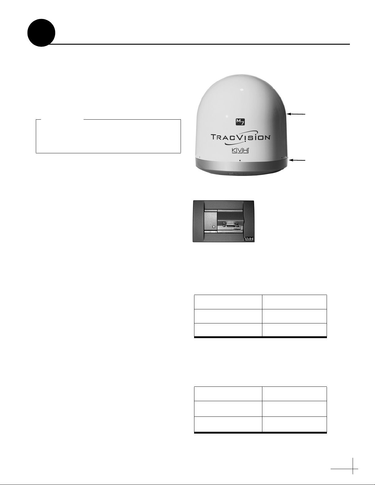
IMPORTANT!
Always lift the antenna by the baseplate and
never by the radome or any portion of the
internal antenna assembly (see Figure 1).
b. Carefully examine all of the supplied parts to
ensure nothing was damaged in shipment.
c. Gather all of the tools and materials listed
below. You will need these items to complete
the installation.
• Flat-head and Phillips-head screwdrivers
• Electric drill and 1/2" (13 mm), 5/32"
(4 mm), and 3/32" (2.25 mm) drill bits
Figure 1: TracVision M7 System Components
Antenna
Radome
Baseplate
Switchplate
• 3" (80 mm) hole saw
• Socket wrenches
• 7/16" open-end wrench
• Light hammer and center punch
• Adhesive tape and scriber or pencil
• Wire strippers and terminal lug crimper
• RG-6 or RG-11 RF coax cable(s) with
Snap-N-Seal® F-connectors (see Figure 2);
see Step 6a on page 8 to determine the
number of cables required
• Connector installation tool (Augat IT1000
- KVH part #19-0242)
• Power cable (see Figure 3)
• Satellite TV receiver and TV
• Windows® laptop PC with Windows
HyperTerminal or KVH Flash Update
Wizard installed
Figure 2: RF Cable Guidelines
Cable Length Use Cable Type
<= 75 ft (23 m) RG-6
> 75 ft (23 m) RG-11
Figure 3: Power Cable Guidelines
Cable Length Use Cable Gauge
< 40 ft (12 m)
40-70 ft (12-21 m)
14AWG (2.5mm
12AWG (4mm
2
)
2
)
3
Page 4
2
Plan the Antenna Installation
Before you begin, consider the following antenna
installation guidelines:
• Minimize blockage. The antenna requires a
clear view of the sky to receive satellite TV
(see Figure 4). The fewer obstructions, the
better the system will perform.
• Make sure the mounting surface is wide
enough to accommodate the antenna’s base
(see Figure 5). Also make sure it is flat, level,
strong enough to support the antenna’s
weight (55 lbs, 25 kg), and rigid enough to
withstand vibration.
• Select a location that is as close as possible to
the intersection of the vessel’s fore-and-aft
centerline and midships.
• Do not mount the antenna at the same level
as the radar because the radar’s energy might
overload the antenna. Ideally, you should
mount the antenna 4 ft (1.2 m) above and 4 ft
(1.2 m) away from the radar.
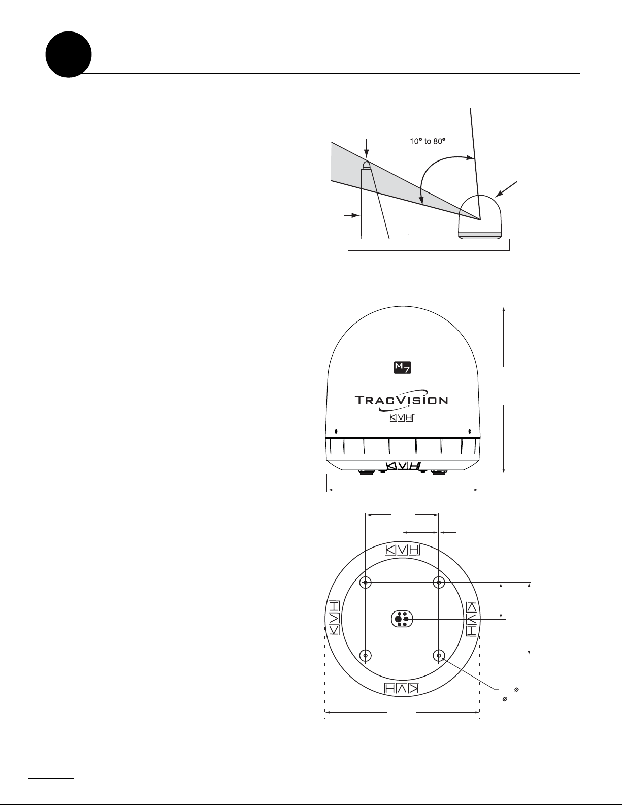
Figure 4: Blockage from Obstruction
Blocked!
Look Angle
Mast
Vessel Platform
Figure 5: Antenna Dimensions
TracVision Antenna
Side View
(69.5 cm)
27.36"
26.2"
(66.5 cm)
12"
(30.5 cm)
6"
(15.2 cm)
Bottom View
6"
(15.2 cm)
12"
(30.5 cm)
4 x 1/2"
26.2"
(66.5 cm)
4
( 13 mm)
Page 5
3
Plan the Switchplate Installation
Before you begin, consider the following
switchplate installation guidelines:
• Select a switchplate mounting location in a
dry, well-ventilated area belowdecks away
from any heat sources or salt spray.
• Be sure to leave enough room at the
switchplate’s rear panel for connecting the
cables (see Figure 6 for switchplate
dimensions).
• Since the supplied data cable is 50 ft (15 m)
long, the switchplate must be located within
50 ft (15 m) of the antenna.
Prepare the Switchplate Mounting Site
Once you have identified a suitable switchplate
mounting site, follow these steps to prepare the
site for installation.
a. Using the switchplate mounting template
provided at the end of this manual, mark and
cut out a hole in the mounting surface to
accommodate the switchplate (see Figure 7).
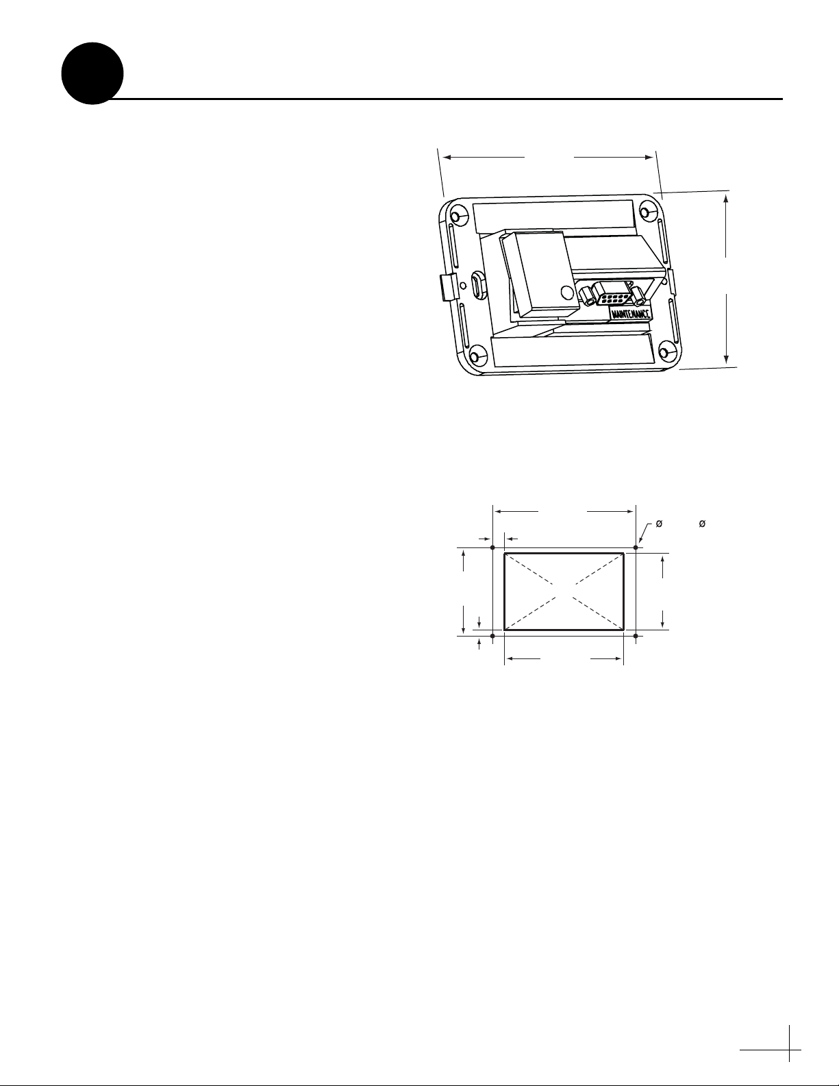
Figure 6: Switchplate Dimensions
4.39"
(111.5 mm)
Figure 7: Switchplate Mounting Holes Layout
3.82"
(97 mm)
.32" (8 mm)
3/32" ( 2.25 mm)
Mounting Hole (x4)
2.96"
(75.2 mm)
b. Using the same template, mark the locations
for the four switchplate mounting holes.
c. Drill a 3/32" (2.25 mm) hole at the four
mounting hole locations. Later, you will
mount the switchplate using four #6 screws.
2.36"
(60 mm)
.16" (4 mm)
Panel Cutout
3.19"
(81 mm)
2.05"
(52 mm)
5
Page 6
4
Prepare the Antenna Site
Once you have identified a suitable antenna
mounting site, according to the guidelines
provided in Step 2, follow these steps to drill the
mounting holes and cable access hole to prepare
the site for installation.
a. Unfold the antenna mounting template
(supplied in the Customer Welcome Kit) and
place it onto the mounting surface. Make sure
the “FWD” (forward) arrow points toward
the bow and is parallel to the vessel’s
centerline (see Figure 8).
NOTE: You don’t need to mount the antenna
exactly on the vessel’s centerline, but the
antenna’s forward arrow must be parallel to it.
b. Use the template to mark the locations for the
four mounting holes and cable access hole on
the mounting surface.
c. Drill a 1/2" (13 mm) hole at the four
mounting hole locations you marked in
Step 4b. Later, you will insert four 3/8"-16
bolts through these holes to secure the
antenna to the mounting surface.
d. Cut out the 3" (80 mm) cable access hole in
the location you marked in Step 4b. Smooth
the edges of the hole to protect the cables.
Later, you will route the data, power, and RF
cables through this hole and into the vessel.
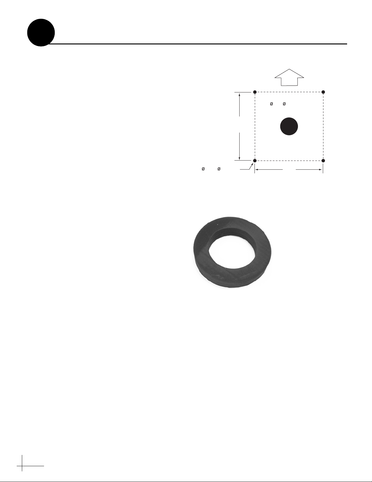
Figure 8: Antenna Mounting Holes Layout
FWD
3" ( 80 mm)
Cable Access Hole
12"
(305 mm)
1/2" ( 13 mm)
Mounting Hole (x4)
Figure 9: Foam Seal
Align with
Cable Access
Hole
(305 mm)
12"
e. Clean and dry the antenna mounting surface.
f. Peel off the paper backing from the supplied
foam seal to expose the adhesive. Then press
the foam seal down firmly onto the mounting
surface, ensuring the hole in the foam seal
aligns with the cable access hole in the
mounting surface (see Figure 9).
6
Page 7
5
Remove the Restraint
Inside the antenna, a foam block prevents the
antenna assembly from moving during
shipment. Follow these steps to remove this
shipping restraint.
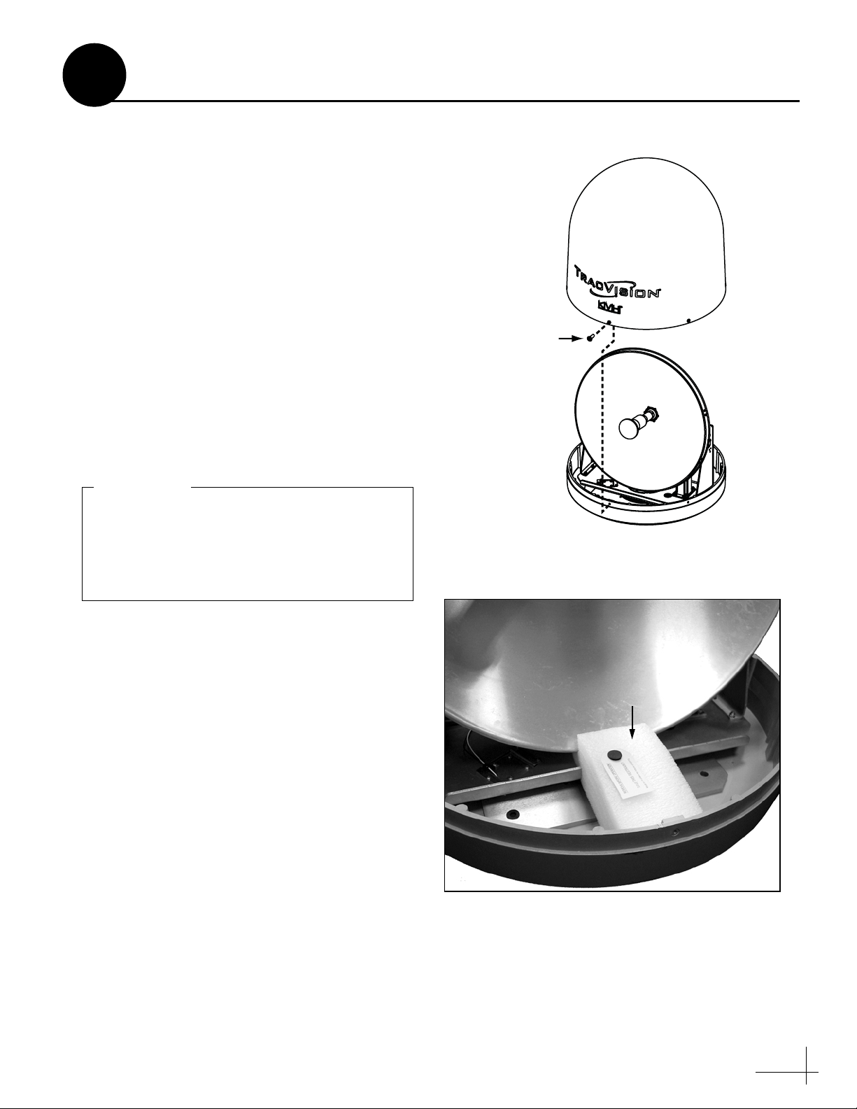
a. Remove the six #10-32 Phillips screws
securing the radome to the baseplate (see
Figure 10). Carefully lift the radome straight
up until clear of the antenna assembly and set
it aside in a safe place.
TIP: If you keep the radome topside, secure it with
a lanyard to prevent it from falling overboard.
b. Remove the foam block that is wedged
beneath the antenna’s reflector (see
Figure 11). Save this restraint for future use;
the customer will need to reinstall it if he/she
needs to relocate or reship the antenna.
IMPORTANT!
Once you have removed the restraint, handle
the antenna very carefully. With the restraint
removed, the internal antenna assembly
rotates freely and, if not handled properly,
can damage the limit switch.
Figure 10: Removing the Radome
#10-32 Screw (x6)
Figure 11: Foam Block Shipping Restraint
Shipping Restraint
7
Page 8
6
Wire the Antenna
Follow these steps to connect the data, power,
and RF cables to the antenna.
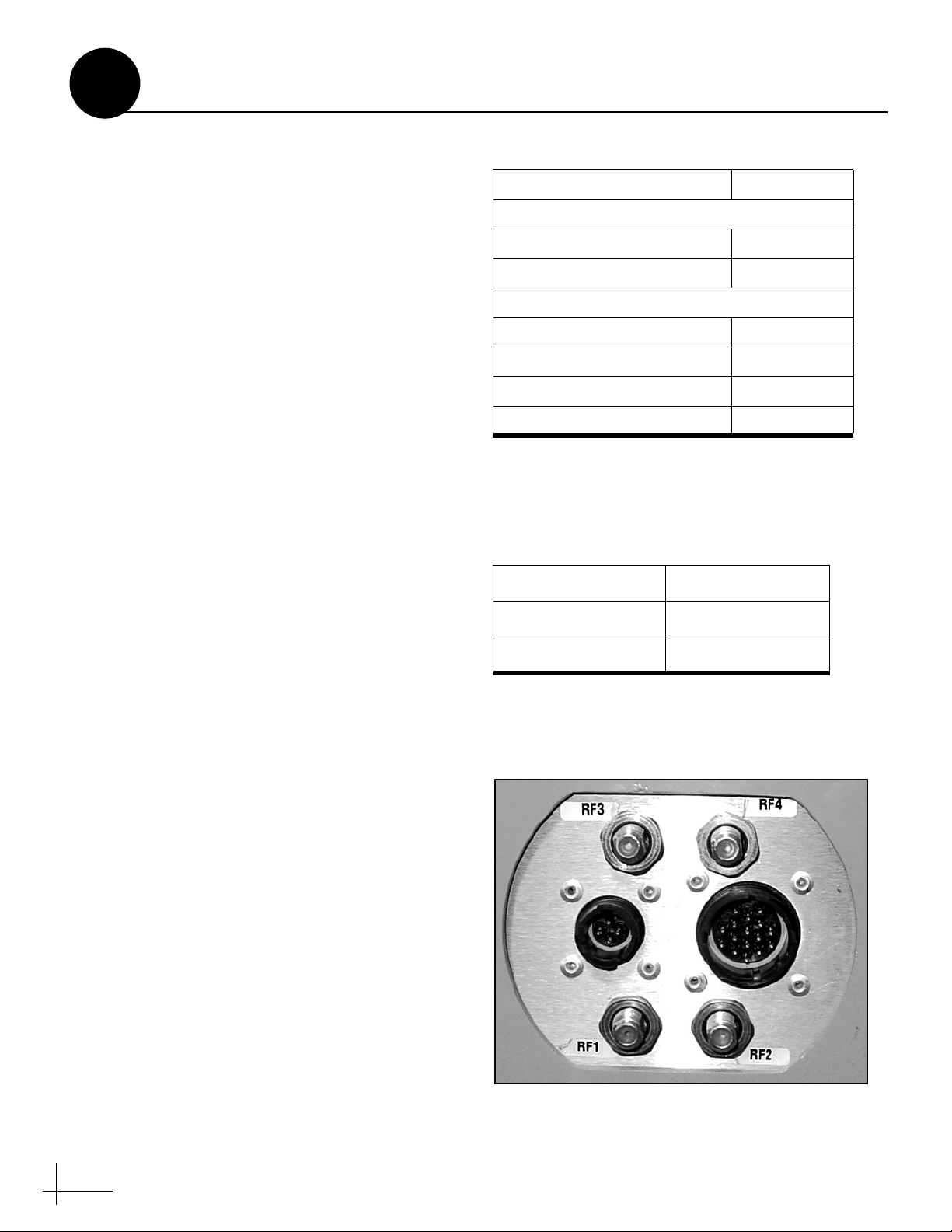
a. First determine the number of RF coax cables
required for your particular installation (see
Figure 12). (See Figure 13 to determine the
type of cable required.)
b. Route the data, power, and RF cables
belowdecks through the 3" (80 mm) cable
access hole. Leave an adequate service loop,
approximately 8" (20 cm) of slack, in the
cables for easy serviceability. Later, you will
connect the data and power cables to the
switchplate and the RF cable(s) to the
receiver(s).
c. Connect the data cable to the “Data” jack on
the bottom of the antenna (see Figure 14).
Hand-tighten until the connector locks in
place; do not use excessive force.
d. Connect the power cable to the “Power” jack
on the bottom of the antenna. Hand-tighten
until the connector locks in place; do not use
excessive force.
Figure 12: Number of RF Coax Cables Required
Connecting to: # RF Cables
System with Dual LNB
1 receiver 1
2 or more receivers 2*
System with Quad LNB (Europe Only)
1 receiver 1
2 receivers 2
3 receivers 3
4 or more receivers 4**
* Multiswitch required for 3 or more receivers.
** Multiswitch required for 5 or more receivers.
See Appendix A on page 21 for details.
Figure 13: RF Cable Guidelines
Cable Length Use Cable Type
<= 75 ft (23 m) RG-6
e. Connect the RF coax cable(s) to the antenna.
If you need to connect just one RF cable,
connect the cable to the “RF1” jack on the
bottom of the antenna. Hand-tighten, then
tighten with a 7/16" wrench for 1/4 turn to
ensure an electrical and weather-proof
connection. Connect any additional RF coax
cables to the antenna’s RF2, RF3, and RF4
jacks, in that order.
TIP: If you connect two or more RF cables, label
both ends of each cable to match the connector.
This will make it easier to identify the cables later.
> 75 ft (23 m) RG-11
Figure 14: Connectors on Bottom of Antenna
DataPower
8
Page 9
7
Mount the Antenna
Follow these steps to mount the antenna to the
mounting surface.
a. Place the antenna baseplate over the holes
drilled in the mounting surface.
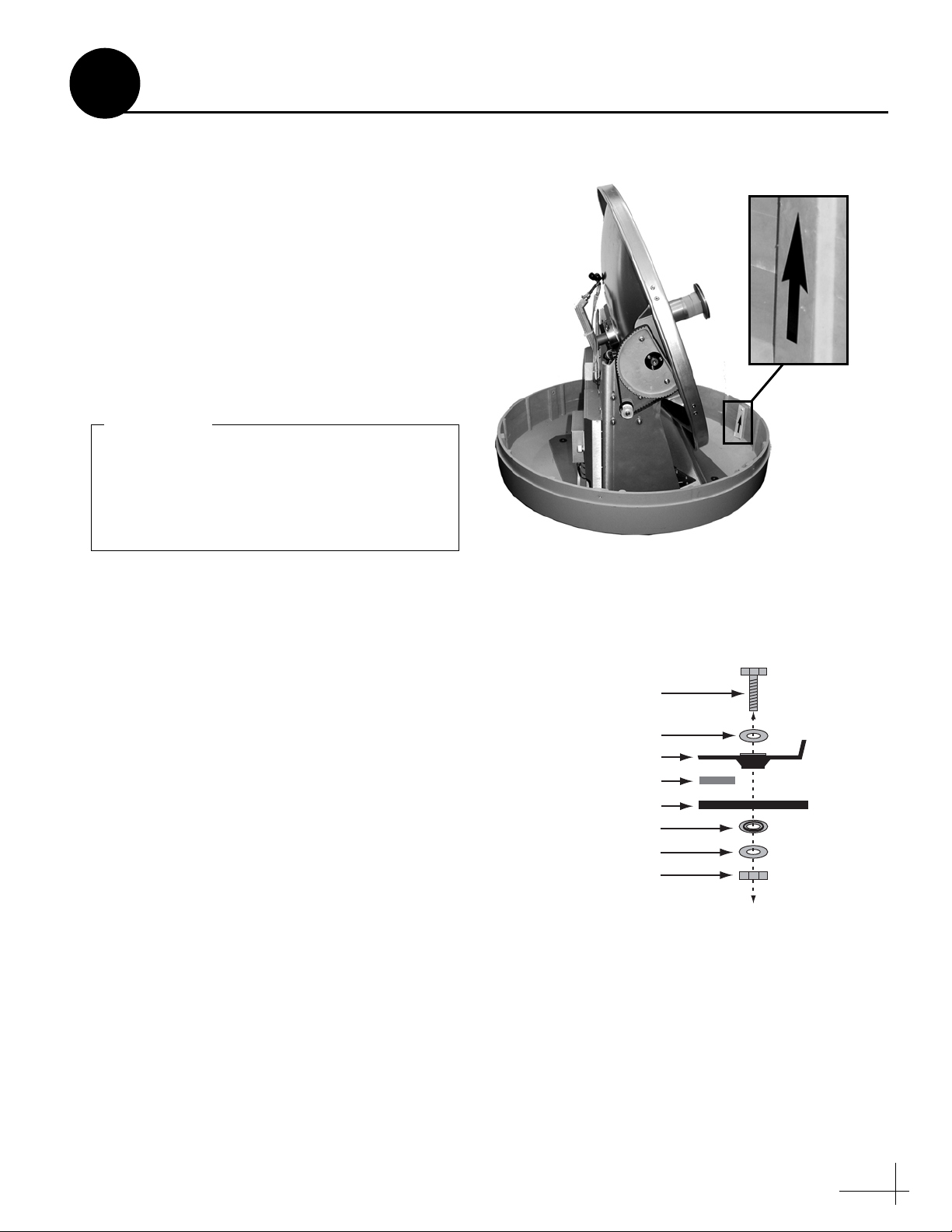
b. Make sure the forward arrow inside the
baseplate points toward the bow and is
parallel to the vessel’s centerline (see
Figure 15).
c. Make sure the four holes in the baseplate line
up with the four holes in the mounting
surface.
IMPORTANT!
You will need to rotate the antenna assembly
by hand to see all four mounting holes. Rotate
the antenna assembly slowly. If it hits a
mechanical stop with excessive force, the
limit switch might become damaged.
d. At each of the four baseplate mounting holes,
place a 3/8" flat washer on a 3/8"-16 bolt and
insert the bolt into the hole from above (see
Figure 16).
Figure 15: Forward Arrow in Antenna Baseplate
Figure 16: Mounting the Antenna (Side View)
e. Secure each mounting bolt to the mounting
surface using a 3/8" shoulder washer, a
3/8" flat washer, and a 3/8"-16 lock nut from
below. Tighten all four bolts until the four
rubber feet are bottomed against the
mounting surface and the foam seal is fully
compressed.
TIP: If you are installing a linear system, you may
wish to keep the radome off for now. Later, you will
need to adjust the skew angle of the antenna’s LNB.
f. Reinstall the radome onto the antenna. Secure
in place with the six #10-32 screws you
removed in Step 5a.
g. Install a protective plastic screw cap
(supplied in the kitpack) over each radome
screw.
3/8"-16 Bolt (x4)
3/8" Flat Washer (x4)
Antenna Base
Foam Seal
Mounting Surface
3/8" Shoulder Washer (x4)
3/8" Flat Washer (x4)
3/8"-16 Lock Nut (x4)
9
Page 10
8
Wire the Switchplate
Follow these steps to connect the switchplate to
the antenna.
NOTE: System wiring diagrams are provided in
Appendix D on page 27.
a. First dress the data and power cables from
the antenna. Strip back the insulation of each
wire approximately 1/4" (6 mm) and gently
twist each wire to ensure a good electrical
connection.
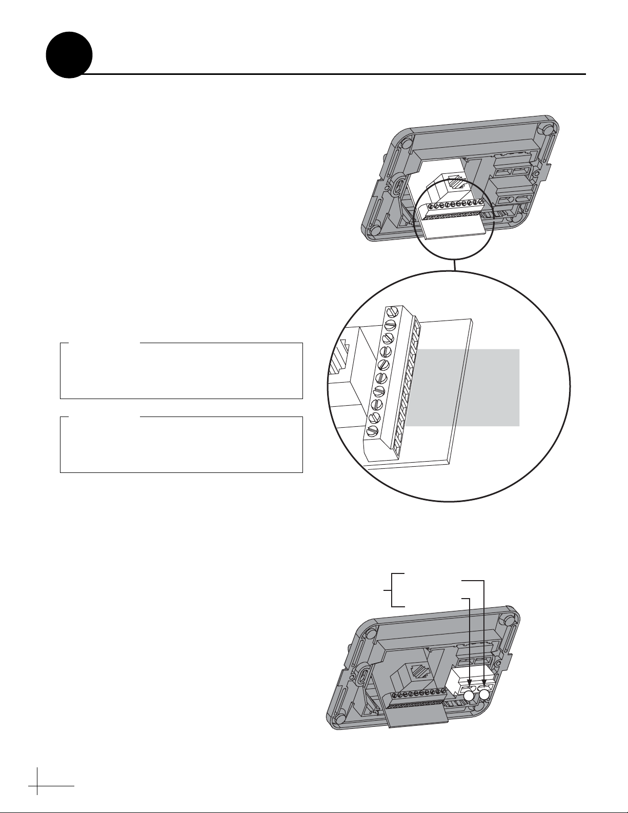
b. Connect the data cable from the antenna to
the terminal board on the back of the
switchplate (see Figure 17). Be sure to match
the wire colors with the terminal board label.
Tighten the terminal screws to secure all
wires in place.
IMPORTANT!
The diagram refers to wires by body color/
stripe color. For example, “Blue/White”
means the blue wire with the white stripe.
IMPORTANT!
Do not connect the data cable’s drain wire
(shield) to anything. You can simply snip it
from the cable.
Figure 17: Switchplate Wiring - Antenna Data Cable
BLU/WHT Not Used
WHT/BLU Not Used
BRN/WHT PC GND
WHT/BRN PC TXD
ORG/WHT PC RXD
WHT/ORG RF GND
GRY/WHT RF RXD
WHT/GRY RF TXD
GRN/WHT Not Used
WHT/GRN Not Used
Data Cable
to Antenna
c. Connect the power cable from the antenna to
the switchplate’s power output terminals (see
Figure 18).
10
Figure 18: Switchplate Wiring - Antenna Power Cable
To Antenna
Ground (Black)
+12 VDC (Red)
–
+
Page 11

SATELLITE IN
SATELLITE IN
9
Wire the Receiver(s)
In Step 6, you routed the RF coax cable(s) from
the antenna, through the cable access hole, and
into the vessel. Follow these steps to connect the
RF coax cable(s) to the customer’s satellite TV
receiver(s).
IMPORTANT!
If you wish to connect three or more receivers
to the antenna, see Appendix A on page 21.
a. If you are connecting two receivers to the
TracVision system, decide which receiver
will be the primary receiver. The primary
receiver controls satellite selection.
NOTE: The secondary receiver will only be able to
select a channel carried on the satellite that is
currently selected on the primary receiver.
b. Connect the RF1 cable from the antenna to
the “Satellite In” jack on the primary receiver
(see Figure 19).
c. If you are connecting two receivers, connect
the RF2 cable from the antenna to the
“Satellite In” jack on the secondary receiver.
Figure 19: Wiring the Receivers to the Antenna
Antenna
Primary Receiver
TV ANT/CABLE IN
RF1
SATELLITE IN
RL
OUT TO TV
AUDIO VIDEO S-VIDEO PHONE JACK
This receiver controls
satellite selection
Secondary Receiver - Optional
TV ANT/CABLE IN
RF2
SATELLITE IN
RL
OUT TO TV
AUDIO VIDEO S-VIDEO PHONE JACK
IMPORTANT!
Be sure all receivers are grounded. If the
receiver has a 2-prong power plug, run a
ground wire from the receiver’s chassis to a
suitable ground point. If a potential exists
between AC and DC grounds, connect the
wire to the switchplate’s DC return instead.
d. Connect the receiver(s) to the customer’s
television(s). Follow the instructions in the
receiver’s manual.
11
Page 12

10
Connect Power
Follow these steps to connect power. The
switchplate supplies power to the antenna.
a. Before you begin, disconnect vessel power.
CAUTION
For your own safety, disconnect vessel power
and make sure the circuit is dead before you
connect any power wires.
b. Connect a power cable to 12 VDC vessel
power (for cable specifications, see Figure 3
on page 3).
IMPORTANT!
Power supplied to the antenna must not fall
below 11 VDC or exceed 16 VDC.
c. Connect your vessel power wires to the
power (+) and ground (-) input terminals on
the switchplate (see Figure 20).
Figure 20: Switchplate Wiring - Vessel Power Cable
Vessel Power
Ground
11-16 VDC
–
+
12
Page 13

11
Mount the Switchplate
In Step 3, you identified a suitable mounting
location for the switchplate and cut out the
mounting hole in the mounting surface. Now
follow these steps to mount the switchplate.
a. Fit the switchplate assembly into the
mounting hole until it is flush with the
mounting surface.
b. Drill four 5/32" (4 mm) holes in the
countersunk settings in the switchplate’s
support frame (see Figure 21).
c. Secure the support frame and switchplate
assembly to the mounting surface using four
#6 screws.
d. Snap the front cover onto the switchplate to
conceal the mounting screws and support
frame.
Figure 21: Mounting the Switchplate
Front Cover
Switchplate
Mounting Surface
5/32" ( 4 mm)
Mounting Hole (x4)
#6 Screw (x4)
13
Page 14

12
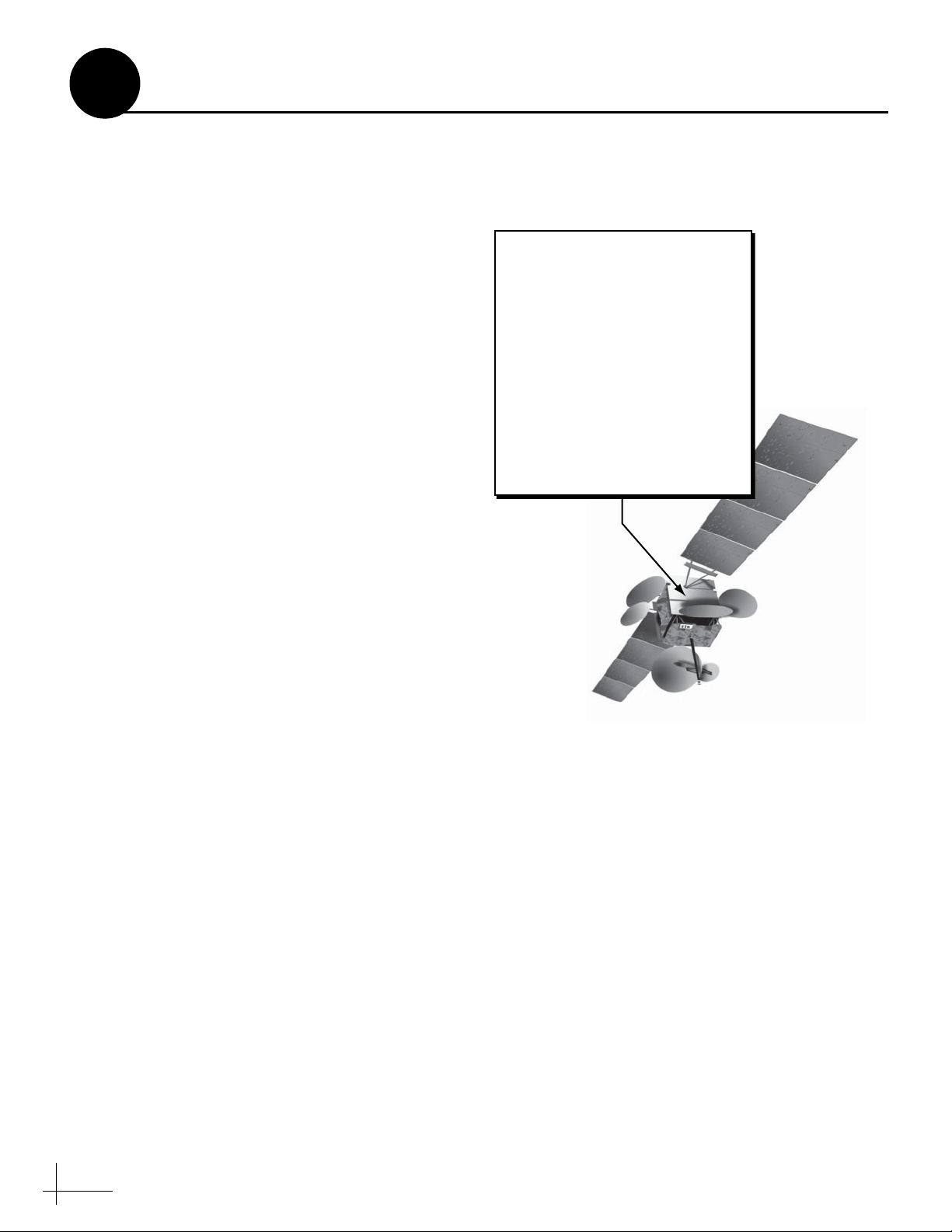
Enter Your Latitude & Longitude
Follow these steps to enter your vessel’s latitude
and longitude into the antenna.
NOTE: The antenna will use your position
information to speed up satellite acquisition. If the
antenna knows where you are, it knows where it
should start looking for the satellite (see Figure 22). In
addition, for a linear system, the antenna will use
your position information to calculate the correct LNB
skew angle.
Connect a Laptop to the Antenna
To enter data into the antenna, you first need to
connect a Windows® laptop computer to the
TracVision system and start Windows
HyperTerminal.
TIP: If you are a KVH-authorized technician, you can
use the KVH Flash Update Wizard instead of
HyperTerminal. Enter commands in the wizard’s
“Antenna Comms” window.
Figure 22: Direction to Satellite Depends on Your Location
Figure 23: Switchplate Front Panel
a. Using a straight PC serial data cable, connect
your laptop to the DB9 Maintenance port on
the front of the switchplate (see Figure 23).
NOTE: If your computer does not have a DB9 serial
COM port, you can use the USB-to-RS232 adapter
manufactured by IOGear (IOGear part number
GUC232A) or Belkin (Belkin part number F5U109).
b. Open Windows HyperTerminal and establish
the following settings for your COM port (see
Figure 24):
• Bits per second: 9600
• Data bits: 8
•Parity: None
• Stop bits: 1
•Flow control: None
TIP: To view characters on the screen as you type, set
up HyperTerminal to echo typed characters. Select
“Properties” from the File menu; select “ASCII
Setup” at the Settings tab; then select “Echo typed
characters locally” at the ASCII Setup window.
Maintenance Port
ON
OFF
Figure 24: HyperTerminal Settings
Maintenance Port
14
Page 15

12
Continued...
c. Ensure the antenna has a clear, unobstructed
view of the sky.
d. Apply power to the satellite TV receiver(s)
and the switchplate (see Figure 23 on page
14). Wait two minutes for system startup.
e. Data should now be scrolling in your
HyperTerminal window (see Figure 25). If no
data appears, check your connections and
make sure you’re using the right COM port.
Enter Your Latitude and Longitude
To enter your position information into the
antenna, enter the following commands via
Windows HyperTerminal or KVH Flash Update
Wizard:
a. Type HALT then press Enter.
b. Type DEBUGON then press Enter.
c. Type the following command then press
Enter. Italics indicate a variable.
Figure 25: Antenna Data Scrolling in Window
GPS,XX,A,YYY,B
XX = Latitude (0 - 90)
A = S (South) or N (North)
YYY = Longitude (0-180)
B = E (East) or W (West)
NOTE: Do not enter decimals. Simply round your
latitude and longitude to the nearest whole numbers.
EXAMPLE
Entering a vessel position of 57°N, 22°E:
HALT
DEBUGON
GPS,57,N,22,E
15
Page 16

13
Select Satellites
Follow these steps to set up the system for the
desired pair of satellites.
IMPORTANT!
The antenna is programmed at the factory for
the following default satellite pair:
Circular: DSS_101 & DSS_119 (DIRECTV)
Linear: ASTRA & HOTBIRD
If these are the customer’s desired satellites,
you may skip this step.
Enter the following commands via Windows
HyperTerminal or KVH Flash Update Wizard:
a. Type HALT then press Enter.
b. Type DEBUGON then press Enter.
c. Type the following command then press
Enter. Italics indicate a variable.
SATINSTALL,SatelliteA,SatelliteB
SatelliteA = Name of 1st desired satellite
SatelliteB = Name of 2nd desired satellite
See Appendix B on page 23 for a list of all
available satellites. Be sure to enter the
satellite names as they appear in the library.
Figure 26: Technician Programming the Antenna
EXAMPLE
Programming Astra2S and Thor satellites:
HALT
DEBUGON
SATINSTALL,ASTRA2S,THOR
@L,A
ZAP
NOTE: If you don’t find the satellite you want,
you can set up a user-defined satellite (USER 1 or
USER 2). See Appendix C on page 24.
d. Type @L,A then press Enter.
e. Type ZAP then press Enter. The antenna
restarts. Wait two minutes for system startup.
f. (Linear only) Set up the receiver(s) for the
same satellites, and in the same order, that
you set them up in the antenna:
Antenna Receiver DiSEqC
Sat. A Alternative 1 or A DiSEqC 1
Sat. B Alternative 2 or B DiSEqC 2
16
Page 17

14
Set the LNB Skew Angle (Linear only)
Follow these steps to set the antenna’s linear LNB
to the correct skew angle for your selected
satellite and vessel position.
a. Using HyperTerminal or KVH Flash Update
Wizard, type SKEWANGLE then press
Enter. Note the reported skew angle.
TIP: The SKEWANGLE command provides the
correct skew angle for the currently selected satellite
only. If a pair of satellites is installed, you might wish
to set an average skew instead. To find the average
skew, select the second satellite then enter the
SKEWANGLE command again to get the second
satellite’s skew angle. Add the two skew angle
numbers together and divide by two to get the average.
b. Turn off and unplug the receiver(s) and
disconnect antenna power at the switchplate.
Figure 27: Wing Screws Securing the LNB to the Reflector
Reflector
Wing
Screws
LNB
CAUTION
Disconnect power from the antenna and the
receivers before you adjust the LNB. The
antenna’s moving parts can cause injury.
c. Remove the antenna’s radome, if you
installed it earlier in Step 7f.
d. Locate the LNB on the back of the antenna’s
reflector (see Figure 27).
e. Loosen the two wing screws on the LNB
choke feed. These wing screws secure the
LNB in place.
f. Adjust the LNB clockwise or counter-
clockwise until the skew arrow on the LNB
points to the skew angle that you noted in
Step 14a (see Figure 28).
IMPORTANT!
Be sure to keep the LNB fully inserted into the
choke feed to ensure optimum performance.
g. Tighten the wing screws to secure the LNB.
Figure 28: LNB Skew Angle Adjustment
LNB
S
K
W
E
90
85
80
70
75
60
65
55
Negative
Skews
50
40
45
30
35
25
20
10
15
5
0˚ Skew
0
20
10
15
5
60
0
5
40
0
3
45
35
25
Positive
Skews
Choke Feed
90
85
80
75
70
65
5
5
h. Reinstall the radome (as explained in
Steps 7f-g on page 9).
17
Page 18

15
Educate the Customer
The installation process is complete!
Before you depart the vessel, test the system to
verify the antenna works properly. Then give the
Customer Welcome Kit to the customer and
explain how to use the system. Also be sure the
customer understands the following:
• Keep the radome installed on the antenna at
all times. The radome protects the antenna’s
moving parts from wind, rain, and debris.
WARNING
It is dangerous to watch TV while piloting a
vessel. The TracVision system is intended as
a passenger entertainment product only.
• The antenna must have a clear view of the
sky to receive satellite TV. Common causes of
blockage include trees, buildings, bridges,
and onboard equipment (see Figure 29).
Figure 29: Example of Satellite Blockage
TracVision
• Heavy rain or snow may temporarily
interrupt reception.
• Clean the antenna regularly. Dirt buildup on
the radome can affect reception.
• The vessel must be located within the
selected satellite’s coverage area to receive its
satellite TV signals. To view satellite coverage
maps, visit www.kvh.com/footprint.
• Please register the system with KVH. The
registration process is quick, easy, online, and
ensures the best possible service from KVH.
Visit www.kvh.com/register or refer to the
Product Registration Form for details.
• You need to activate the receiver for the
desired satellite TV service before the
receiver can decode satellite signals. KVH can
help you activate a DIRECTV receiver; just
call KVH’s Activation Department at
1-888-584-4163 (Mon.-Fri., 8:30 am - 5 pm ET)
• Refer to the User’s Guide for complete
operation instructions and troubleshooting
information.
18
Page 19

Appendices
This section provides supplemental instructions for advanced configurations. It also provides
system wiring diagrams and a switchplate mounting template.
Contents
A. Wiring 3+ Receivers, 21
B. Satellite Library, 23
C. User-Defined Satellites, 24
D. Wiring Diagrams, 27
Switchplate Mounting Template, 31
19
Page 20
SATELLITE IN
SATELLITE IN
SATELLITE IN
SATELLITE IN
A
Wiring 3+ Receivers
IMPORTANT!
Only antennas equipped with a circular dual
LNB or a linear quad LNB can support more
than two receivers. Antennas equipped with
a linear dual LNB support only two receivers.
Appendix
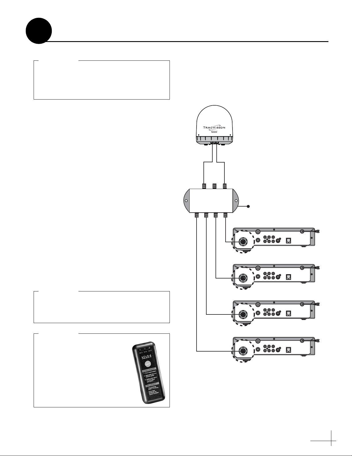
Figure 30: Multiswitch Wiring - Antenna with Circular Dual LNB
Antenna with Circular Dual LNB
(North American systems only)
To connect three or more receivers, follow these
steps to install an active (powered) multiswitch
between the antenna and the receivers.
NOTE: You can purchase an active multiswitch,
Channel Master model 6314IFD, from KVH (order
part #19-0123).
1. Connect the RF1 cable from the antenna to
the “RHCP +13V” jack on the multiswitch
(see Figure 30).
2. Connect the RF2 cable from the antenna to
the “LHCP +18V” jack on the multiswitch.
3. Connect the receivers to the individual
outputs of the multiswitch.
4. Terminate any unused multiswitch outputs
with 75 ohm DC blocks (Channel Master
#7184, Radio Shack #15-1259, or equivalent).
RHCP
+13V
RF2RF1
Multiswitch
Antenna
LHCP
+18V
DC Power
Receiver #1
SATELLITE IN
Receiver #2
SATELLITE IN
TV ANT/CABLE IN
OUT TO TV
TV ANT/CABLE IN
OUT TO TV
RL
AUDIO VIDEO S-VIDEO PHONE JACK
RL
AUDIO VIDEO S-VIDEO PHONE JACK
IMPORTANT!
Be sure the multiswitch is properly grounded.
With the multiswitch grounded, you do not
need to ground the individual receivers.
IMPORTANT!
(DIRECTV only) Multiswitches
block a receiver’s 22 KHz tone
that the antenna needs to switch
satellites automatically.
Therefore, the customer will need
to manually switch satellites
using the optional TV/SAT
Switch (KVH part #01-0245).
Receiver #3
TV ANT/CABLE IN
OUT TO TV
SATELLITE IN
Receiver #4
TV ANT/CABLE IN
OUT TO TV
SATELLITE IN
RL
AUDIO VIDEO S-VIDEO PHONE JACK
RL
AUDIO VIDEO S-VIDEO PHONE JACK
21
Page 21
SATELLITE IN
SATELLITE IN
SATELLITE IN
SATELLITE IN
A
Continued...
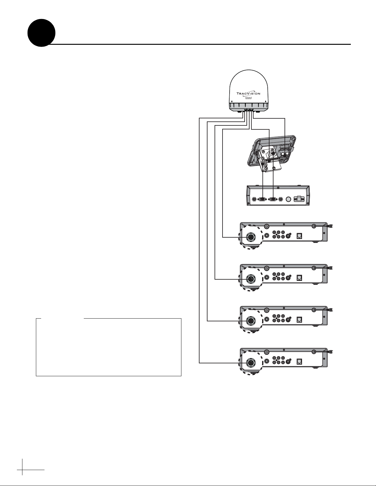
Antenna with Linear Quad LNB
(European systems only)
Follow these steps to connect three or four
receivers directly to the antenna.
NOTE: If you need to connect more than four
receivers to the TracVision system, install an active
multiswitch that generates a 22 KHz tone (such as
Spaun model 5602NF - KVH part #19-0413).
Connect the multiswitch in accordance with the
manufacturer’s instructions.
1. Decide which receiver will be the primary
receiver. The primary receiver will control
satellite selection.
NOTE: The additional receivers will be able to
select any channel carried on the satellite that is
currently selected on the primary receiver.
2. Connect the RF1 cable from the antenna to
the “Satellite In” jack on the primary receiver
(see Figure 31).
3. Connect the RF2 cable from the antenna to
the “Satellite In” jack on the second receiver.
4. Connect the RF3 cable from the antenna to
the “Satellite In” jack on the third receiver.
Figure 31: Receiver Wiring - Antenna with Linear Quad LNB
Antenna
Power
Data
Switchplate
–
+
MCP
HDTV
CONTROL
Receiver #1 (Primary)
RF1
SATELLITE IN
Receiver #2
RF2
SATELLITE IN
ANTENNA UNIT RF PORT TONE
TV ANT/CABLE IN
OUT TO TV
TV ANT/CABLE IN
OUT TO TV
FUSE POWER IN
DETECT
RL
AUDIO VIDEO S-VIDEO PHONE JACK
+ / –
This receiver controls
satellite selection
RL
AUDIO VIDEO S-VIDEO PHONE JACK
5. Connect the RF4 cable from the antenna to
the “Satellite In” jack on the fourth receiver.
IMPORTANT!
Be sure all receivers are grounded. If the
receiver has a 2-prong power plug, run a
ground wire from the receiver’s chassis to a
suitable ground point. If a potential exists
between AC and DC grounds, connect the
wire to the switchplate’s DC return instead.
22
RF3
RF4
Receiver #3
TV ANT/CABLE IN
OUT TO TV
SATELLITE IN
Receiver #4
TV ANT/CABLE IN
OUT TO TV
SATELLITE IN
RL
AUDIO VIDEO S-VIDEO PHONE JACK
RL
AUDIO VIDEO S-VIDEO PHONE JACK
Page 22
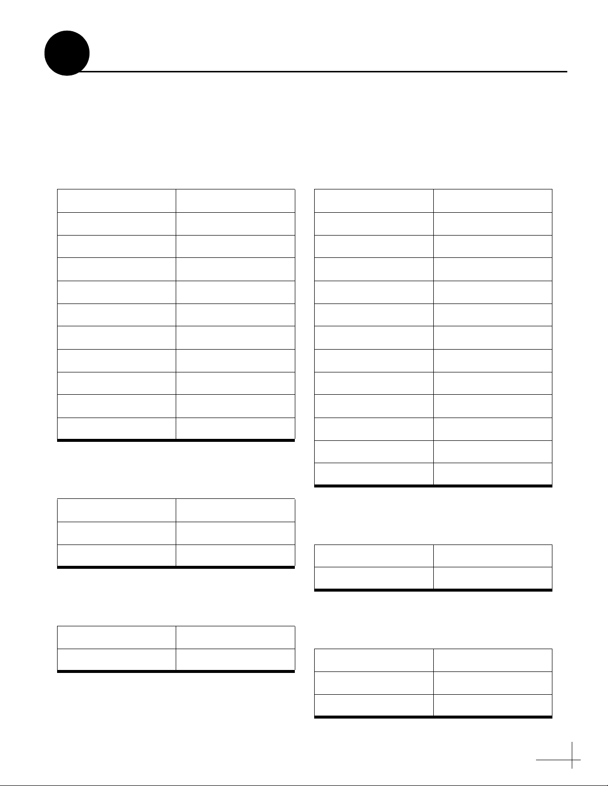
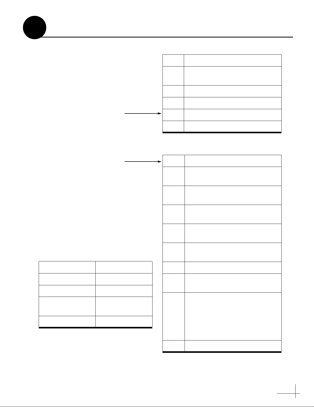
B
Satellite Library
The TracVision antenna can track a variety of
DVB-compatible and DSS (DIRECTV) satellites.
Most popular satellites are programmed in the
antenna’s library (see the tables below).
North America
Standard Circular Dual LNB Required
Satellite, Longitude Name in Library
DIRECTV, 72°W DSS_72
DIRECTV, 101°W DSS_101
DIRECTV, 110°W DSS_110
DIRECTV, 119°W DSS_119
EchoStar, 61°W ECHO_61
EchoStar, 110°W ECHO_110
EchoStar, 119°W ECHO_119
Appendix
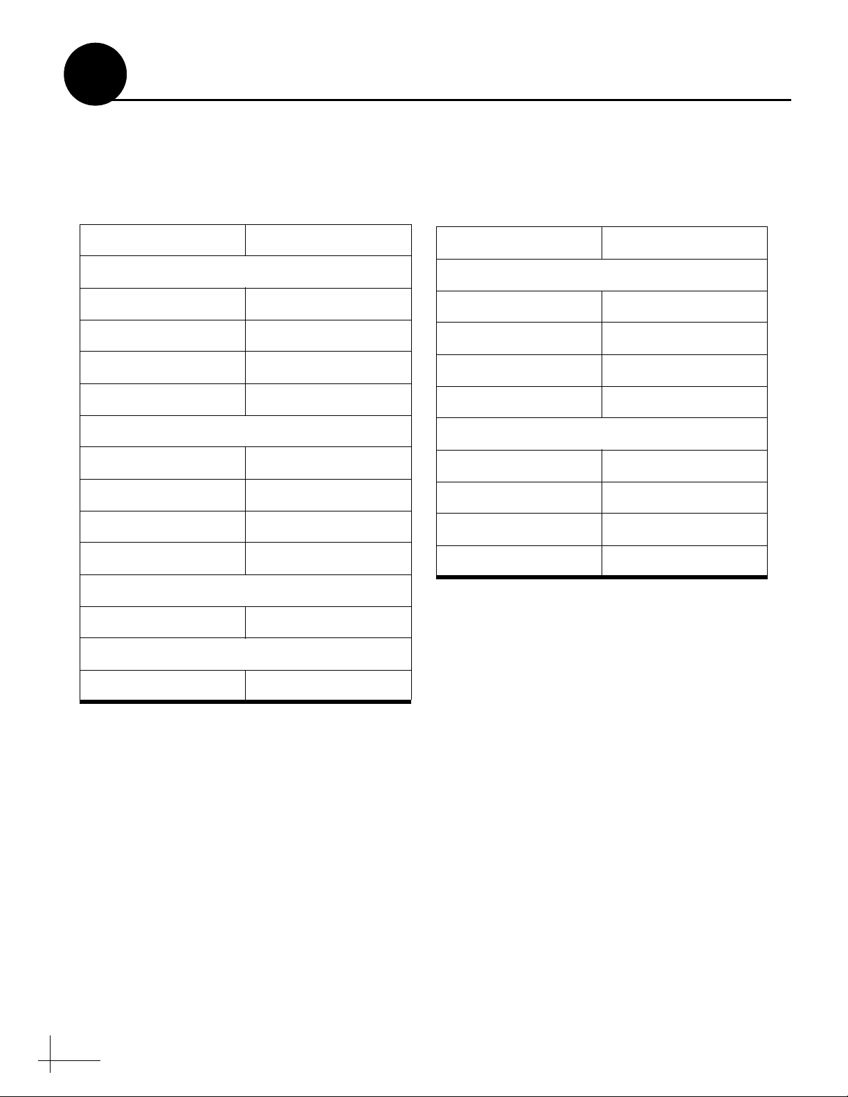
Europe
Linear Dual or Linear Quad LNB Required
Satellite Name in Library
Astra 1, 19.2°E ASTRA1
Astra 2N, 28.2°E ASTRA2N
Astra 2S, 28.2°E ASTRA2S
Hispasat, 30.0°W HISPASAT
Hotbird, 13.0°E HOTBIRD
Hotbird WB, 13.0°E HOTBIRDWB
Sirius, 5.0°E SIRIUS
EchoStar, 148°W ECHO_148
ExpressVu, 82°W EXPRESSVU
ExpressVu, 91°W EXPRESSTV
Asia
Standard Circular Dual LNB Required
Satellite Name in Library
Asiasat 4, 122.2°E ASIASAT
Sinosat 1*, 110.5°E SINOSAT
Latin America
Galaxy Circular Dual LNB Required
Satellite Name in Library
Galaxy 3C, 95°W GALAXY3CN
Thor, 0.8°W THOR
Arabsat, 26°E ARABSAT
Nilesat, 7°W NILESAT
Turksat 1C, 42°E TURKSAT1C
Eutelsat W3A, 7°E EUTEL_W3A
Mexico
Linear Dual LNB Required
Satellite Name in Library
PAS 9, 58°W PAS_9
Australia & New Zealand
Linear Dual LNB Required
Satellite Name in Library
Optus B1*, 160°E OPTUS_B1
Optus C1, 156°E OPTUS_C1
* Special LNB required. Call KVH at 1-401-847-3327.
23
Page 23
C
User-Defined Satellites
The satellite library in the TracVision antenna
includes two slots for user-defined satellites
(USER 1 and USER 2). You can program one or
both of these library slots for any satellite you
wish that is not already set up in the library.
To configure a user-defined satellite, you will
need to program into the antenna the following
information about the satellite (see Figure 32):
• Satellite name
• Satellite longitudinal position
• Transponder information for all
combinations of polarization and band:
•vertical high
•vertical low
• horizontal high
• horizontal low
OR
•right
•left
Appendix
Figure 32: Identifying a Linear Satellite
Name
Longitude
Decoder type
Vertical High: Vertical Low:
Frequency Frequency
Symbol rate Symbol rate
FEC code FEC code
Network ID Network ID
Horizontal High: Horizontal Low:
Frequency Frequency
Symbol rate Symbol rate
FEC code FEC code
Network ID Network ID
•Frequency
•Symbol rate
•FEC code rate
• Network ID
•Decoder type
NOTE: You can find this satellite information on the
web at www.lyngsat.com or www.satcodx.com
(neither website is affiliated with KVH).
24
Page 24
C
Continued...
Enter the following commands via Windows
HyperTerminal or KVH Flash Update Wizard.
1. Type HALT then press Enter.
2. Type DEBUGON then press Enter.
3. Type the following SATCONFIG command
then press Enter. Italics indicate a variable
field (see Figure 33 for definitions).
SATCONFIG,USERA,B,C,D,E
4. Type @DEBUGON then press Enter.
5. Type the following @SATCONFIG
command then press Enter. Italics indicate a
variable field (see Figure 34 for definitions).
@SATCONFIG,F,G,H,I,J,K,L,M,N
6. Repeat Step C5 for each polarization/band:
• Vertical High
•Vertical Low
OR
•Right •Left
• Horizontal High
• Horizontal Low
Figure 33: SATCONFIG Command Fields
Field Description
A User-defined satellite in library
(1=User 1; 2=User 2)
B Longitude (0-180)
C E (East) or W (West)
DDecoding type (2=DSS, 3=DVB)
E Polarization (C=circular, L=linear)
Figure 34: @SATCONFIG Command Fields
Field Description
F User-defined satellite in library
(A=User 1; B=User 2)
G Satellite table # (98=User 1;
99=User 2)
H Frequency, MHz (00000 or
10700-12750)
If your selected satellite does not have data
for one or more of these transponder
categories, you can enter the following
defaults instead:
Transponder Data Default Value
Frequency 00000
Symbol rate 27500
FEC code rate Same value as other
transponders
Network ID 0x0000
7. Type ZAP then press Enter. The antenna
restarts. Wait two minutes for system startup.
8. Follow the instructions in Step 13 on page 16
to select your new USER 1 or USER 2 satellite.
I Symbol rate, kilosymbols per
second (01000-45000)
J FEC code rate (12, 23, 34, 56, 67,
or 78)
K Network ID, hexadecimal (0x####)
L Polarization (V=vertical;
H=horizontal; R=right; L=left)
MLNB down conversion frequency
(L=low [9750 MHz];
H=high [10600 MHz];
G=Galaxy [10500 MHz];
S=Sinosat [11300 MHz];
U=USA [11250 MHz])
N Decoding type (2=DSS; 3=DVB)
25
Page 25
C
Continued...
Example - Linear Satellite
The following is an example of programming a
linear user-defined satellite (USER 1).
Satellite Name: YOURSAT 123 at 7°W
Transponder Data Value
Horizontal High
Frequency 11.966 GHz
Symbol rate 27500
FEC code rate 3/4
Network ID 2048 (dec) = 0x0800
Vertical High
Frequency 11.823 GHz
Symbol rate 27500
FEC code rate 3/4
Example - Circular Satellite
The following is an example of programming a
circular user-defined satellite (USER 1).
Satellite Name: YOURSAT 456 at 122°W
Transponder Data Value
Right
Frequency 12.225 GHz
Symbol rate 20000
FEC code rate 5/6
Network ID 4100 (dec) = 0x1004
Left
Frequency 12.456 GHz
Symbol rate 20000
FEC code rate 5/6
Network ID 2048 (dec) = 0x0800
Vertical Low
No data listed
Horizontal Low
No data listed
Commands you would enter into the antenna via
HyperTerminal or KVH Flash Update Wizard:
HALT
DEBUGON
SATCONFIG,USER1,7,W,3,L
@DEBUGON
@SATCONFIG,A,98,11966,27500,34,0x0800,H,H,3
@SATCONFIG,A,98,11823,27500,34,0x0800,V,H,3
@SATCONFIG,A,98,00000,27500,34,0x0000,V,L,3
@SATCONFIG,A,98,00000,27500,34,0x0000,H,L,3
ZAP
Network ID 4100 (dec) = 0x1004
Commands you would enter into the antenna via
HyperTerminal or KVH Flash Update Wizard:
HALT
DEBUGON
SATCONFIG,USER1,122,W,3,C
@DEBUGON
@SATCONFIG,A,98,12225,20000,56,0x1004,R,U,3
@SATCONFIG,A,98,12456,20000,56,0x1004,L,U,3
ZAP
26
Page 26

D
Wiring Diagrams
This appendix provides system wiring diagrams
for the following receiver configurations:
• One or two receivers
• Three or more receivers (circular)
• Three or more receivers (linear quad)
IMPORTANT!
The wiring diagrams on the following pages
are intended as a quick reference only. Be
sure to follow the complete wiring
instructions provided earlier in this manual.
Appendix
27
Page 27

D
SATELLITE IN
SATELLITE IN
Continued...
Wiring One or Two Receivers
Antenna
Switchplate
RF1
+12 VDC
Primary Receiver
TV ANT/CABLE IN
SATELLITE IN
OUT TO TV
This receiver controls
satellite selection
+
–
+
–
RL
AUDIO VIDEO S-VIDEO PHONE JACK
Power
Data
28
RF2
Secondary Receiver - Optional
TV ANT/CABLE IN
RL
SATELLITE IN
OUT TO TV
AUDIO VIDEO S-VIDEO PHONE JACK
Page 28

D
SATELLITE IN
SATELLITE IN
SATELLITE IN
SATELLITE IN
Continued...
Wiring Three or Four Receivers (Circular)
Antenna
RHCP
+13V
RF1
Multiswitch
RF2
LHCP
+18V
+12 VDC
Switchplate
Receiver #1
SATELLITE IN
Receiver #2
SATELLITE IN
Power
Data
TV ANT/CABLE IN
OUT TO TV
TV ANT/CABLE IN
OUT TO TV
RL
AUDIO VIDEO S-VIDEO PHONE JACK
RL
AUDIO VIDEO S-VIDEO PHONE JACK
+12 VDC
+
–
+
–
Receiver #3
TV ANT/CABLE IN
SATELLITE IN
OUT TO TV
Receiver #4
TV ANT/CABLE IN
SATELLITE IN
OUT TO TV
RL
AUDIO VIDEO S-VIDEO PHONE JACK
RL
AUDIO VIDEO S-VIDEO PHONE JACK
29
Page 29

D
SATELLITE IN
SATELLITE IN
SATELLITE IN
SATELLITE IN
Continued...
Wiring Three or Four Receivers (Linear Quad)
Antenna
Power
Data
Switchplate
+
–
+
–
+12 VDC
RF1
RF2
RF3
RF4
Receiver #1 (Primary)
TV ANT/CABLE IN
RL
SATELLITE IN
OUT TO TV
AUDIO VIDEO S-VIDEO PHONE JACK
Receiver #2
TV ANT/CABLE IN
RL
SATELLITE IN
OUT TO TV
AUDIO VIDEO S-VIDEO PHONE JACK
Receiver #3
TV ANT/CABLE IN
RL
SATELLITE IN
OUT TO TV
AUDIO VIDEO S-VIDEO PHONE JACK
Receiver #4
TV ANT/CABLE IN
RL
SATELLITE IN
OUT TO TV
AUDIO VIDEO S-VIDEO PHONE JACK
30
Page 30

" (2.25 mm)
32
/
3
Switchplate Mounting Template
2.05"
(52 mm)
3.82"
(97 mm)
3.19"
(81 mm)
Panel Cutout
.32" (8 mm)
2.36"
(60 mm)
.16" (4 mm)
31
Page 31

KVH Industries, Inc.
50 Enterprise Center Middletown, RI 02842-5279 U.S.A.
Phone: +1 401 847-3327 Fax: +1 401 849-0045
E-mail: info@kvh.com Internet: www.kvh.com
KVH Europe A/S
Kokkedal Industripark 2B 2980 Kokkedal Denmark
Phone: +45 45 160 180 Fax: +45 45 160 181
E-mail: info@kvh.dk Internet: www.kvh.com
© Copyright 2006 KVH Industries Inc. KVH and TracVision are registered trademarks of KVH Industries Inc.
 Loading...