

Page 1
Satellite Television
KVHTracVision
®
G4
technical
manual
•
Installation
•
Configuration
•
Maintenance
A Guide to TracVision G4
Page 2
TVG4_TM_cover_540147_Rev.J
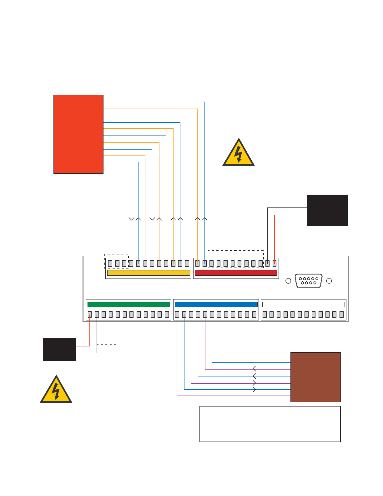
12 1110987612543 13 14 232221201918 24171615 25 26 353433323130 36292827
48 47 383940414243 3744454660 59 505152535455 49565758
Green/White
White/Green
Blue/White
White/Blue
Brown/White
White/Brown
Gray/White
White/Orange
Orange/White
White/Gray
Data Cable
Black
Red
TracVision
Power
Ground
+12 VDC
Ship’s
Power
(11-16 VDC)
Not
Used
Not Used
Green/White
White/Green
White/Blue
Blue/White
White/Orange
Orange/White
GyroTrac Sensor
Module Cable
Wiring Color Code Definitions
First Color: Wire
Second Color: Tracer
Example: Red/Orange = Red Wire with Orange Tracer
TracVision G4 will suffer serious
damage if connected to power in
excess of 16 VDC. Complete details
regarding connecting TracVision G4
to ship's power have been provided in
"Connecting
the ADCU to Vessel Power" on page 37.
Gyro Power
Ground
Gyro RXD+
Gyro RXD-
Gyro TXD-
Gyro TXD+
Not Used
IRD Ground Wire
(to IRD)
TracVision G4 can either receive power
through the ADCU (as illustrated in
the diagram) or directly from ship’s
power if that is more convenient.
Refer to
"Alternate Method of Providing Power to
the Antenna" on page 32
for details.
TracVision®G4 Wiring Quick Reference Guide
Page 3
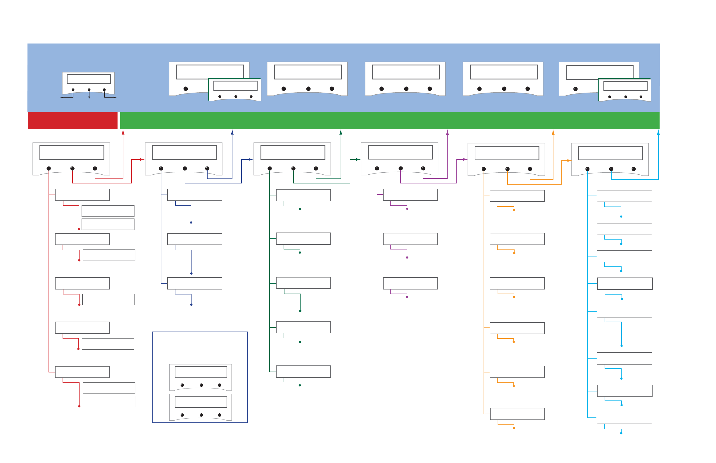
GyroTrac Mode Menus
Setup display type?
Enter Next Return
Setup data outputs?
Yes Next Return
Setup configuration?
Yes Next Return
Get Antenna status?
Enter Next Return
control antenna?
Enter Next Return
Select Mag/True
Select Serial Port 1, 2, or 3
Set NMEA Outputs
Select Mag/True
Control Compass?
Enter Next Return
Autocalibration On or Off
Calibration Accuracy, Magnetic
Environment, and Calibration #
Compass Calibration Reset
Set AutoCal On/Off?
Yes Next Return
Read Cal score?
Yes Next Return
Clear Compass Cal?
Yes Next Return
The Control Compass Menus are only
available if the selected heading
reference source is INTERNAL.
Magnetic Heading
###.#°
Mag/HDG True/HDG
###.#° ###.#°
Pitch Roll Yaw
#.#° #.#° #.#°
Mag/Hdg Rate/Sec
#.#° #.#°
Tracking <Sat Name>
###.#° ##.#° ####
ANTENNA Initializing
No Antenna Information
Lat: ##
Long: ##
compass?
Yes Next Return
Pitch, Roll & Yaw?
Yes Next Return
Rate of Turn?
Yes Next Return
Latitude Longitude?
Yes Next Return
Antenna display?
Yes Next Return
Set Reference Voltage
Set Swing Voltage
Set Speed
Select Output Type
Set Data Rate
Set sine-cos levels?
Yes Next Return
Set serial outputs?
Yes Next Return
Set Furuno outputs?
Yes Next Return
Select Internal or External
Heading Reference Source
TV Antenna Communication
On or Off
Set Heading int/ext?
Yes Next Return
Set Gyro Offsets?
Yes Next Return
Default Display box?
Yes Next Return
Set TV com on/off?
Yes Next Return
Display Default
Set Offset Roll
Set Offset Yaw
Set Offset Pitch
Errors Detected
Antenna Type and Version
Antenna Serial Number
Threshold and
Signal Levels
LNB Skew Angle
Get System Errors?
Yes Next Return
Get Thres/sig level?
Yes Next Return
Get version?
Yes Next Return
Get serial number?
Yes Next Return
Get skew angle?
Yes Next Return
Bit Error Rate
Get bit error rate?
Yes Next Return
* ARE YOU SURE? *
Yes No
** WARNING **
Data will be HALTED
Alert Screens
Certain operations temporarily halt data
output. In this event, the ADCU will display a
set of alert screens. Select “Yes” to proceed,
“No” to return to the Main Data Display.
Dim or Brighten
ADCU Display
Set brightness?
Yes Next Return
Return to Selected Primary Display
GyroTrac™ Advanced Digital Control Unit (ADCU) Menu Quick Reference Guide
ADCU Primary Display Options
Pitch Roll Yaw
#.#° #.#° #.#°
Pitch, Roll, Yaw
Mag/Hdg Rate/Sec
#.#° #.#°
Rate of TurnCompass Displays*
* True North Display requires GPS data
Magnetic Heading
###.#°
Mag/HDG True/HDG
###.#° ###.#°
Antenna Displays
Tracking <Sat Name>
###.#° ##.#° ####
ANTENNA Initializing
No Antenna Information
SELECTED DISPLAY
Select Installed
Satellite A
Select Installed
Satellite B
Enter GyroTrac Mode Menus
Lat: ##
Long: ##
Latitude/Longitude
†
†
Lat/Long Display requires GPS data
See
"Alert Screens" on page 65
for more details.
See Section 3.3 for details See Section 3.4 for details See Section 3.5 for details See Section 3.6 for details See Section 3.7 for details See Section 3.8 for details
See Section 3.2 for details
Antenna Restarts
Set Latitude
Set Longitude
Select Active Satellite
Man control antenna?
Yes Next Return
Restart antenna?
Yes Next Return
Install satellite?
Yes Next Return
Set Lat/Long?
Yes Next Return
Adjust Azimuth
Adjust Elevation
Install Sat Pair
Set Latitude
Set Longitude
Restart Antenna
Sleep Mode On/Off
Set sleep on/off?
Yes Next Return
Instant On Mode On/Off
set instant on/off?
Yes Next Return
Update Frequency
Sat frequency scan?
Yes Next Return
Select Satellite?
Yes Next Return
Page 4
TracVision G4
Technical Manual
This manual provides detailed instructions on the proper
installation, configuration, troubleshooting, and maintenance of
the KVH TracVision G4 system. Complete instructions on how to
use the TracVision G4 system is provided in the TracVision G4
User’s Guide.
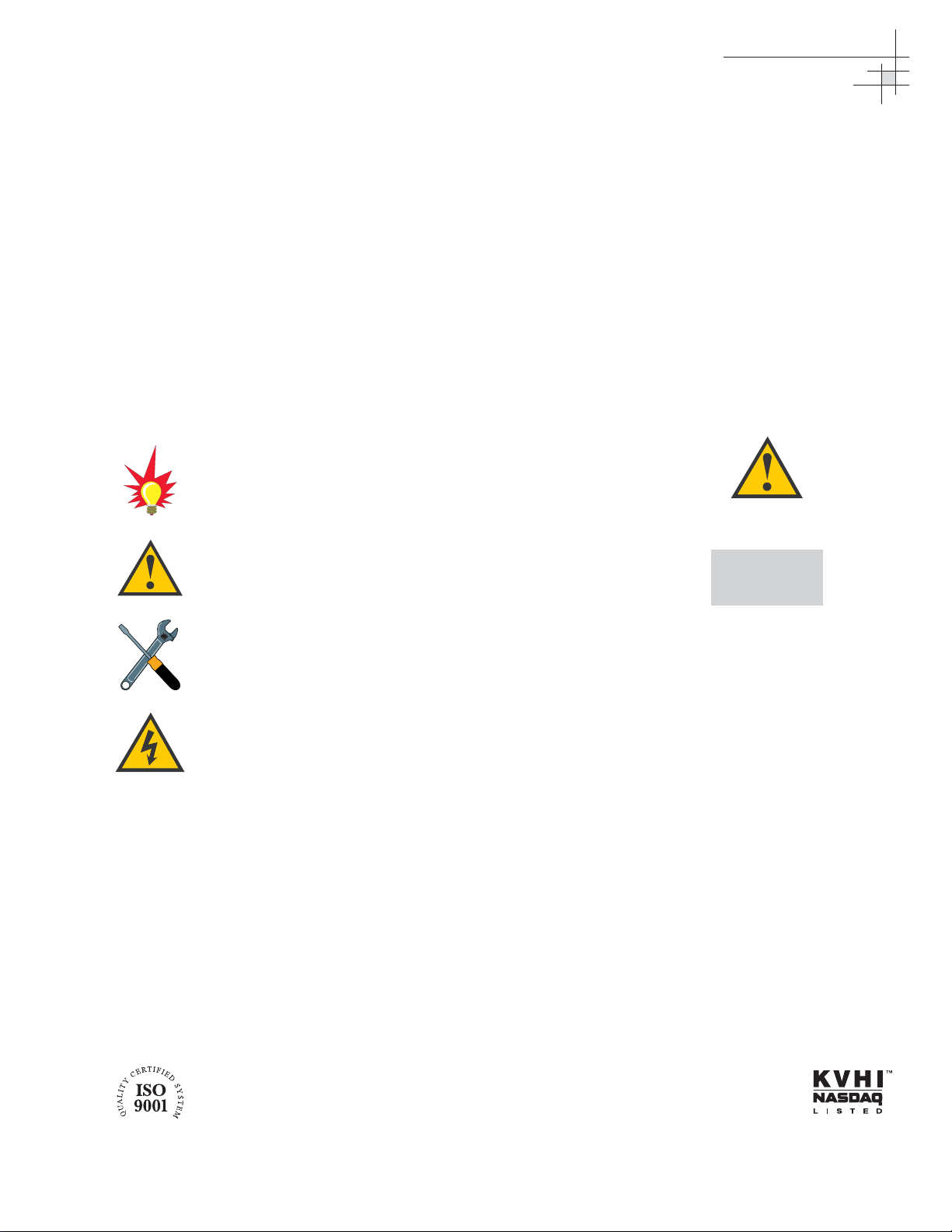
Throughout this manual, important information is marked for
your attention by these icons:
Direct questions, comments, or suggestions to:
KVH Industries, Inc. KVH Europe A/S
50 Enterprise Center Ved Klaedebo 12
Middletown, RI 02842-5279 USA 2970 Hoersholm Denmark
Tel: +1 401 847-3327 Tel: +45 45 16 01 80
Fax: +1 401 849-0045 Fax: +45 45 86 70 77
E-mail: info@kvh.com E-mail: info@kvh.dk
Internet: www.kvh.com Internet: www.kvh.com
If you have any comments regarding this manual, please e-mail
them to manuals@kvh.com. Your input is greatly appreciated!
KVH Part # 54-0147 Rev. J
© 2004, KVH Industries, Inc. All rights reserved.
TracVision G4 Serial Number
This serial number will be required
for all troubleshooting or service
calls made regarding this product.
Welcome to TracVision G4
Click here to go to our stateof-the-art Customer Support
web page...the fastest and
easiest way to get all of your
questions answered!
A helpful tip that either directs you to
a related area within the manual or
offers suggestions on getting the
best performance from your system.
An alert to important information
regarding procedures, product
specifications, or product use.
Information about installation,
maintenance, troubleshooting, or
other mechanical issues.
An electrical safety warning to help
identify electrical issues that can be a
hazard to either this KVH product or
a user.
Page 5

TracVision®and KVH®are registered trademarks
of KVH Industries, Inc.
GyroTrac
™
and TracNet™are trademarks of KVH Industries, Inc.
DVB
®
(Digital Video Broadcasting) is a registered trademark of the DVB Project.
DIRECTV
®
is an official trademark of DIRECTV, Inc.,
a unit of GM Hughes Electronics.
DISH Network
™
is an official trademark of
EchoStar Communications Corporation.
ExpressVu is a property of Bell ExpressVu, a wholly owned
subsidiary of Bell Satellite Services.
Cetrek
™
is a trademark of Cetrek USA.
Furuno
®
is a registered trademark of Furuno USA, Inc.
B&G®and Halcyon®are trademarks of Brooks and Gatehouse, Inc.
Page 6

54-0147
i
Table of Contents
Table of Contents
1 Introduction . . . . . . . . . . . . . . . . . . . . . . . . . . . . . . . . . .1
1.1 TracVision G4 System Overview . . . . . . . . . . . . . . . . . . . . .3
1.2 TracVision G4 Components . . . . . . . . . . . . . . . . . . . . . . . . .5
1.3 Materials Provided With the TracVision G4 . . . . . . . . . . . . .6
2 Installation . . . . . . . . . . . . . . . . . . . . . . . . . . . . . . . . . . .7
2.1 Planning the Installation . . . . . . . . . . . . . . . . . . . . . . . . . . . .9
2.2 Mounting the TracVision Antenna . . . . . . . . . . . . . . . . . . . .15
2.3 Mounting the GyroTrac Sensor . . . . . . . . . . . . . . . . . . . . .19
2.4 Mounting the ADCU . . . . . . . . . . . . . . . . . . . . . . . . . . . . . .24
2.5 Connecting the IRD(s) . . . . . . . . . . . . . . . . . . . . . . . . . . . .26
2.6 Wiring the ADCU . . . . . . . . . . . . . . . . . . . . . . . . . . . . . . . .29
2.7 Calibrating the Sensor . . . . . . . . . . . . . . . . . . . . . . . . . . . .40
2.8 Activating/Programming the IRD . . . . . . . . . . . . . . . . . . . .42
2.9 Installing Satellites Using the ADCU . . . . . . . . . . . . . . . . .44
2.10 Setting the Skew Angle
(European Systems Only) . . . . . . . . . . . . . . . . . . . . . . . . .54
2.11 Checking Out the System . . . . . . . . . . . . . . . . . . . . . . . . .55
2.12 Changing Geographic Location . . . . . . . . . . . . . . . . . . . . .57
3 Using the ADCU Interface . . . . . . . . . . . . . . . . . . . . . . . .59
3.1 Startup and Self-test . . . . . . . . . . . . . . . . . . . . . . . . . . . . .61
3.2 Data Display and Accessing the Main Menu . . . . . . . . . . .63
3.3 Setup Display Mode . . . . . . . . . . . . . . . . . . . . . . . . . . . . . .67
3.4 Set Data Outputs Mode . . . . . . . . . . . . . . . . . . . . . . . . . . .68
3.5 Set Configuration Mode . . . . . . . . . . . . . . . . . . . . . . . . . . .73
3.6 Control Compass Mode . . . . . . . . . . . . . . . . . . . . . . . . . . .77
3.7 Antenna Status Mode . . . . . . . . . . . . . . . . . . . . . . . . . . . . .79
3.8 Control Antenna Mode . . . . . . . . . . . . . . . . . . . . . . . . . . . .81
Page 7

4 Troubleshooting . . . . . . . . . . . . . . . . . . . . . . . . . . . . . . .91
4.1 Troubleshooting Matrix . . . . . . . . . . . . . . . . . . . . . . . . . . . .93
4.2 Causes and Remedies for Common
Operational Issues . . . . . . . . . . . . . . . . . . . . . . . . . . . . . . .94
4.3 GyroTrac-specific Issues . . . . . . . . . . . . . . . . . . . . . . . . . .97
Page 8

Introduction
54-0147
1
1 – Introduction
This section provides a basic overview of the TracVision G4 system. It
explains how the system works and describes the function of each
component.
Contents
1.1 TracVision G4 System Overview . . . . . . . . . . . . . . . . . . . . . . . . . . .3
1.2 TracVision G4 Components . . . . . . . . . . . . . . . . . . . . . . . . . . . . . . .5
1.3 Materials Provided With the TracVision G4 . . . . . . . . . . . . . . . . . . .6
Page 9
Introduction
54-0147
3
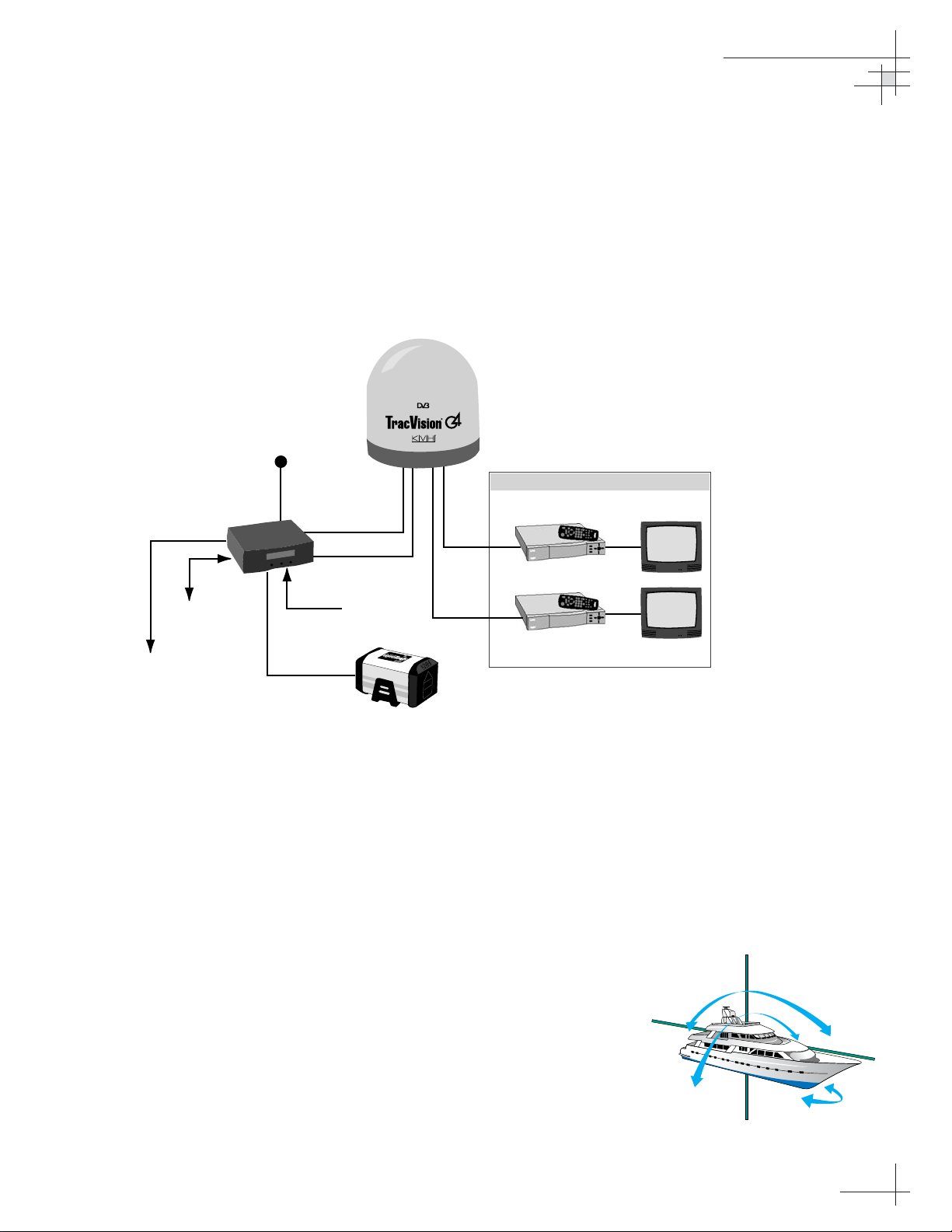
1.1 TracVision G4 System Overview
A complete satellite TV system, illustrated in Figure 1-1, includes
the TracVision G4 antenna unit connected to the GyroTrac digital
gyro-stabilized sensor, Advanced Digital Control Unit (ADCU),
an IRD (satellite TV receiver), and a television set. A desktop or
laptop computer is used to conduct diagnostics. System
specifications are provided in Appendix A on page 123.
System Compatibility
The TracVision G4 satellite antenna is fully compatible with
Digital Video Broadcasting (DVB
®
) satellites, as well as
DIRECTV
®
‘s Digital Satellite Service (DSS) satellites. The
system is also fully compatible with KVH’s TracNet
™
2.0 Mobile
High-speed Internet System (for more information about
TracNet 2.0, please visit our web site at www.kvh.com).
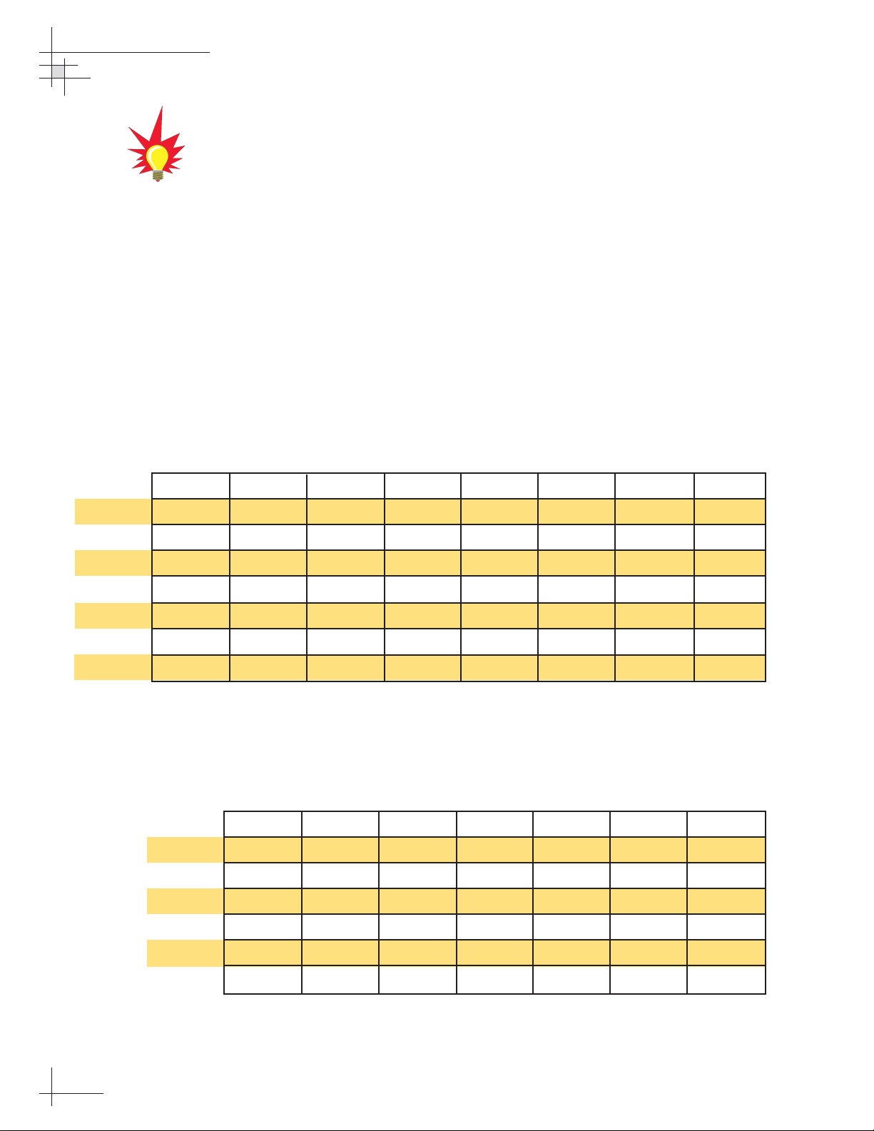
In-motion Tracking
The TracVision G4 uses a state-of-the-art actively stabilized
antenna system. Once the satellite is acquired, the antenna gyro
continuously measures the heading, pitch, and roll of your vessel
and sends commands to the antenna motors to keep the antenna
pointed at the satellite at all times.
Figure 1-1
TracVision G4 System Diagram
Figure 1-2
TracVision Identifies and
Compensates for Vessel Motion
Advanced Digital
Control Unit (ADCU)
PC Diagnostics
Interfaces to:
Autopilots
Radars
Plotters
Remote Displays
11-16 VDC
3.5 - 4.5 Amps
TracVision G4 Antenna
Powe r
Data
GPS or
Ship's Gyro
GyroTrac Sensor
Satellite Receiver 1
RF
RF
Satellite Receiver 2
Options Purchased Separately
TV 1
TV 2
TracVision
Page 10
54-0147
4
TracVision G4 Technical Manual
Satellite Library
Your TracVision G4 includes a pre-programmed satellite library
of North American and European satellite services. When
configuring the TracVision G4, you may choose a pair of satellites
from the library to be active in the system and with your IRD.
For the antenna to track and receive signals from two satellites,
they must be within 10º longitude of each other in orbit. As a
result, certain satellites can be paired only with certain other
satellites. Tables 1-1 and 1-2 list the possible satellite pairs that
may be selected in North America and Europe. If the satellite
service you wish to receive is not listed in the satellite library, you may
add two additional satellites of your choice to the library.
TracVision G4’s default satellite
pairs are:
N. America (US DIRECTV):
DSS_101 & DSS_119
Europe: Astra 1 & Hotbird
Table 1-2
Available Satellite Pairs - Europe
(European LNB required)
Table 1-1
Available Satellite Pairs
- North America
(North American LNB required)
DSS_101 DSS_119 Echo_61 Echo_110 Echo_119 Echo_148 Expressvu ExpressTV
DSS_101 ✓✓✓
DSS_119 ✓✓✓
Echo_61 ✓✓ ✓✓
Echo_110 ✓ ✓✓✓✓
Echo_119 ✓✓ ✓✓✓
Echo_148 ✓✓ ✓✓
Expressvu ✓✓✓✓✓✓ ✓
ExpressTV ✓✓✓✓✓✓✓
Astra 1 Astra 2N Astra 2S Hispasat Hotbird Sirius Thor
Astra 1 ✓✓ ✓✓
Astra 2N ✓✓
Astra 2S ✓✓
Hispasat
Hotbird ✓✓ ✓ ✓
Sirius ✓✓✓
Thor ✓
Page 11
1.2 TracVision G4 Components
Your TracVision G4 system includes the following components:
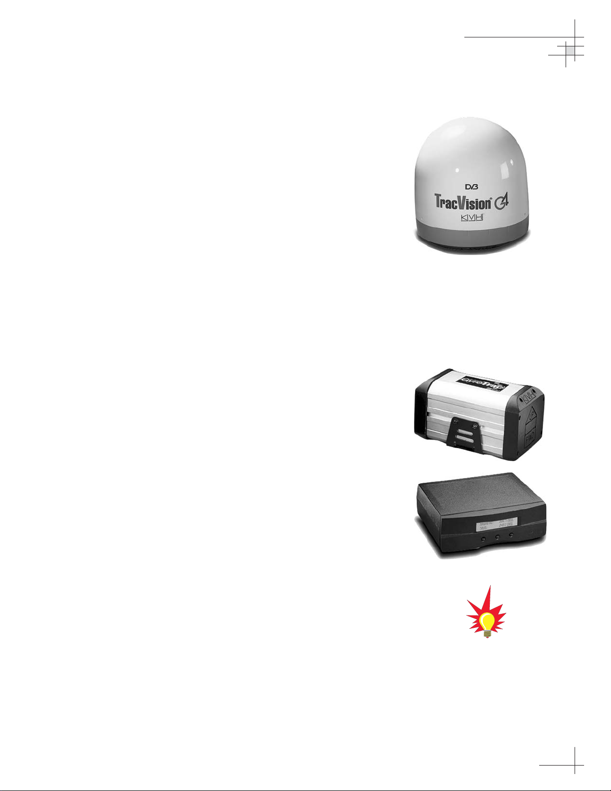
Antenna Unit
The antenna unit houses the antenna positioning mechanism, low
noise block (LNB), power supply, and control elements within a
molded ABS radome. Weathertight connectors on the bottom of
the baseplate join the power, signal, and control cabling from
belowdecks units.
GyroTrac
TracVision G4 includes KVH’s GyroTrac digital gyrocompass for
three-axis attitude/heading reference, ensuring superior open
water performance in any sea conditions. GyroTrac can also
operate as a fully functional, stand-alone heading sensor.
GyroTrac includes the following two components:
Sensor Module
The sensor module houses the system’s compass/yaw sensor,
inclinometer, rate gyros, and processing electronics and is
waterproof to a depth of one meter.
Advanced Digital Control Unit (ADCU)
The ADCU is the user interface, providing access to the system
and its functions through an LCD and three soft keys. The ADCU
also serves as the system’s junction box, allowing the system to
use ship’s power, interface with the sensor module, supply and
receive data to/from the TracVision G4 system, and supply and
receive data to/from other shipboard systems.
Integrated Receiver Decoder (IRD)
The IRD (purchased separately) receives satellite signals from the
antenna unit for signal processing and channel selection, and
sends the signals to the TV set for viewing. Please refer to the
user’s manual provided with your selected IRD for complete
operating instructions.
Introduction
54-0147
5
Before you can start watching
satellite TV using your TracVision
antenna, you will need to activate
your IRD. Refer to
Section 2.8,
“Activating/Programming the IRD”
on page 42
for details.
Page 12
1.3 Materials Provided With the
TracVision G4
Table 1-3 lists the components and materials in the TracVision G4
shipping carton.
Component KVH Part No.
Antenna Unit 02-0989-01
†
02-0989-02
††
Installation Kitpack 72-0099
Data Cable 32-0619-50
†
32-0619-100
††
PC Cable 32-0628-06
RF Cable* 32-0417-50
Power Cable 32-0510-50
Ground Cable 32-0583-50
TracVision G4 Technical Manual
54-0147
TracVision G4 User’s Guide
54-0147-01
GyroTrac, which includes: 01-0226-01
Sensor Module 02-1154
ADCU 02-0961
Flush Mount ADCU Panel 20-0667
Horizontal Sensor Bracket 20-0658
Vertical Sensor Bracket 20-0666
Sensor to ADCU Cable 32-0623-30
Kitpack 72-0095
†
North American system
††
European system
* Not included with European systems
54-0147
6
TracVision G4 Technical Manual
Table 1-3
TracVision G4 Packing List
For lists of items supplied in the
kitpacks, see Tables 2-3 and 2-4 on
page 10.
Page 13

Installation
54-0147
7
2 – Installation
This section explains how to install, configure, and test the
TracVision G4 system. Follow the simple procedures in this section
sequentially to ensure a safe and effective installation.
Contents
2.1 Planning the Installation . . . . . . . . . . . . . . . . . . . . . . . . . . . . . . . . .9
2.2 Mounting the TracVision Antenna . . . . . . . . . . . . . . . . . . . . . . . . .15
2.3 Mounting the GyroTrac Sensor . . . . . . . . . . . . . . . . . . . . . . . . . . .19
2.4 Mounting the ADCU . . . . . . . . . . . . . . . . . . . . . . . . . . . . . . . . . . . .24
2.5 Connecting the IRD(s) . . . . . . . . . . . . . . . . . . . . . . . . . . . . . . . . . .26
2.6 Wiring the ADCU . . . . . . . . . . . . . . . . . . . . . . . . . . . . . . . . . . . . . .29
2.7 Calibrating the Sensor . . . . . . . . . . . . . . . . . . . . . . . . . . . . . . . . . .40
2.8 Activating/Programming the IRD . . . . . . . . . . . . . . . . . . . . . . . . . .42
2.9 Installing Satellites Using the ADCU . . . . . . . . . . . . . . . . . . . . . . .44
2.10 Setting the Skew Angle
(European Systems Only) . . . . . . . . . . . . . . . . . . . . . . . . . . . . . . .54
2.11 Checking Out the System . . . . . . . . . . . . . . . . . . . . . . . . . . . . . . .55
2.12 Changing Geographic Location . . . . . . . . . . . . . . . . . . . . . . . . . . .57
Page 14
Installation
54-0147
9
2.1 Planning the Installation
Who Should Install the TracVision G4
KVH recommends that a KVH-authorized technician install the
TracVision G4 system. Installers should have experience
installing electronic equipment on a vessel.
Materials and Equipment Required for Installation
Before you begin installing the TracVision G4 system, you need to
verify that you have all of the following tools and materials:
• Electric drill
•
3
⁄8" (10 mm) drill bit and 3" (80 mm) hole saw
• Socket wrenches
•
7
⁄16" open end wrench
• Flat head and Phillips screwdrivers
• Crimp tool (Augat T1000 or equivalent)
• Light hammer; center punch; tape; scriber/pencil
• Terminal lug crimping tool; wire strippers
• A PC with terminal emulation software such as
Windows Hyperterminal or PROCOMM.
• RG-6 or RG-11 cable with F-type connectors for
extra RF signal cables as needed. Refer to Table 2-1
to determine the number of RF cables that you will
need.
Connecting to: # RF Cables
North American Systems
One IRD 1
Two or more IRDs 2*
European Systems
One IRD 1
Two IRDs 2
* Multiswitch needed for three or more IRDs. Follow multiswitch
manufacturer’s guidelines.
Plan the entire installation before
proceeding! Take into account
antenna unit placement, cable
running distances between units,
and accessibility to the equipment
after installation.
Table 2-1
Number of RF Cables to Connect
to the Antenna
RG-11 or RG-6 cable with F-type
connectors is required for all RF
wiring. Use of any other cable will
result in degraded performance.
Use RG-6 cable for distances up to
75 ft (23 m); use RG-11 cable for
distances greater than 75 ft (23 m).
The KVH warranty does not cover
degraded performance due to
improper wiring.
You may want to connect two RF
cables to the antenna in all cases.
That way, if an IRD is added in the
future, no additional RF cables will
need to be run.
Page 15

• Power cable to connect the ADCU to ship’s power
(Table 2-2 provides proper gauge and length
specifications).
Cable Length Cable Gauge
to 50 ft (15 m) 14 AWG (1.5 mm2)
+50 ft (+15 m) 12 AWG (2.5 mm2)
Kitpack Contents
The kitpacks packaged with your antenna unit and GyroTrac
contain various hardware and other materials that will be needed
to complete the TracVision system installation. Ensure that the
kitpacks contain all of the items listed in Tables 2-3 and 2-4.
Part Qty.
1
⁄4"-20 x 3" hex head screws 4
1
⁄4" flat washers 8
1
⁄4"-20 self-locking nuts 4
Plastic screw covers 6
Foam seal 1
Tie-wraps 2
Core clamp (ferrite) 1
Part Qty.
#8 fiber washers 10
#8 flat washers 10
#8-32 self-locking nuts 5
#10 flat washers 5
#10 lock washers 5
#10-32 Phillips head screws 5
#8 Phillips head screws 5
#8-32 Phillips head screws 5
#8 lock washers 5
#8 Phillips head (black) screws 5
Velcro self-adhesive backings 4
Velcro washers 4
4" tie-wraps 5
54-0147
10
TracVision G4 Technical Manual
Table 2-3
Antenna Unit Kitpack Contents
Table 2-4
GyroTrac Kitpack Contents
Table 2-2
Recommended ADCU-to-Ship’s
Power Cable Specifications
Page 16
Part Qty.
Tie-wrap screw mount 6
Terminal strip connectors 5
Sensor module to ADCU power wire ferrite 1
#4-24 thread-forming screws 4
Choosing Component Locations
The major considerations in locating the TracVision components
are described below.
Cable Lengths
When determining component locations, keep in mind
accessibility and cable lengths between units. Lengths of these
cables are as follows:
Cable (Function) Length
Data Cable (ADCU to Antenna Unit) 50 ft (15 m)
†
100 ft (30 m)
††
PC Cable (ADCU to PC) 6 ft (2 m)
RF Cable (Antenna to IRD)* 50 ft (15 m)
†
Power Cable (Power to Antenna Unit) 50 ft (15 m)
Sensor to ADCU Cable (GyroTrac) 30 ft (10 m)
IRD Ground to ADCU Ground Cable 50 ft (15 m)
†
North American system
††
European system
* Not included with European systems
Installation
54-0147
11
Table 2-5
Lengths of Provided
Belowdecks Cables
Table 2-4
GyroTrac Kitpack Contents
(Continued)
Page 17
Choosing the Best Location for the TracVision Antenna
There are several factors to consider when choosing the location
for the TracVision antenna.
• Since the TracVision antenna requires a clear view
of the southern sky to receive satellite signals, the
ideal antenna site has an unobstructed view of the
horizon/satellite all around. The less blockage, the
better the system performs.
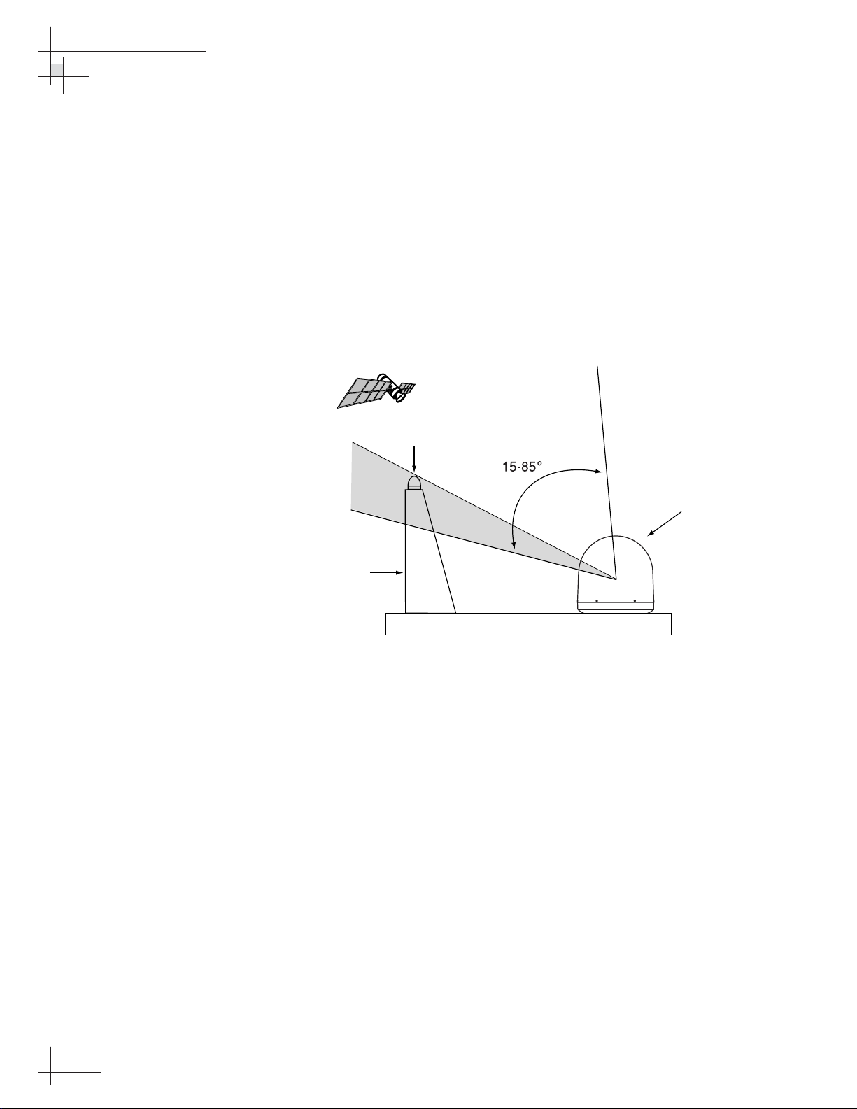
• Keep the antenna clear of any obstructions above
decks. The antenna requires a 15º to 85º look angle
to receive satellite signals.
• To minimize tracking errors, place the antenna
unit as close as possible to the intersection of the
vessel’s fore-and-aft centerline and midships. The
antenna unit need not be located exactly on the
vessel’s fore-and-aft axis, but its centerline MUST
be parallel to it.
• The mounting surface should be flat and strong
enough to carry the complete assembly (30 lbs/
13.6 kg). To prevent warpage to the antenna
baseplate, make sure that the mounting surface is
rigid so that it cannot flex when the vessel
vibrates. If necessary, add a strength member to
the mounting site to stiffen it.
• Be sure to account for the height and base
dimensions (see Figure 2-2 on the following page).
54-0147
12
TracVision G4 Technical Manual
Figure 2-1
Antenna Blockage
Blocked!
TracVision Antenna
Mast
Vessel Platform
Page 18
Radar Concerns
The TracVision antenna must be kept out of line with nearby
radars, as their energy levels may overload the antenna’s frontend circuits. In an ideal installation, the antenna is mounted four
feet (1.2 m) above and four feet (1.2 m) away from the radar
(measured from the center of the antenna dome to the center of
the radar).
The best placement for the TracVision antenna is above the radar.
However, if there will be a significant horizontal separation
between the radar and TV dome (i.e., at least 8 to 10 feet (2.5 to
3 m)), the TracVision antenna can be placed below the radar as
there will be little chance of signal blockage.
Installation
54-0147
13
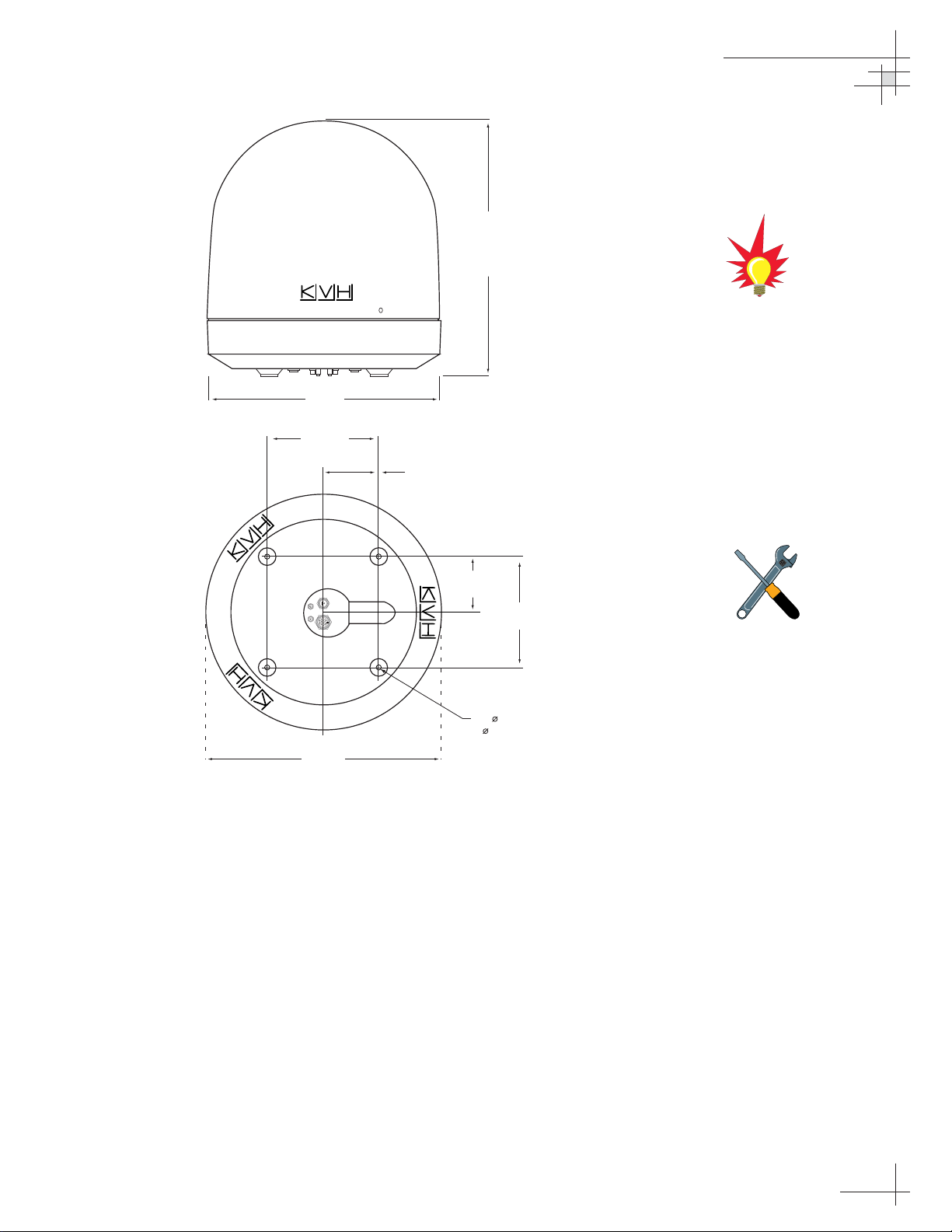
Figure 2-2
Antenna Unit Dimensions
The radome exterior is treated
with a special finish selected for
compatibility with the dome material
and transparency to the satellite
signals. Application of additional
paints or finishes WILL degrade
performance, potentially beyond
acceptable limits.
A full-size template of the baseplate
mounting holes has been provided
in
Appendix B on page 127
.
19.3"
49 cm
9"
(22.9 cm)
4.5"
(11.4 cm)
21" Max
54 cm
4.5"
(11.4 cm)
9"
(23 cm)
4 x 5/16"
( 8 mm)
19.3"
(49 cm)
Page 19
Choosing the Best Location for the GyroTrac Sensor
• Ideally, the sensor module should be mounted as
low as possible in the center of the vessel – but
NOT in the bilge.
• The mounting surface should be free of excessive
vibration and flexing.
• Maintain at least four feet (1.3 m) separation
between the sensor module and any magnetized
materials, large ferrous masses, cranes, engines,
derricks, other antennas, cables carrying high
amperage direct current, or battery banks.
• Take extra care when mounting the sensor module
on a steel vessel. Enclose the sensor module in a
fiberglass container and use an aluminum, brass,
plastic, or wood (NOT steel or iron) platform to
position the sensor at least four feet (1.2 m) above
and six feet (1.8 m) away from the steel surface.
• Be alert for devices that change their magnetic
characteristics when in use, such as CRTs
(computer and TV screens), radar magnetrons,
electric winches, loudspeakers, windshield wipers,
and other devices with DC motors. GyroTrac
cannot compensate for changing magnetic fields
created by these devices.
• If you need to fabricate custom mounting brackets
for the sensor module, they should be made from
non-ferrous materials such as wood, brass,
aluminum, fiberglass, or plastic. Be sure to use
stainless steel bolts or nails.
Choosing the Best Location for the ADCU
• The ADCU should be mounted in a dry location,
allowing enough room at the back for connecting
system cables.
• The ADCU should be placed so that the LCD
display is visible and the buttons are accessible.
• The ADCU is not susceptible to magnetic
interference and does not need to be mounted on a
level surface.
54-0147
14
TracVision G4 Technical Manual
If uncertain of the best location
for the sensor module, make a
temporary installation and conduct
a calibration (as described in
Section 2.7, “Calibrating the
Sensor” on page 40
). Any
necessary adjustments to the
sensor location can be made based
on the calibration scores.
Page 20
2.2 Mounting the TracVision
Antenna
1. Make sure that you have chosen a suitable
mounting location based upon the guidelines in
“Choosing the Best Location for the TracVision
Antenna” on page 12.
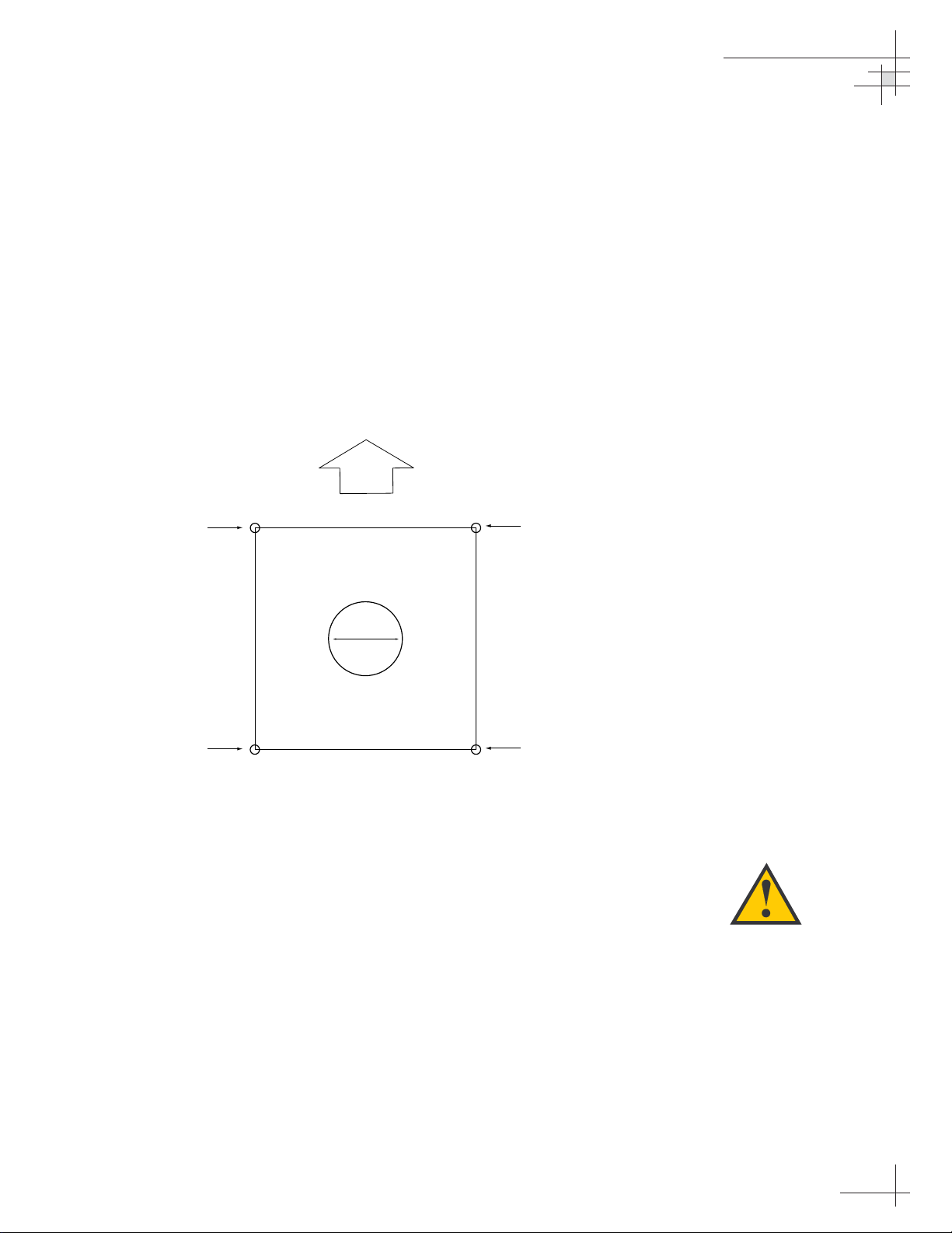
2. Using the template provided in Appendix B on
page 127 or the dimensions shown in Figure 2-3,
lay out the four mounting bolt holes and cable
access hole at the mounting site. Make certain that
the “FWD” arrow is parallel with the vessel’s
centerline and pointed toward the bow.
3. Drill the four
3
⁄8" (10 mm) bolt holes and cut out the
3" (80 mm) diameter cable access hole (following
the layout in Step 2). Smooth the edges of the cable
access hole to protect the cables.
4. Bring the data cable, power cable, and RF cable(s)
from belowdecks up through the cable access hole
in the mounting surface (see Table 2-1 on page 9 to
determine the number of RF cables required).
5. Remove the antenna unit from its shipping carton.
Installation
54-0147
15
Always lift the antenna unit by the
gray baseplate and never by the
radome or any portion of the
antenna assembly. Also be careful
not to strike the exposed
connectors extending from the
bottom of the baseplate or allow
them to carry the weight of the
antenna unit.
Figure 2-3
Antenna Mounting Holes Layout
FWD
Drill 3/8" (10 mm)
Bolt Hole
9" (229 mm)
Drill 3/8" (10 mm)
Bolt Hole
9" (229 mm)
r
o
f
t
u
o
t
u
C
3" (80 mm)
9" (229 mm)
a
C
b
l
e
A
c
c
e
s
s
9" (229 mm)
Drill 3/8" (10 mm)
Bolt Hole
Drill 3/8" (10 mm)
Bolt Hole
Page 21
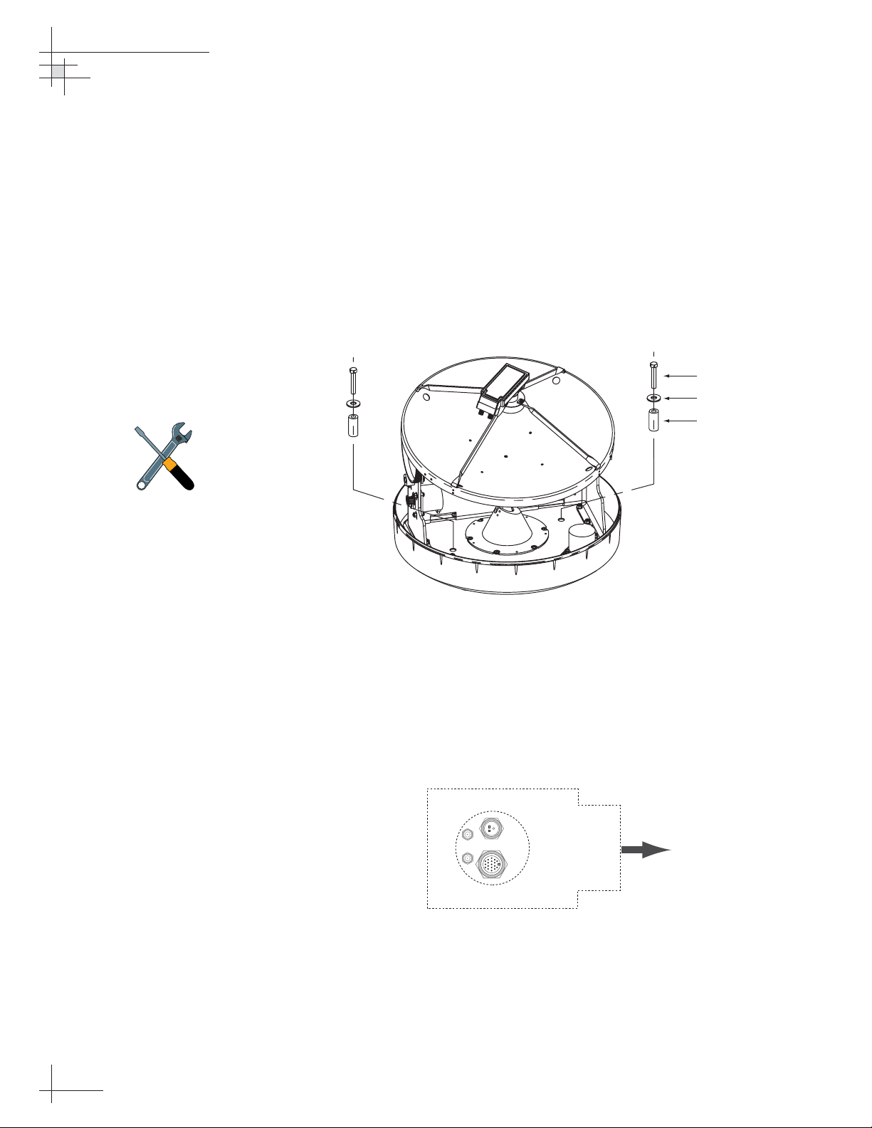
6. Remove and save the three screws securing the
radome to the baseplate. Carefully lift the radome
straight up until clear of the antenna assembly and
set it aside in a safe place. If you bring the radome
topside, be sure to secure it with a lanyard so that
it does not fall overboard.
7. Remove the foam shipping restraint from the
antenna unit.
8. Using a 10 mm wrench, remove the two azimuth
shipping restraint bolts, washers, and spacers from
the antenna unit, as shown in Figure 2-4.
9. Place the foam seal in position on the mounting
surface with the hole centered over the cable
access cutout. Do not remove the paper backing at
this time. Align the seal with the vessel’s centerline
and the narrow end pointing toward the bow (see
Figure 2-5). Scribe a line all around the seal.
54-0147
16
TracVision G4 Technical Manual
Figure 2-5
Baseplate/Foam Seal Orientation
(Bottom View)
Figure 2-4
Azimuth Shipping
Restraint Removal
The shipping restraints must be
removed before power is applied.
Save the restraints for reuse and be
sure to install them whenever the
antenna unit is moved from place to
place. See
Section 5.10, “Preparing
for Shipment” on page 118
for
instructions on preparing for
shipment.
Bolt
Washer
Spacer
Foam Seal
Powe r
RF1
RF2
Data
Bow
Page 22
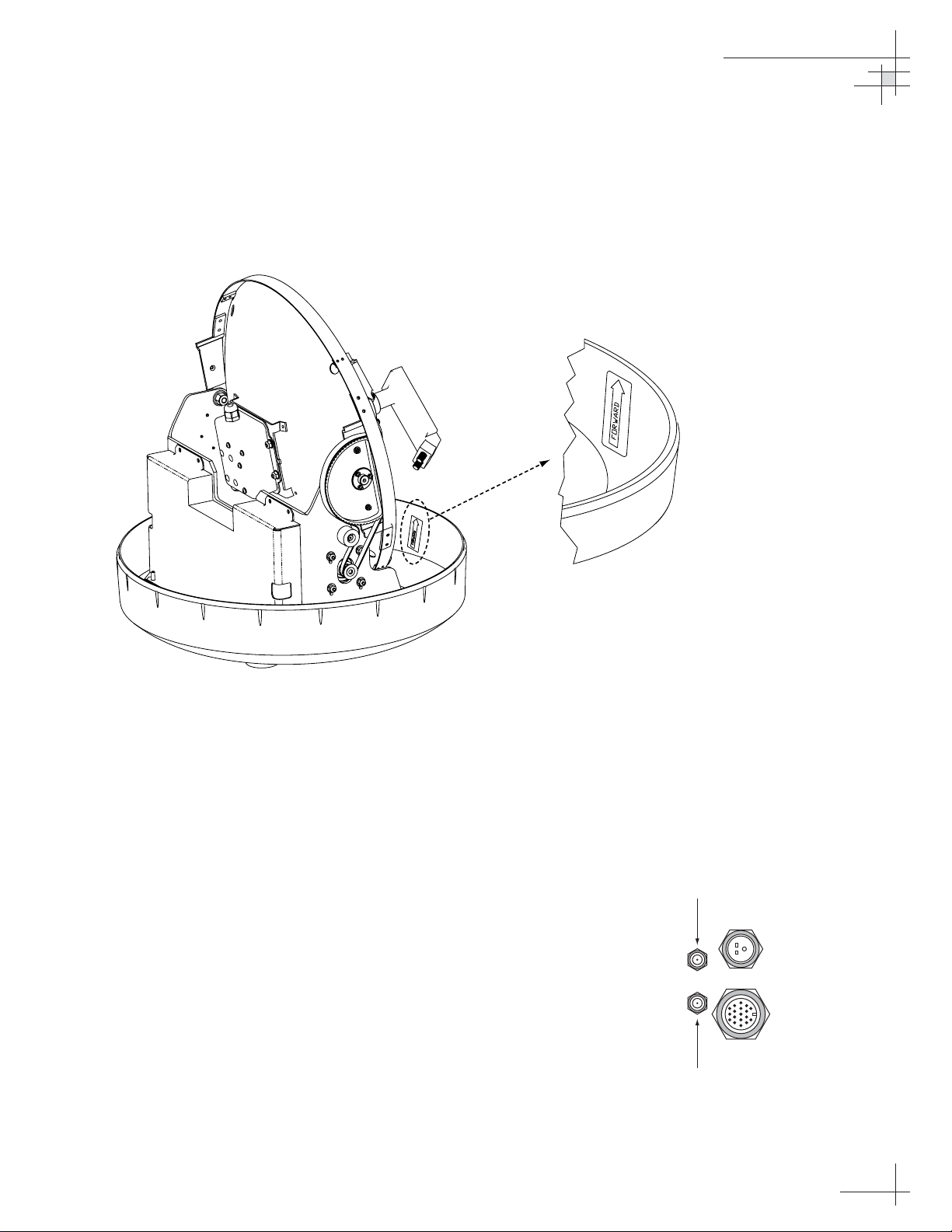
10. Position the baseplate assembly in place over the
mounting holes and cable access, with the
baseplate’s “Forward” arrow (shown in Figure 2-6)
pointing toward the bow. Ensure that all holes line
up and that the connectors are centered over the
cable access. Make any necessary adjustments
before seating the foam seal in place permanently.
11. Clean the mounting surface where the foam seal
will be placed. Remove the paper backing from the
foam seal to expose the contact cement, then lay
the foam seal in place, adhesive side down, and
press down firmly to bring the adhesive into full
contact along the bottom. Ensure the narrow end
points toward the bow.
12. Connect the data, power, and RF cables from
belowdecks to the baseplate as shown in
Figure 2-7. Turn the power and data cable
connectors down until locked in place; don’t use
excessive force. Connect the RF cable(s) using a
7
⁄16"
wrench, applying 30 pounds of torque. If you
connect more than one RF cable, label both ends of
each RF cable to match its antenna baseplate
connector (RF1 or RF2). Do NOT use teflon gel on
the cable fittings as it reduces signal strength at
higher frequencies.
Installation
54-0147
17
Figure 2-6
Baseplate “Forward” Arrow
Figure 2-7
Baseplate Connector Assignments
(Bottom View)
Single IRD
Installation
RF1
RF2
Second IRD
Installation
Power
Data
Page 23
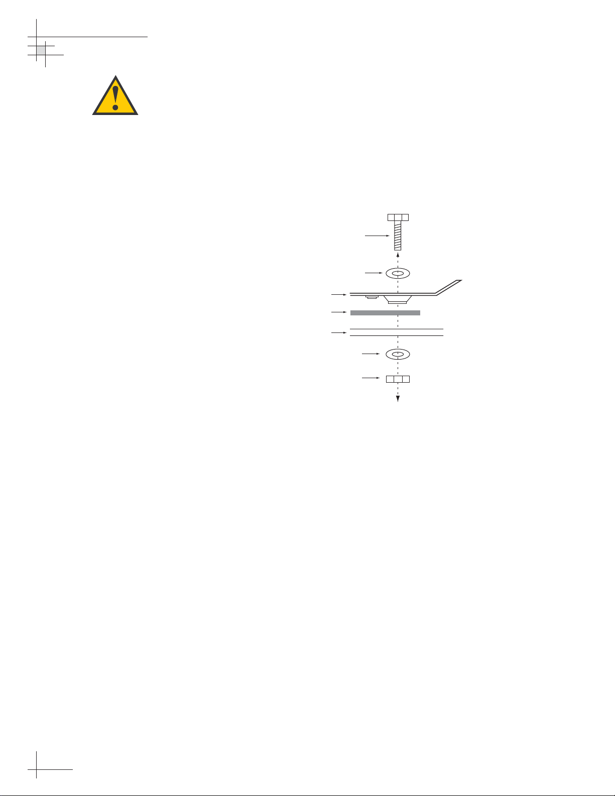
13. Place the antenna baseplate over the holes drilled
in the foundation, ensuring the “Forward” label
(shown in Figure 2-6) points toward the bow.
14. At each of the four baseplate mounting holes,
place a
1
⁄4" flat washer on a 1⁄4"-20 bolt and insert the
bolt into the hole from above, as shown in
Figure 2-8. Carefully rotate the azimuth
mechanism plate to expose all four mounting
holes.
15. Apply a
1
⁄4" flat washer and 1⁄4"-20 lock nut from
below, as shown in Figure 2-8.
16. Tighten securely (but do not overtighten) until the
foam seal is compressed as far as it will go and all
four feet are bottomed against the mounting
surface.
17. If you are installing a European system:
Leave the radome off for now; you will install it
later.
If you are installing a North American system:
Place the radome over the baseplate. Align the
three radome screw holes with the baseplate nut
holders, insert the #10-24 screws and tighten.
Install a protective plastic screw cap from the
kitpack over each screw.
Figure 2-8
Bolting the Antenna Unit to
the Deck (Side View)
When rotating the azimuth
mechanism by hand, go slowly.
Hitting the mechanical stops with
excessive force will damage the
azimuth limit switch.
54-0147
18
TracVision G4 Technical Manual
Bolt
Flat Washer
Antenna Unit Base
Foam Seal
Deck
Flat Washer
Lock Nut
Page 24
Installation
54-0147
19
2.3 Mounting the GyroTrac Sensor
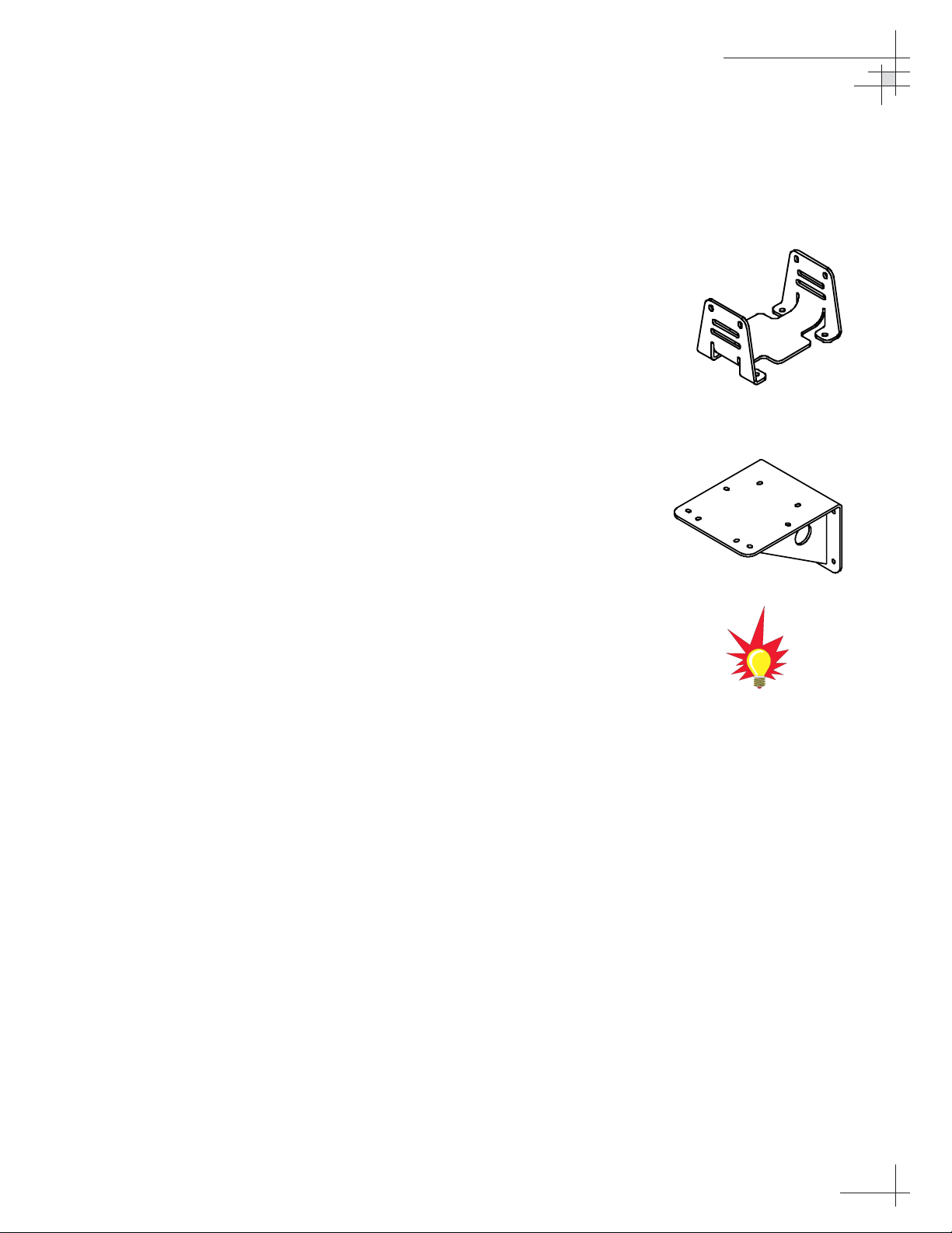
GyroTrac comes with the following two mounting brackets:
Horizontal Sensor Bracket
Attaches directly to the sensor module housing
and must be used in all mounting arrangements
Vertical Sensor Bracket
For mounting the sensor to a vertical surface
These two brackets should enable you to place the sensor module
as level as possible. If you are unable to place the sensor module
in a level arrangement, refer to “Entering Gyro Offset Values” on
page 75 to compensate for the offset.
To mount the GyroTrac sensor, choose either of the following
options:
Option 1 - Mounting the Sensor to a Horizontal Surface
Option 2 - Mounting the Sensor to a Vertical Surface
The following sections describe how to mount the sensor for both
of these options.
Figure 2-9
Horizontal Sensor Bracket
Figure 2-10
Vertical Sensor Bracket
Be sure to follow the guidelines in
“Choosing the Best Location for the
GyroTrac Sensor” on page 14.
Page 25
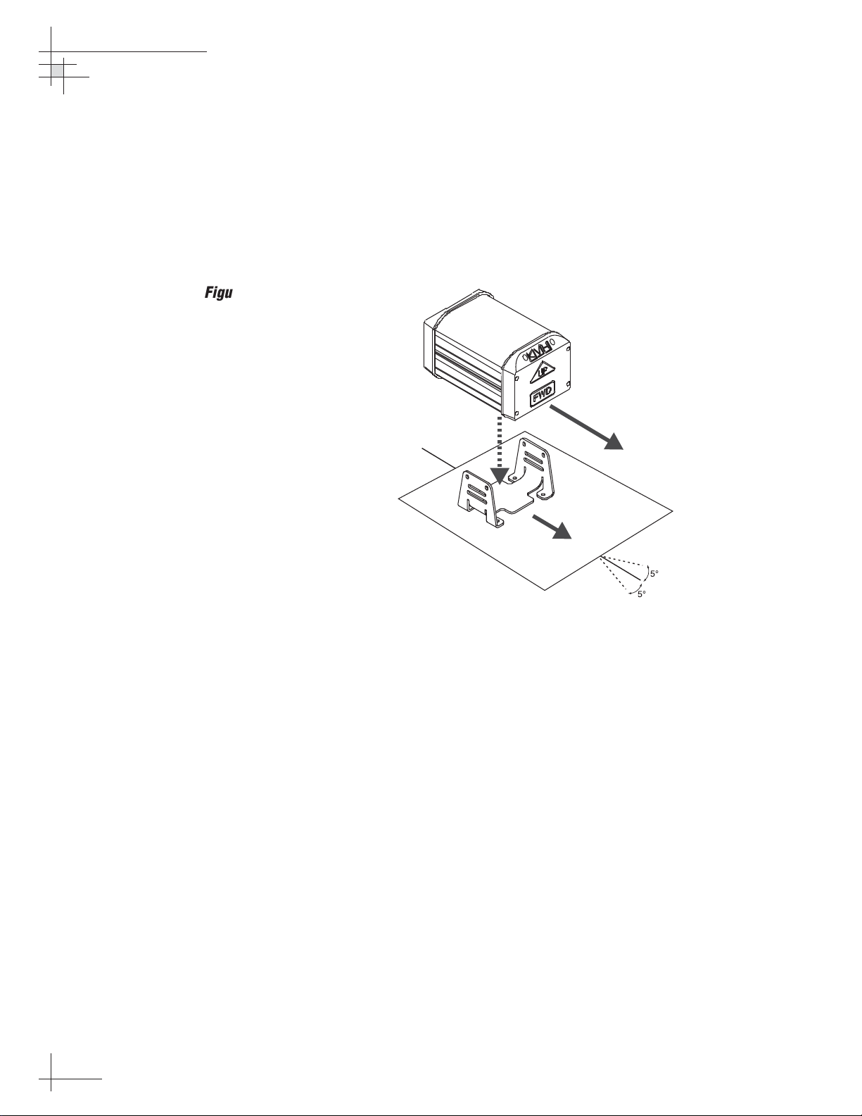
Option 1 - Mounting the Sensor to a Horizontal Surface
1. Choose a mounting location based upon the
guidelines in “Choosing the Best Location for the
GyroTrac Sensor” on page 14.
2. Orient the sensor so that the forward reference on
the end cap is pointed forward and is parallel to
the vessel’s fore-and-aft axis (to ±5°). The proper
orientation is illustrated in Figure 2-11.
3. Position the horizontal sensor bracket so that the
sensor module will be properly oriented when
placed in the bracket.
4. Using the holes in the bracket feet as a template,
mark locations for the four mounting screws.
Center punch and drill the four holes with a
1
⁄8"
(3.5 mm) bit. Reposition the bracket over the
mounting holes.
Figure 2-11
Proper Orientation of
the Sensor Module
54-0147
20
TracVision G4 Technical Manual
TOWARD BOW
5¡
5¡
Page 26
Installation
54-0147
21
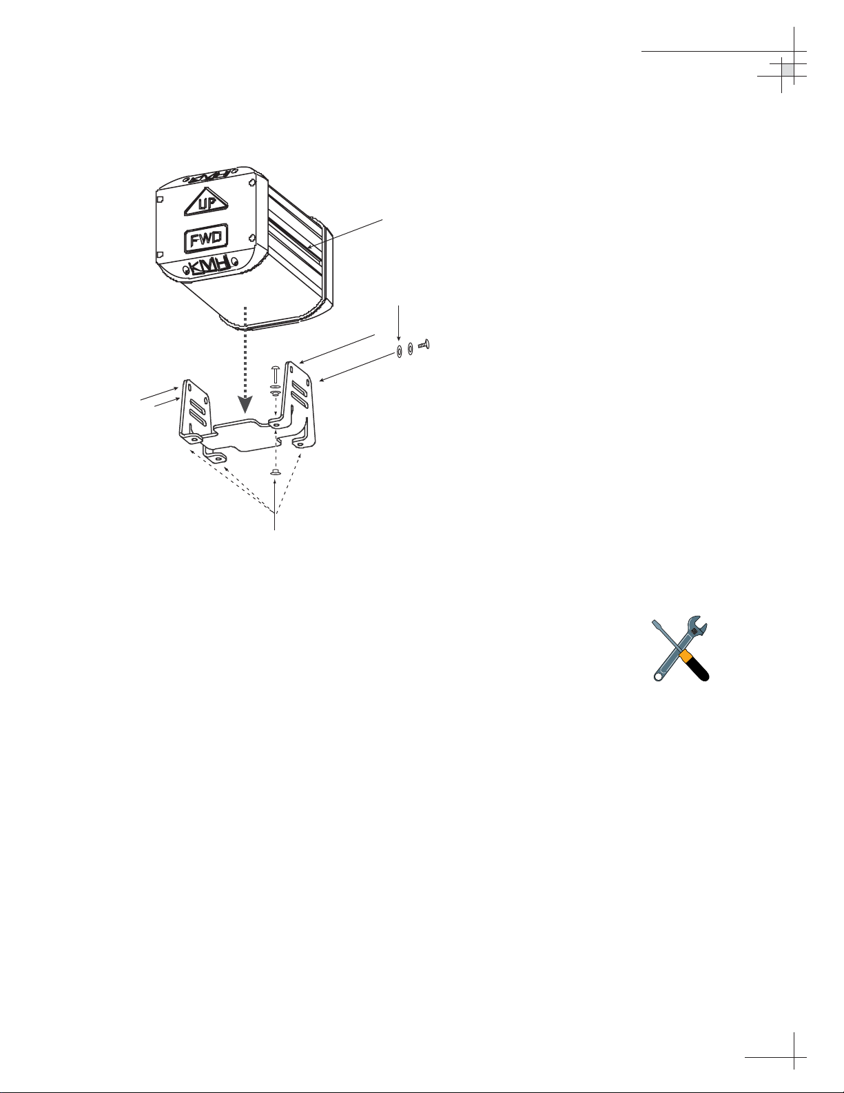
5. Insert #8 fiber washers into the mounting bracket’s
four mounting holes on both sides of the
mounting bracket (see Figure 2-12).
6. Insert #8 flat washers and #8 Phillips screws into
the mounting bracket’s four mounting holes from
above. Secure the bracket to the mounting surface.
7. Place the sensor module in the bracket with the
proper orientation (up/forward).
8. Thread #10-32 screws through lock washers, flat
washers, and bracket, and then into the captive
extrusion T-nuts within the sensor module
housing, as shown in Figure 2-12.
Figure 2-12
Securing the Sensor Module and
the Horizontal Sensor Bracket
Should you ever need to replace
the #10-32 screws used to secure
the housing to the bracket, the
screws must be no longer than 3⁄8"
(10 mm) to avoid damaging the
housing.
T-nuts contained within
sensor housing track
Flat washer, lock washer,
and #10 screw
#8 screw, flat washer,
and 2 fiber washers
Page 27
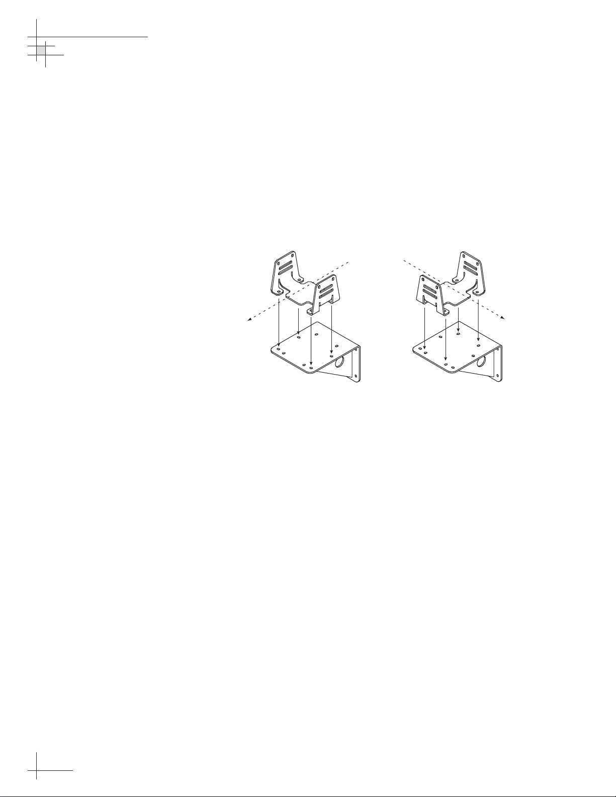
Option 2 - Mounting the Sensor to a Vertical Surface
1. Choose a mounting location based upon the
guidelines in “Choosing the Best Location for the
GyroTrac Sensor” on page 14.
2. The module must be oriented so that the forward
reference on the end cap is pointed forward and
parallel to the vessel’s fore-and-aft axis (see
Figure 2-11 on page 20). The brackets are designed
so that the sensor module may be mounted
perpendicular or parallel to the mounting surface,
as pictured in Figure 2-13.
3. The module must be level with the vessel’s deck.
You may fine-tune this placement using the
ADCU’s pitch and roll data. Adjust the brackets so
that the pitch and roll are 0 (zero) when the vessel
is docked and under normal load.
4. When choosing a location for the unit, make
certain that there is sufficient overhead clearance
for both brackets and the sensor module.
5. Using the holes in the vertical sensor bracket as a
template, mark locations for the four mounting
screws. Center punch and drill the four holes with
a
1
⁄8" (3.5 mm) bit.
54-0147
22
TracVision G4 Technical Manual
Figure 2-13
Bracket Orientations
Vessel
Centerline
OR
Vessel
Centerline
Page 28
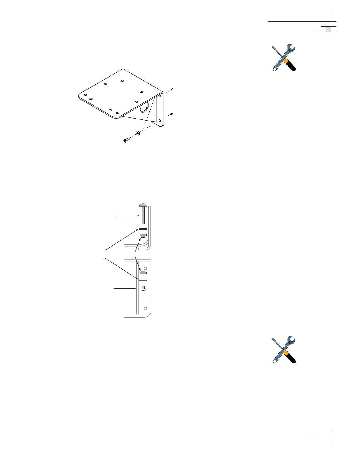
6. Secure the vertical sensor bracket to the mounting
surface with #8 Phillips screws and flat washers
(see Figure 2-14).
7. Position the horizontal sensor bracket over the
mounting holes in the vertical sensor bracket, as
shown in Figure 2-13.
8. Insert fiber washers into both sides of the
mounting brackets, as shown in Figure 2-15.
9. Insert #8 flat washers and #8-32 Phillips screws
into the horizontal bracket’s mounting holes from
above and through the vertical bracket. Secure in
place with #8 self-locking nuts and flat washers.
10. Place the sensor module in the horizontal bracket
with the proper orientation (up/forward).
11. Thread #10-32 machine screws through lock
washers, flat washers, and bracket, and then into
the captive extrusion T-nuts within the sensor
module housing, as shown in Figure 2-12.
Installation
54-0147
23
Figure 2-15
Securing the Horizontal Bracket
to the Vertical Bracket
Figure 2-14
Mounting the Vertical
Sensor Bracket
Should you ever need to replace
the #10-32 screws used to secure
the housing to the bracket, the
screws must be no longer than 3⁄8"
(10 mm) to avoid damaging the
housing.
If you do not use the supplied #8
screws, be sure to use equivalent
hardware that ensures secure
mounting and minimum vibration.
#8 screw and washer
#8 Pan Head Screw
Horizontal
Bracket
#8 Flat Washer Fiber Washer
#8 Self-locking Nut
Vertical
Bracket
Page 29
2.4 Mounting the ADCU
Mount the ADCU using either of the following options:
Option 1 - Velcro Fastening on a Horizontal Surface
Option 2 - Flush-mounting
The following sections describe how to mount the sensor for both
of these options.
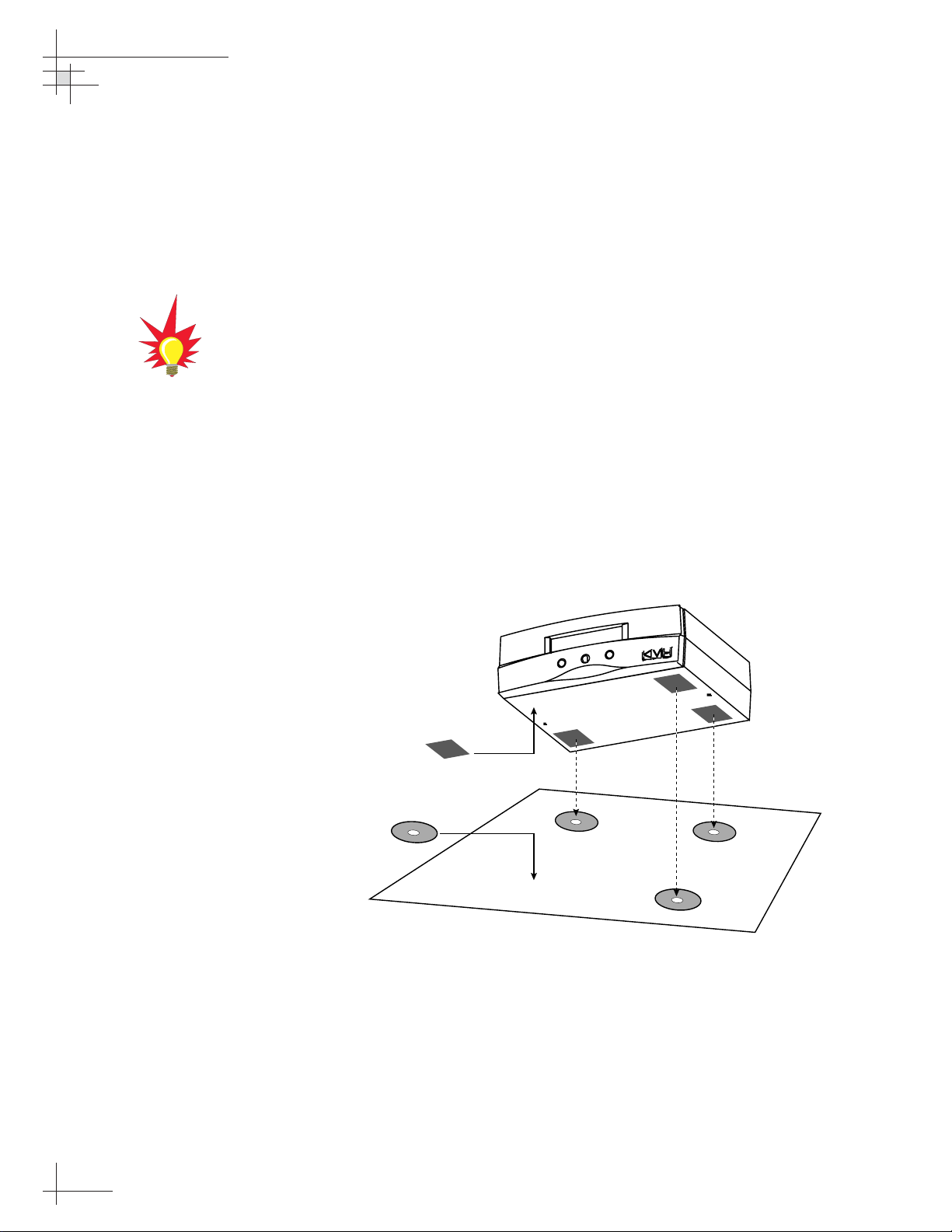
Option 1 - Velcro Fastening on a Horizontal Surface
1. Choose a location based upon the guidelines in
“Choosing the Best Location for the ADCU” on
page 14.
2. Remove the four squares of Velcro fabric from the
kitpack. Clean the bottom of the housing with a
mild detergent and water to remove oils, etc. Peel
the protective backing from the squares and apply
them to the bottom of the housing at each of the
four corners (see Figure 2-16).
3. Position the four Velcro hook disks where the
ADCU will be mounted. Drill screw holes for the
disks and secure in place with the #4-24 screws
supplied in the kitpack.
4. Press the ADCU firmly into place so that the loop
material engages the hook disks.
54-0147
24
TracVision G4 Technical Manual
When choosing a location, take into
account the space required to
route, position, and strain-relieve all
cables that will be attached to the
back of the ADCU. Directions for
proper wiring are presented in
Section 2.6, “Wiring the ADCU” on
page 29.
Figure 2-16
Mounting the ADCU with
Velcro Attachments
Fabric Strips
Hook Disks
Page 30
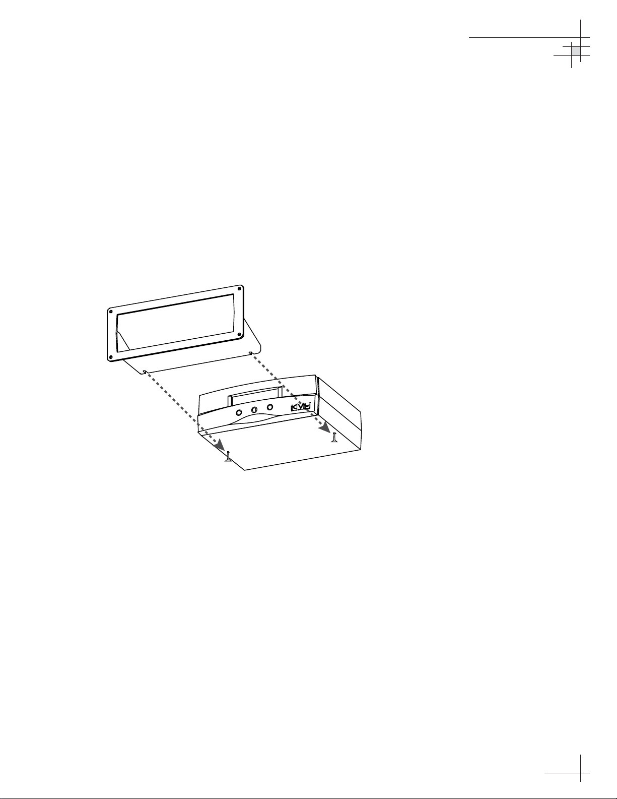
Option 2 - Flush-mounting
1. Choose a location based upon the guidelines in
“Choosing the Best Location for the ADCU” on
page 14.
2. A template has been provided in Appendix C on
page 129 as a guide to mark and cut the proper
hole for the flush mount bracket. Cut the hole and
make certain the bracket and ADCU will fit easily.
3. Attach the flush mount bracket to the ADCU by
loosening the two screws on the underside of the
ADCU. Slide the flush mount bracket backward
over the ADCU until the two notches meet the
screws as shown in Figure 2-17.
4. Tighten the screws to secure the ADCU to the
bracket.
5. After completing the wiring described in
Section 2.6, “Wiring the ADCU,” insert the ADCU
and bracket into the hole and secure the unit to the
mounting surface with the #8 (black) screws and
#8 washers supplied in the kitpack.
Installation
54-0147
25
Figure 2-17
Securing the ADCU to the
Flush Mount Bracket
Page 31

2.5 Connecting the IRD(s)
For the TracVision system to work, you must connect the
following cables to your satellite TV receiver(s) (IRDs):
• RF Cable
• Ground Wire
Connecting the RF Cable(s)
Each RF cable must be an RG-11 (75 ohms) or RG-6 (75 ohms)
cable fitted with F-type connectors. The RF cable(s) should
already be connected to the antenna baseplate (see Step 12 of
Section 2.2., “Mounting the TracVision Antenna” on page 17). The
following sections explain how to connect the RF cable(s) to your
IRD(s).
To connect the TracVision antenna to your IRD(s), choose one of
the following configurations (based on the number of IRDs you
will connect to the antenna):
Option 1 - Connecting One IRD
Option 2 - Connecting Two IRDs
Option 3 - Connecting Three or More IRDs
(North American systems only)
Option 1 - Connecting One IRD
One end of the RF cable should already be connected to the plug
labeled “RF1” on the base of the TracVision antenna. Connect the
other end of the RF1 cable to the IRD plug labeled “LNB,”
“ANT/SAT,” or “SATELLITE IN.”
Option 2 - Connecting Two IRDs
Two RF cables should already be connected to the plugs labeled
“RF1” and “RF2” on the base of the TracVision antenna. Connect
the other ends of these RF cables to the plug labeled “LNB,”
“ANT/SAT,” or “SATELLITE IN” on the two IRDs.
The IRD that is connected to the RF1 cable controls which
satellite the antenna is tracking. The IRD connected to RF2 can
select different channels on that satellite but not change the
satellite selection itself.
54-0147
26
TracVision G4 Technical Manual
For instructions on RF wiring for
TracNet, please refer to the
TracNet
Owner’s Manual
or
Technical
Manual
.
Page 32

Option 3 - Connecting Three or More IRDs
(North American Systems only)
To connect three or four IRDs to the TracVision antenna, you will
need to install an active multiswitch (Channel Master model
6214IFD or equivalent) between the antenna and the IRDs. Two
RF cables should already be connected to the plugs labeled “RF1”
and “RF2” on the base of the TracVision antenna. Figure 2-18
shows a typical wiring arrangement for three or four IRDs.
Mount the multiswitch unit in accordance with the
manufacturer’s instruction sheet.
1. Connect the RF cable labeled "RF1" to the
multiswitch input labeled "LNB RHCP +13V.”
2. Connect the RF cable labeled “RF2” to the
multiswitch input labeled "LNB LHCP +18V.”
3. Connect the multiswitch outputs to individual IRD
inputs. Use RG-6 cable with F-type connectors for
all RF connections. Terminate all unused output
connectors with 75 ohm DC blocks (Channel
Master #7184, Radio Shack #15-1259 or equivalent).
Installation
54-0147
27
Figure 2-18
Single Multiswitch Installation
(North American systems only)
The use of an active multiswitch will
interfere with the 22 KHz tone sent
by DIRECTV DSS Plus™IRDs to
the antenna. As a result, the
antenna will not receive the signal
to change satellites when you
change channels using your
DIRECTV DSS Plus remote. You
will need to use the ADCU front
panel buttons to switch between
satellites.
Due to the signal polarization in
European satellites, the use of a
multiswitch will result in a loss of
signal and less than optimal
operation with TracVision G4
systems used in Europe.
TracVision Antenna Baseplate
DC Power
IRD #1
RF1
RF2
DC In RHCP
Out 1 Out 2 Out 3 Out 4
+13v
IRD #2 IRD #3
VHF/UHF LHCP
Multiswitch
Powe r
Data
+18v
IRD #4
Page 33

Multiple Multiswitch Installation
If you need to connect more than four IRDs to the TracVision
antenna, you may carry out a multiple multiswitch installation,
as shown in Figure 2-19.
Connecting the IRD Ground Wire
A grounding wire has been provided to connect your IRD to a
suitable ground. Attach the grounding wire to any suitable screw
on the rear panel of the IRD with a good contact with the IRD
chassis. The other end should be connected to a suitable ground,
ideally to the ADCU ground terminal (route the ground wire to the
ADCU and leave unconnected for now). Each IRD that you connect
to the TracVision system should have a similar ground
connection.
If you are using a multiswitch, you can ground the multiswitch instead
of the individual IRDs.
54-0147
28
TracVision G4 Technical Manual
Figure 2-19
Multiple Multiswitch Installation
(North American systems only)
Be sure to connect a ground cable
from each IRD to a suitable ground,
ideally the ADCU ground terminal.
TracVision Antenna Baseplate
DC Power
RF1
RF2
RF Splitters/
Power Dividers
Powe r
Data
DC In RHCP
Out 1 Out 2 Out 3 Out 4
IRD #1
IRD #2 IRD #3
+13v
Multiswitch
VHF/UHF LHCP
+18v
IRD #4
DC Power
DC In RHCP
Out 1 Out 2 Out 3 Out 4
IRD #5 IRD #6 IRD #8IRD #7
+13v
Multiswitch
VHF/UHF LHCP
+18v
Page 34

2.6 Wiring the ADCU
All other wiring for the TracVision system connects at the rear
panel of the ADCU. Included in the GyroTrac kitpack are five
terminal strip connectors with terminal connectors numbered 1
through 60 (see Figure 2-20). You will connect all wires to these
terminal strip connectors first, then you will insert the connectors
into the rear panel of the ADCU.
For the TracVision system to work, you must wire the following
cables to the ADCU:
• Antenna Data Cable
• Antenna Power Cable (unless you are connecting
antenna power to its own circuit)
• GyroTrac Sensor Cable
• Vessel Power Cable
• IRD Ground Cable(s)
You may also connect other external devices, such as an
autopilot, plotter, remote display, or GPS, to the ADCU.
Figure 2-21 on the following page shows all available connections
to the ADCU.
Installation
54-0147
29
Figure 2-20
Terminal Strip Connectors
Connect all wires to the terminal
strip connectors first.
DO NOT
attach the terminal strip connectors
to the ADCU until you have
completed and verified all wiring.
Red Label
Yellow Label
3738
39
40
4647
5859
60
5354555657
4950
51
52
48
4142434445
12
11
10
9
87
6
5
4
3
2
1
13
22
21
20
19
18
17
16
15
14
Blue Label
Green Label
2423
25
3029282726
34
33
32
31
White Label
36
35
Page 35

54-0147
30
TracVision G4 Technical Manual
n
Figure 2-21
ADCU Wiring
SENSOR DATA FEED
(to Antenna)
Data Cable
TRACVISION PORT
(to/from Antenna)
Data Cable
SHIP’S POWER
(11-16 VDC)
IRD Ground Wire (to IRD)
SERIAL PORT #1: RS-422
(NMEA, Cetrek, KVH Data)
TXD- (Green/White)
TXD+ (White/Green)
Power In (Red)
Ground In (Black)
4800 baud
48 47 383940414243 37444546
DSS Ground (White/Orange)
DSS TXD (Gray/White)
DSS RXD (White/Gray)
NOT USED
60 59 505152535455 49565758
12 1110987612543
KVH Display Power
TX1A(+)
TX1B(-)
13 14 232221201918 24171615
Ground
NOT USED
Red Label
Yellow Label
Green Label
Blue Label
Antenna Ground (Black)
Antenna Power (Red)
+11-16 VDC
PC RXD (Orange/White)
PC TXD (White/Brown)
PC Ground (Brown/White)
GTX- (White/Blue)
GTX+ (Blue/White)
N/C
Sine
Sine (inverted)
Cosine
Cosine (inverted)
Ref
Ground
TRACVISION
POWER
(to Antenna)
Power Cable
PC TO ANTENNA
DATA LINES
Data Cable
GPS NMEA (to Anten
Data Cable
SINE/COSINE
(3-wire or 4-wire)
Refer to "Connecting the
Sine/Cosine Interface" for
complete intructions
Ground (White/Green)
GYROTRAC
SENSOR MODULE
SERIAL PORT #3: RS-422
(NMEA, Cetrek, KVH Data)
Unavailable with TracVision G6.
To modify, refer to "Selecting
TracVision or GyroTrac-only
4800 or 9600 baud
Operations"
SERIAL PORT #2: RS-422
(NMEA, Cetrek, KVH Data)
4800 or 9600 baud
TX(+) (White/Blue)
TX(-) (Blue/White)
RX(-) (White/Orange)
RX(+) (Orange/White)
+12v (Green/White)
Ground
TX3B(-)
TX3A(+)
25 26 353433323130 36292827
Ground
TX2B(-)
TX2A(+)
White Label
TX1B(-)
Ground
Shift L
Ground
GPS A+
GPS B-
KVH Display Power
TX1A(+)
Data H
Data L
Ground
Shift H
GPS or SHIP’S GYRO
NMEA DATA INPUT
(RS-422 @ 4800 bps 8.N.1)
Pass-through Duplicate of
SERIAL PORT #1: RS-422
4800 baud
FURUNO
DATA
Page 36

Tips for Safe and Successful Wiring
• When inserting a wire into a terminal connector,
make certain that the wire insulation is not
pinched in the connector.
• After inserting and securing wire, tug gently to
ensure that the connection is solid.
• Position cables behind the ADCU so that they
connect neatly to the terminal strips.
• Do not tin (solder) the wire ends.
• Each cable provided with the TracVision G4
should be routed and dressed before terminating
at the ADCU. The antenna data and power cable
wires may be trimmed to desired length. However,
be sure to cut back the drain wire (shield); do
NOT connect the drain wire to anything.
Connecting the Antenna Data Cable
Connect the antenna data cable to the red and yellow ADCU
terminal strip connectors as shown in Figure 2-22.
Installation
54-0147
31
A comprehensive wiring diagram of
the entire TracVision G4 system
has been provided for technical
reference in
Appendix D on
page 131.A color quick reference
guide to wiring the
TracVision G4 is also provided
on the inside front cover of this
manual.
Figure 2-22
Antenna Data Cable
to ADCU Wiring
Cut back any unused wires from
the Data Cable.
Do
NOT
connect the antenna data
cable’s drain wire (shield).
Green/White
White/Green
48 47 383940414243 37444546
Red Label
Orange/White
White/Orange
Gray/White
White/Gray
60 59 505152535455 49565758
Yellow Label
White/Brown
Brown/White
White/Blue
Blue/White
Page 37

Connecting the Antenna Power Cable
For single-switch convenience, the ADCU has been designed to
serve as a junction box between ship’s power and the antenna
unit. Connect the antenna power cable to the red ADCU terminal
strip connector as shown in Figure 2-23.
Alternate Method of Providing Power to the Antenna
(Optional)
Rather than using the ADCU as its power source, the antenna
unit can be connected directly to a separate 5-amp switch and
breaker if such a configuration is more convenient or if the
ADCU is placed more than 50 ft (15 m) from the antenna unit.
For example, this configuration would be preferred if you needed
to be able to turn off the antenna while keeping the GyroTrac
powered on.
If the power cable is longer than 50 ft (15 m), be sure to verify the
voltage at the antenna to ensure that there is sufficient power to
drive the antenna under load (11-16 VDC). If not, carefully
increase the voltage to the antenna unit to compensate for any
drop in power over the length of the cable and ensure that the
voltage reaching the antenna unit is between 11 and 16 VDC.
Do NOT connect the antenna to vessel power until all other
wiring is completed. Also, be sure to follow the same power
wiring guidelines provided in “Connecting the ADCU to Vessel
Power” on page 37.
54-0147
32
TracVision G4 Technical Manual
Figure 2-23
Antenna Power Cable
to ADCU Wiring
The antenna unit’s power cable
connector cannot accept cables
larger than 14 AWG (1.5 mm2).
Black
Red
48 47 383940414243 37444546
Red Label
Page 38

Connecting the GyroTrac Sensor Cable
1. Connect the connectorized end of the sensor cable
to the GyroTrac sensor module. Twist until locked
in place.
2. Connect the other end of the sensor cable to the
blue ADCU terminal strip connector as shown in
Figure 2-25.
Installation
54-0147
33
Figure 2-24
GyroTrac Sensor Connector
Figure 2-25
Sensor Cable to ADCU Wiring
Sensor Cable
Connector
Blue Label
13 14 232221201918 24171615
White/Green
White/Blue
Blue/White
White/Orange
Orange/White
Green/White
Page 39

Connecting External Devices to the ADCU
(Optional)
GyroTrac can be integrated with many types of onboard
equipment, including autopilots, radars, remote displays,
plotters, global positioning systems (GPS), and computers. All
connections between the ADCU and external devices are made at
the terminal strip connectors located on the rear of the ADCU.
Follow these guidelines when wiring additional equipment to the
ADCU:
• Make certain any additional equipment complies
with NMEA Standard 2.2.
• Data conductor wire should be minimum 18 AWG
(0.75 mm
2
), twisted pair, stranded, tinned marine
cable.
• Do not use cables with a wire diameter larger than
12 AWG (2.5 mm
2
), as this is the largest size the
ADCU connector plugs can accept.
• The cable provided with the optional KVH
rotating card display is fully compatible with
GyroTrac requirements. Note that cables to other
external devices should follow the manufacturer’s
recommendations.
• For power cable specifications, refer to Table 2-2
on page 10.
As noted in Figure 2-21 on page 30, the output for Serial Ports 2
and 3 can vary from 4800 baud to 9600 baud. This is determined
automatically based upon the selected output. Serial Port 1
provides 4800 baud output only.
When the TracVision G4 antenna is connected to the GyroTrac
system, GyroTrac Serial Port 3 will not be able to provide output
to other equipment. Serial Port 3 will only provide outputs if the
antenna unit is disconnected from the ADCU and GyroTrac is
configured to operate as a stand-alone system as described in
“Selecting TracVision or GyroTrac-only Operations” on page 76.
Connecting the Rotating Card Display (Optional)
For complete instructions on properly wiring the optional
rotating card display, refer to Appendix E on page 135.
54-0147
34
TracVision G4 Technical Manual
If the ADCU is receiving data from
a ship’s gyro, all compass outputs
are automatically configured as
True North and cannot be set to
Magnetic.
Page 40

Connecting the Sine/Cosine Interface
(Optional)
The GyroTrac ADCU sine/cosine interface provides the following
outputs:
• sine
• cosine
• inverse sine
• inverse cosine
• reference voltage
Because the reference voltage is a reference output, not an input,
connecting this output to another reference output from an
autopilot or other system will cause problems.
In this case, connect the following wires from the autopilot (or
other system) to the green ADCU terminal strip connector:
Autopilot/Other System Wire Terminal Connector
Sine 12
Cosine 10
Internal Power Ground 7
(not chassis ground!)
Reference (INPUT) 8 (KVH Output)
DO NOT connect the autopilot or other system to the ADCU reference
output (ADCU terminal 8) if the autopilot has its own internal
reference. Review the user’s manual for the selected equipment.
Installation
54-0147
35
Table 2-6
GyroTrac/Autopilot Sine/Cosine
Wiring Arrangement
Before connecting the Autopilot
internal ground to ADCU terminal 7,
use a low impedance voltmeter to
make certain that there is no DC
voltage between the two terminals.
A DC surge could damage one or
both systems.
The sine/cosine reference voltage is
an OUTPUT, not an INPUT.
Connecting this output to the
reference output for an autopilot or
other system can cause problems.
This section explains how to resolve
most issues.
Figure 2-26
Sine/Cosine ADCU Wiring
Green Label
12 1110987612543
Sine
Sine (inverted)
Cosine
Cosine (inverted)
Ref
Ground
Page 41

To adjust the GyroTrac reference to match the reference of the
autopilot (or other system), connect a voltmeter to GyroTrac
ADCU terminal (#8) and the reference terminal of the autopilot
(or other system). Adjust the GyroTrac reference voltage as
described in “Setting the Sine/Cosine Data Output” on page 69 until
the voltmeter indicates 0 VDC.
The sine/cosine interface should now operate with optimal
precision.
Connecting GPS for True North Capability
(Optional)
GyroTrac is capable of determining true north that is accurate,
under most conditions, to within ±1º. This capability requires a
GPS data input to the GyroTrac
NMEA sentences from the GPS must contain one or all of the
following sentences: VTG, VHW, or BWC. The sentence structure
must comply with the NMEA 0183 V2.20 standard and run at
4800 bps 8.N.1.
As illustrated in Figure 2-27 and the GyroTrac wiring quick
reference guide on the back cover of this manual, GPS interface
cables connect to the blue ADCU terminal strip connector at
terminals 23 and 24. Refer to your GPS user manual for the
correct NMEA data out configuration.
54-0147
36
TracVision G4 Technical Manual
When the vessel is stationary,
certain GPS models may not output
the data required for GyroTrac to
determine true north.
Figure 2-27
GPS to ADCU Wiring
Blue Label
13 14 232221201918 24171615
GPS A+
GPS B-
Page 42

Connecting the ADCU to Vessel Power
Short circuits may result in severe electrical shock or burns. Turn
off vessel power and test the circuit to ensure that no power is
present before connecting any power cables. Do NOT reapply
power until all system wiring is completed and all terminal
strip connectors are installed on the ADCU rear panel, as
described in “Connecting the Terminal Strip Connectors to the
ADCU” on page 38.
The TracVision G4 system requires an 11-16 VDC power input.
Since it does not have a dedicated power control (ON/OFF
switch), a quick-tripping circuit breaker or fuse should be
installed between vessel power and the ADCU. Circuit overload
protection should be rated for 5 amperes. For recommended
power cable specifications, refer to Table 2-2 on page 10.
If vessel power fluctuates widely or is noisy, a 12 VDC, 5-amp
AC/DC power supply or a wide-range DC/DC converter power
supply should be installed. Test the voltage and polarity before
making connections to vessel power.
Connect power to the green ADCU terminal strip connector as
shown in Figure 2-28. If the user-supplied power cable has a
drain or shielded wire, DO NOT connect the drain or shield to
either the ADCU or to ground.
Connecting the IRD Ground Wire
If you’ve routed an IRD ground wire to the ADCU (as
recommended in “Connecting the IRD Ground Wire” on page 28),
connect the wire to terminal 2 of the green ADCU terminal strip
connector (see Figure 2-28).
Installation
54-0147
37
Power supplied to the
TracVision G4
MUST NOT
exceed
16 VDC or the TracVision power
supply will suffer serious damage!
Figure 2-28
Vessel Power to ADCU Wiring
Before connecting the power cable,
turn off vessel power and test the
circuit to ensure that no power is
present.
Green Label
12 1110987612543
Vessel Power
(11-16 VDC)
IRD Ground Wire (to IRD)
Power In (Red)
Ground In (Black)
Page 43

Connecting the Terminal Strip Connectors to the ADCU
Now that you have connected all wires to the terminal strip
connectors, insert the connectors into the ADCU’s rear panel as
shown in Figure 2-29.
Be sure to attach the terminal strip connectors in their correct
positions, as shown in Figure 2-30.
54-0147
38
TracVision G4 Technical Manual
Figure 2-29
Attaching the Terminal Strips
to the ADCU
Figure 2-30
Proper Terminal Strip Order
Double-check all wiring. Be certain
to plug terminal strips into the
correct positions. If wiring is
incomplete or incorrect or the
terminal strips exchange positions,
serious electrical damage can
occur to the TracVision antenna
unit, the GyroTrac, and interfacing
electronics.
!$!#!"
!!!
!! ' &
% $
#
" !
"
!
'&%$#
'&%$#"!
Maintenance Port
Connectors 60 - 37
48 47 383940414243 3744454660 59 505152535455 49565758
Yellow Label Red Label
Green Label Blue Label White Label
12 1110987612543 13 14 232221201918 24171615 25 26 353433323130 36292827
Connectors 1 - 36
Page 44

Effective Strain Relief for ADCU Terminal Connections
Due to both the potential number of wires that connect to the
rear of the ADCU and the dynamic environment aboard ship, it is
critical that the terminal connections be properly strain-relieved
using tie-wraps (a number of which are included in the GyroTrac
kitpack).
Some things to consider when strain-relieving wires:
• There should be no tension on the wires
connecting to the terminal strips. Removing slack
is important, but the wires should not be taut.
• Leave enough slack in the wires to allow easy
access to the ADCU’s rear panel in case of future
software upgrades.
• If the cable is equipped with a ferrite, the ferrite
should be as close as possible to the terminal
connections.
• Strain-relieve wires and cables as close to the
ferrite as possible. A good arrangement includes a
tie-wrap behind the ferrite (on the side furthest
from the ADCU); an ideal design includes a tiewrap on either side of the ferrite.
Installation
54-0147
39
Figure 2-31
Examples of Effective
Strain Relief
Terminal Strip Connector
Good Strain-relief
Arrangement
Tie-wrap
Ferrite
Tie-wrap
Ideal Strain-relief
Arrangement
Page 45

2.7 Calibrating the Sensor
Every sensor module is calibrated at the factory in a perfectworld environment. However, hard and soft iron effects on your
vessel can distort the local magnetic field, causing errors in the
reported heading. These errors are minimized by mounting the
sensor module in a suitable location and are further removed by
GyroTrac’s autocalibration feature, which compensates for minor
magnetic distortions.
After installing the GyroTrac, you must calibrate the sensor as
described below and achieve a good calibration score to ensure the
highest degree of heading accuracy.
1. Select a calm day and a clear area. Avoid excessive
pitching and rolling, as this can distort the
calibration data.
2. Apply power to the ADCU and note your
approximate heading so that you will know when
you have completed a full circle.
3. Steer your vessel at a slow, steady speed through a
full circle that takes at least 2 minutes to complete.
(Try to time your turn so that it takes 30 seconds or
more to turn 90º.) After completing a full circle,
continue the process with a second circle. The
circles do not need to be perfectly round as long as
you make a complete 360º turn.
4. Once you have completed two full circles, your
GyroTrac should be calibrated. Check the
calibration score as described on the following
page.
You must calibrate the GyroTrac
sensor after installation so that it
can compensate for any magnetic
distortions.
The ADCU is equipped with a fuse
to protect against high-voltage
spikes. If the system is installed
correctly and power is available, but
the system is non-functional, refer
to
Section 4.3, “GyroTrac-specific
Issues” on page 97
for instructions
on checking and replacing the fuse.
54-0147
40
TracVision G4 Technical Manual
Page 46

Installation
54-0147
41
The Calibration Score
Each calibration results in a calibration score that is stored in the
system’s memory.
Accuracy (ACC)
The ACC data indicates the degree of accuracy the GyroTrac will
provide based on the quality of the last calibration. Table 2-7 lists
the five possible accuracy levels.
Magnetic Environment (MAGENV)
The MAGENV score (GOOD, OK, POOR, BAD) indicates the
quality of the installation location. If the quality is POOR or BAD,
the sensor module probably should be moved to a more
favorable magnetic environment.
Calibration Update Number (CAL #)
The CAL # indicates the number of times the sensor has been
calibrated. It is used primarily to verify whether a new
calibration has been accepted by the system.
Table 2-7
Possible Compass Accuracy Levels
A complete explanation of the
GyroTrac menus is provided in
Section 3, “Using the ADCU
Interface” on page 59.
Specifics
regarding calibration are provided
in
Section 3.6, “Control Compass
Mode” on page 77.
ACC Score Accuracy
<1º Better than 1º
<2º Better than 2º
<4º Better than 4º
<8º Better than 8º
BAD CAL Recalibrate
Figure 2-32
Sample Calibration Score Screen
For guidelines on finding a suitable
location, refer to
“Choosing the
Best Location for the GyroTrac
Sensor” on page 14.
Magnetic Environment
Accuracy
ACC MagEnv Cal#
CAL<1° GOOD 3
Calibration Update
Number
Page 47

54-0147
42
TracVision G4 Technical Manual
2.8 Activating/Programming the IRD
Before it can be used, your IRD must be activated and/or
programmed, as described below.
DIRECTV and DISH Network IRD Activation
KVH makes it easy to activate your DIRECTV or EchoStar (DISH
Network) IRD. Just call KVH at 1-888-584-4163 and ask for IRD
Activation (Monday - Friday, 8:30 a.m. - 5:00 p.m. EST). For other
options, please refer to the user manual that accompanied your
IRD.
Other IRD Activations
Please refer to the user manual that accompanied your IRD for
activation instructions.
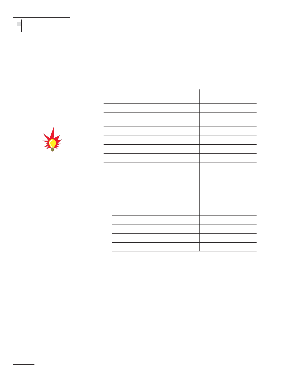
Programming European IRDs
Before the TracVision G4 system can be used in Europe, the IRD
must be programmed to receive signals from the selected DVB
satellite services. Programming is conducted using menu
selections displayed on the TV screen. Please refer to your IRD
owner’s manual for specific instructions.
Table 2-8 provides some key data for use when programming
the IRD.
Configuration Item Setting
Antenna Alternative 1 DiSEqC 1
Antenna Alternative 2 DiSEqC 2
LNB Frequency Universal
It is also important that the IRD’s settings for Antenna
Alternatives 1 and 2 match the ADCU’s installed satellite settings
as follows:
• Antenna Alternative 1 = Satellite A
• Antenna Alternative 2 = Satellite B
Section 2.9, “Installing Satellites Using the ADCU” on page 44
provides details on the satellite installation process.
Table 2-8
Key IRD Settings
When programming the IRD with
the antenna configuration data,
make certain that your choices for
Antenna Alternatives 1 and 2 match
those installed as Satellites A and
B during the Install Satellite
procedure detailed in
Section 2.9,
“Installing Satellites Using the
ADCU” on page 44.
Page 48

Installation
54-0147
43
Programming DSS Plus IRDs
If you are using multiple DSS Plus IRDs and intend to shift from
one satellite to another, only one of the IRDs can be configured as
a two-satellite receiver. All other IRDs must be configured as onesatellite receivers. The two-satellite IRD will determine which
satellite the antenna is tracking while the other receivers can
watch any channels available via that satellite. Refer to your IRD
owner’s manual for complete details on this process.
If you use an active multiswitch to
connect three or more IRDs, the
multiswitch will interfere with the
22 KHz tone sent by DIRECTV
DSS Plus™IRDs to the antenna. As
a result, the antenna will not
receive the signal to change
satellites when you change
channels using your DIRECTV DSS
Plus remote.
Page 49

54-0147
44
TracVision G4 Technical Manual
2.9 Installing Satellites Using
the ADCU
The TracVision G4 can track a variety of DVB-compatible and
DIRECTV (DSS) satellites. The system contains a preprogrammed
library of North American and European satellites. It also has
two open slots that you may use to program two additional
satellites of your choice. Tables 2-9 and 2-10 list the possible
satellite pairs. Two of these satellites may be selected to reside in
the system’s active memory as Satellites A and B.
The satellites listed in TracVision G4’s preprogrammed satellite
library will be sufficient for most users. However, if you wish to
install one or two satellites that are not in the library, skip to
“Programming User-defined Satellites” on page 47. After configuring
these user-defined satellites, return to the satellite installation
process in “Installing Your Selected Satellites” on page 45.
Table 2-9
Available Satellite Pairs
– North America
(North American LNB required)
Table 2-10
Available Satellite Pairs – Europe
(European LNB required)
DSS_101 DSS_119 Echo_61 Echo_110 Echo_119 Echo_148 Expressvu ExpressTV
DSS_101 ✓✓✓
DSS_119 ✓✓✓
Echo_61 ✓✓ ✓✓
Echo_110 ✓ ✓✓✓✓
Echo_119 ✓✓ ✓✓✓
Echo_148 ✓✓ ✓✓
Expressvu ✓✓✓✓✓✓ ✓
ExpressTV ✓✓✓✓✓✓✓
Astra 1 Astra 2N Astra 2S Hispasat Hotbird Sirius Thor
Astra 1 ✓✓ ✓✓
Astra 2N ✓✓
Astra 2S ✓✓
Hispasat
Hotbird ✓✓ ✓ ✓
Sirius ✓✓✓
Thor ✓
Page 50

Installation
54-0147
45
Installing Your Selected Satellites
To install your selected satellites as Satellite A and B, follow the
steps below.
1. Apply power to the ADCU.
2. Following the startup sequence, press the center
button until the “Control Antenna?” screen
appears.
3. Press the
ENTER button to access the Control
Antenna Mode.
4. Press the center button until the “Install Satellite?”
screen appears.
5. Follow the process shown in Figure 2-35 on the
following page to install your selected satellites. At
the end of the process, be sure to press the YES
button to restart the antenna.
Section 3, “Using the ADCU
Interface” on page 59
provides
complete details on the use of the
ADCU menus, including complete
antenna control details in
Section 3.8, “Control Antenna
Mode” on page 81.
Figure 2-33
Control Antenna Screen
Figure 2-34
Install Satellite Screen
Control antenna?
Enter Next Return
Install satellite?
Yes Next Return
Page 51

54-0147
46
TracVision G4 Technical Manual
Figure 2-35
Install Satellite Process
If a GPS is providing latitude and
longitude to TracVision G4, this
data will automatically be used in
the satellite installation process. In
this event, the Latitude/Longitude
menus will skip directly to “Restart
Antenna.”
Install Satellite?
Yes Next Return
Install A <SAT NAME>
Yes Next Cancel
Install B <SAT NAME>
Yes Next Cancel
Installing sats
Please wait
<SAT Name> and
<SAT NAME> installed
Proceed to "Setting Latitude
and Longitude"
Selecting NEXT will cycle
the display through all
available satellites
Selecting NEXT will cycle
the display through all
satellites that can be paired
with the selection for
Satellite A. If no satellite is
available for a pair or you
wish a single satellite
configuration, select NONE.
Refer to Tables 2-9 and
2-10 for available satellite
pairs.
Latitude: ##N
- Enter +
Longitude: ###E
- Enter +
Latitude: ##N
Longitude: ####E
Restart antenna?
Yes No
Restart
Antenna
System
Enter your latitude. Use the -/+
keys to select each number and
choose between NORTH and
SOUTH. Selecting ENTER will
cycle the display through each
digit and the direction option and
then launch the LONGITUDE
screen.
Enter your longitude. Use the -/+
keys to select each number and
choose between EAST and
WEST. Selecting ENTER will cycle
the display through each digit and
the direction option and then
display the selected latitude and
longitude.
Page 52

Installation
54-0147
47
Programming User-defined Satellites
The TracVision G4 satellite library has the capacity for two userdefined satellites in case you want to track a satellite that is not
currently preprogrammed in the library. User-defined satellites
can only be configured via the ADCU’s maintenance port. To
configure a user satellite, information about the satellite must be
provided, including:
• Satellite name
• Satellite position (longitude)
• Transponder information for each of the following
polarizations/frequencies:
- vertical high
- vertical low
- horizontal high
- horizontal low
OR
- right
- left
• Transponder information includes:
- frequency
- symbol rate
- FEC code
- network ID (in hexadecimal format)
This information can be obtained from your satellite service
provider or from a number of sites on the Internet, such as
www.satcodx.com.
How to tell the difference between
High and Low bands:
High: 11.700 - 12.750 GHz
Low: 10.700 - 11.700 GHz
For your reference, the satellite
configuration information for the
predefined satellites is available on
our web site at
www.kvh.com/
footprint
.
Page 53

54-0147
48
TracVision G4 Technical Manual
Connecting a PC to the ADCU Maintenance Port
To program your user-defined satellites into the TracVision G4
satellite library, you need to connect a PC to the ADCU’s
maintenance port. This procedure requires Windows
Hyperterminal (or other terminal emulation software, such as
PROCOMM). Use the settings appropriate to your application
and follow the steps below.
1. Connect one end of the PC data cable to
the DB9 maintenance port connector on the rear of
the ADCU. Connect the other end to the serial port
on your PC (a 9-pin/25-pin connector adapter may
be needed for some PCs).
2. Open the terminal emulation software and
establish the following settings:
• 9600 baud
• no parity
• 8 data bits
• 1 start bit
• 1 stop bit
• no flow control
3. Apply power to the TracVision G4 system and
allow the system to complete full initialization.
Data should be scrolling on the PC display to
identify any system problems detected. If no data
is seen, recheck your connections and the terminal
software setup for the correct COM port.
Figure 2-36
ADCU Maintenance Port
Maintenance
Port (DB9)
48 47 383940414243 3744454660 59 505152535455 49565758
12 1110987612543 13 14 232221201918 24171615 25 26 353433323130 36292827
Page 54

Installation
54-0147
49
Entering User-defined Satellite Data
To configure your user-defined satellites, follow the steps below.
1. Using your PC’s terminal emulation program, type
HALT<cr> (<cr> indicates a carriage return/ENTER
key). This command puts the antenna in Idle mode.
2. Enter the SATCONFIG parser command:
Command: SATCONFIG,USERX,YYY,Z,D,L<cr>
Where: X = 1 or 2 (satellite alternative)
YYY = longitude (0-180)
Z = E (East) or W (West)
D = decoding type (0 = test, 1 = DSS-A,
2 = DSS-B, 3 = DVB)
L = LNB polarization (C = circular, L = linear)
Function: configures one of the user-configurable satellites
with the longitude provided
Response: if valid entry, echoes the input data
if invalid entry, returns error message
3. Type @DEBUGON<cr> to enter DEBUG mode.
4. Enter the satellite’s transponder information:
Command: @SATCONFIG,X,N,F,S,C,ID,P,B,D<cr>
Where: @SATCONFIG = directs data to the RF Board
X = satellite location A or B
N = satellite table # (98 & 99 are slots for user-
defined satellites)
F = frequency in MHz (either 00000 or a range from
10700 - 12700)
S = the satellite transponder symbol rate in
Mbit/second (01000 - 29999)
C = the FEC code (e.g., 12, 23, 34, 56, 67, 78)
ID = the satellite network ID in hexidecimal format
(0x####)
P = the LNB polarization (V = vertical,
H = horizontal, R = right, L = left)
B = the LNB down conversion frequency (L = low,
H = high, U = USA)
D = decoding type (0 = test, 1 = DSS-A,
2 = DSS-B, 3 = DVB)
Table 2-12
Satellite Transponder
Data Sequence
Table 2-11
SATCONFIG Parser Command
Page 55

54-0147
50
TracVision G4 Technical Manual
5. Repeat Step 4 for each of the following
transponder categories:
• vertical high • vertical low
• horizontal high • horizontal low
OR
• right • left
TracVision G4 requires that the data fields for all
transponder categories be provided. If the selected
satellite does not have information for one or more of
the transponder categories, default information should
be entered in the fields as follows:
Transponder Data Default Value
Frequency 00000
Symbol Rate 27500
FEC Code the same value as provided for those
transponders with data
Network ID 0x0000
Polarity and Band whichever combinations are not
already provided
6. After entering all of the necessary information,
save the settings by typing
@SAVE,A<cr> (or B if
the data is for satellite User 2).
7. Type
ZAP<cr> to restart the antenna.
8. If you need to configure a second user-defined
satellite, repeat this procedure starting with Step 1
to enter data for the USER2 satellite.
You have now added your user-defined satellite(s) to the
system’s satellite library. The first user-defined satellite you
configured is stored as USER1. If you configured a second
satellite, it is stored as USER2.
If you want the antenna to track one or both of these user-defined
satellites, you need to install it. To install a satellite, you can use
either the ADCU, as described in “Installing Your Selected
Satellites” on page 45, or you can use the SATINSTALL command,
as described on the following page.
Table 2-13
Satellite Transponder
Default Data
Page 56

Installation
54-0147
51
Installing User-defined Satellites via the Maintenance Port
1. Type HALT<cr> to put the antenna in Idle mode.
2. Enter the
SATINSTALL parser command:
Command: SATINSTALL,<sat_a_name><sat_b_name><cr>
Where: <sat_a_name> = the name of your choice for
Satellite A (for example: USER1)
<sat_b_name> = the name of your choice for
Satellite B (for example: USER2)
If you only want to install and track one satellite,
enter
NONE as the name of Satellite B.
3. Once you’ve assigned satellites as Satellite A and
Satellite B, you need to tell the antenna which of
the two satellites it should initially acquire and
track. This step should be performed the first time
a satellite is selected, allowing the system to
download the channel guide. To do so, enter the
following parser command:
Command: @L,A or B<cr>
Where: A = track Satellite A
B = track Satellite B
4. Type ZAP<cr> to restart the antenna.
Examples of the user-defined satellite configuration process are
provided for reference in the next two sections.
Page 57

54-0147
52
TracVision G4 Technical Manual
An Example of Configuring a User-defined Satellite (N. America)
The following is an example of configuring the fictional
YOURSAT 123 as the USER1 configured satellite. Prior to
configuring this satellite or any others, be certain to get the most
up-to-date information from one of the sources previously
discussed.
YOURSAT 123 at 122 West, DVB decoder, Circular Polarization LNB
Right
Frequency 12.225 GHz
Symbol Rate 20000
FEC Code 5/6
Network ID 4100(dec) = 0x1004
Left
Frequency 12.456 GHz
Symbol Rate 20000
FEC Code 5/6
Network ID 4100(dec) = 0x1004
Based on this information, the data entered via the PC would
look like this, assuming that YOURSAT 123 would be Satellite A:
HALT
SATCONFIG,USER1,122,W,3,C
@DEBUGON
@SATCONFIG,A,98,12225,20000,56,0x1004,R,U,3
@SATCONFIG,A,98,12456,20000,56,0x1004,L,U,3
@SAVE,A
ZAP
To install and start tracking the USER1 satellite, the following
additional data would be entered:
HALT
SATINSTALL USER1,NONE
@L,A
ZAP
Table 2-14
Sample Satellite Configuration
Data (North America)
Page 58

Installation
54-0147
53
An Example of Configuring a User-defined Satellite (Europe)
The following is an example of configuring the fictional
YOURSAT 123 as the USER1 configured satellite. Prior to
configuring this satellite or any others, be certain to get the most
up-to-date information from one of the sources previously
discussed.
Yoursat 123 at 7 West, DVB decoder, Linear Polarization LNB
Horizontal High
Frequency 11.966 GHz
Symbol Rate 27500
FEC Code 3/4
Network ID 2048(dec) = 0x0800
Vertical High
Frequency 11.823 GHz
Symbol Rate 27500
FEC Code 3/4
Network ID 2048(dec) = 0x0800
Vertical Low
No Data Listed
Horizontal Low
No Data Listed
Based on this information, the data entered via the PC would
look like this, assuming that YOURSAT 123 would be Satellite A:
HALT
SATCONFIG,USER1,7,W,3,L
@DEBUGON
@SATCONFIG,A,98,11966,27500,34,0x0800,H,H,3
@SATCONFIG,A,98,11823,27500,34,0x0800,V,H,3
@SATCONFIG,A,98,00000,27500,34,0x0000,V,L,3
@SATCONFIG,A,98,00000,27500,34,0x0000,H,L,3
@SAVE,A
ZAP
To install and start tracking the USER1 satellite, the following
additional data would be entered:
HALT
SATINSTALL USER1,NONE
@L,A
ZAP
Table 2-15
Sample Satellite Configuration
Data (Europe)
Page 59

54-0147
54
TracVision G4 Technical Manual
2.10 Setting the Skew Angle
(European Systems Only)
To optimize channel reception, the antenna’s LNB skew angle
must be adjusted. Refer to your satellite service provider for the
proper skew angle for your selected satellite service and
geographical location. You can also find the proper skew angle
from the ADCU, as long as a GPS is providing data to the ADCU
or the vessel’s correct latitude and longitude are entered into the
ADCU. Refer to “Antenna Status Data Screens” on page 80 for
details on viewing the ADCU-calculated skew value.
Adjusting the LNB Skew Angle
1. Turn off the power to the antenna unit.
2. If the radome is not already removed, remove the
radome and set it aside in a safe place.
3. Loosen the two wing screws securing the LNB
within the choke feed as illustrated in Figure 2-37.
4. Refer to the LNB skew angle labels on the end of
the LNB and on the LNB choke feed (shown in
Figure 2-38) and adjust the LNB as necessary to
match as closely as possible the skew angle
provided by your service provider or the ADCU.
5. Retighten the wing screws.
6. Reinstall the radome. Align the three radome
screw holes with the baseplate nut holders, insert
the #10-24 screws and tighten. Install a protective
plastic screw cap over each screw.
Figure 2-38
Skew Angle Labels
Figure 2-37
Adjusting the European
LNB Skew Angle
Skew Labels
Page 60

Installation
54-0147
55
2.11 Checking Out the System
Now that you’ve installed the TracVision G4, you need to verify
that the system functions properly. Check the system startup
routine to ensure that the system is operating within normal
parameters.
To view the startup routine, connect a PC to the ADCU’s
maintenance port. The diagnostics procedure requires Windows
Hyperterminal (or other terminal emulation software, such as
PROCOMM). Use the settings appropriate to your application.
1. Connect one end of the PC data cable to
the DB9 maintenance port connector on the rear of
the ADCU. Connect the other end to the serial port
on the PC (a 9-pin/25-pin connector adapter may
be needed for some PCs).
2. Open the terminal emulation software and
establish the following settings:
• 9600 baud
• no parity
• 8 data bits
• 1 start bit
• 1 stop bit
• no flow control
3. Apply power to the TracVision G4 system and
allow the system to complete full initialization.
Data should be scrolling on the PC display to
identify any system problems detected. If no data
is seen, recheck your connections and the terminal
software setup.
A sample startup sequence has
been provided in
Appendix F on
page 143
with the typical ranges
and responses for the
TracVision G4 during startup and
operation.
Figure 2-39
ADCU Maintenance Port
48 47 383940414243 3744454660 59 505152535455 49565758
12 1110987612543 13 14 232221201918 24171615 25 26 353433323130 36292827
Maintenance
Port (DB9)
Page 61

54-0147
56
TracVision G4 Technical Manual
4. After completing the review of the startup and
operational routines, turn on the IRD and television
and check the channels on the selected satellites.
For European systems, check both horizontally and
vertically polarized channels, if possible.
5. When all checks are completed, shut down the
system.
Be certain to fill out and submit the
warranty card to KVH to ensure
that your TracVision G4 is fully
covered under the 2-year parts and
1-year labor warranty.
Page 62

Installation
54-0147
57
2.12 Changing Geographic Location
If you move to a different geographic area, you will need to
modify your TracVision G4 system to receive satellite TV signals
in the new location. To begin receiving satellite signals in the new
area, perform the following steps.
Swap LNBs
To receive the proper satellite signals in the new geographic
location, your TracVision antenna must be equipped with the
appropriate LNB for that location. If moving to the U.S., you will
need to install a North American-style LNB; if moving to Europe,
you will need to install a European-style LNB. Table 2-16 lists the
part numbers for ordering these LNB options.
Part Name Part Number
European-style LNB 02-1278
North American-style LNB 02-0870
With the new part, you will receive a simple instruction sheet for
swapping the LNBs.
Install New Satellites
When you move to a new area, the list of available satellites
changes. If you’re moving to the U.S., you will need to choose a
new satellite pair from the list of available North American
satellites (see Table 2-9). If you’re moving to Europe, you will
need to choose a new satellite pair from the list of available
European satellites (see Table 2-10). For details on installing these
new satellites, refer to Section 2.9, “Installing Satellites Using the
ADCU” on page 44.
Replace the IRD
In order to receive satellite TV service in your new geographic
location, you will need to purchase an IRD designed for that
location. Refer to your satellite TV service provider for more
information.
Table 2-16
LNB Part Numbers
You may also need to replace your
television when changing
geographic location. In North
America, your TV must support the
NTSC video standard. In Europe,
your TV must support the PAL
video standard.
Page 63

Using the ADCU Interface
54-0147
59
3 – Using the ADCU
Interface
This section explains how to use all of the ADCU functions. You will use
the ADCU to operate, control, and monitor the TracVision G4 and
GyroTrac.
Contents
3.1 Startup and Self-test . . . . . . . . . . . . . . . . . . . . . . . . . . . . . . . . . . .61
3.2 Data Display and Accessing the Main Menu . . . . . . . . . . . . . . . . .63
3.3 Setup Display Mode . . . . . . . . . . . . . . . . . . . . . . . . . . . . . . . . . . .67
3.4 Set Data Outputs Mode . . . . . . . . . . . . . . . . . . . . . . . . . . . . . . . . .68
3.5 Set Configuration Mode . . . . . . . . . . . . . . . . . . . . . . . . . . . . . . . . .73
3.6 Control Compass Mode . . . . . . . . . . . . . . . . . . . . . . . . . . . . . . . . .77
3.7 Antenna Status Mode . . . . . . . . . . . . . . . . . . . . . . . . . . . . . . . . . .79
3.8 Control Antenna Mode . . . . . . . . . . . . . . . . . . . . . . . . . . . . . . . . . .81
Page 64

Using the ADCU Interface
54-0147
61
3.1 Startup and Self-test
1. Turn on the IRD and television.
2. If a GPS receiver is connected, ensure that it has
obtained an accurate position.
3. Apply operating power to the ADCU.
4. Wait while the system conducts a brief self-test
sequence. Test status messages are displayed on
the ADCU for approximately two seconds each.
If the self-testing routine detects faults in any of the first four selftests, the screen pictured in Figure 3-2 is displayed. Operation
halts at this point and the GyroTrac cannot operate. The unit
should be returned to your local authorized KVH dealer,
distributor, or service center.
Figure 3-1
Startup and Self-test Sequence
The absence of valid GPS data is
not a fault; the status message
merely indicates that valid GPS
data is not present and that those
navigation functions that use GPS
inputs are not available.
The GPS must be turned on first for
TracVision G4 to use the GPS
position data during initialization.
Figure 3-2
Startup Error Screen
KVH Industries Inc.
GyroTrac Rev. #.#.
System Testing
Microcontroller
system Testing
Memories
system Testing
Sine Cosine Circuit
system Testing
Gyroscope
No data from Gyro
System not running
system Testing
Global Position Sys
No GPS Data while
System powerup
* GyroTrac Config *
As a TV System
* GyroTrac Config *
As a GyroTrac System
" !#
"
!
Errors detected on
XXXXXXX
Page 65

TracVision Startup and Self-test Screens
When configured as a component of a TracVision system,
GyroTrac conducts a series of startup routines and self-tests to
verify antenna operation. The TracVision self-test status screens
are only displayed when the main data display is set to show the
antenna status information (as described in Section 3.3, “Setup
Display Mode” on page 67.
54-0147
62
TracVision G4 Technical Manual
Figure 3-3
TracVision G4 Startup Screens
Antenna initializing
Waiting for POS data
Init RF Controller
Waiting for POS data
Initial Ext Sensor
Waiting for POS data
Initial Antenna
###.#° ##.#° ####
Initial Rate Bias
###.#° ##.#° ####
** Search mode 1 **
###.#° ##.#° ####
** Search mode 2 **
###.#° ##.#° ####
** Search mode 3 **
###.#° ##.#° ####
Antenna is Tracking
###.#° ##.#° ####
Network ID Check
###.#° ##.#° ####
Tracking <SATNAME>
###.#° ##.#° ####
To Main Data Display
Page 66

3.2 Data Display and Accessing
the Main Menu
As soon as the self-test routine is completed, the LCD panel
shows one of five data displays selected in the Display Setup
Mode (described in Section 3.3, “Setup Display Mode” on page 67.
When any of the primary data displays are on screen, the soft
keys allow you to switch between the two installed satellites as
well as enter the Main Menu. The key functions and display
options are as follows:
Using the ADCU Interface
54-0147
63
Figure 3-4
Soft Key Functions and
Primary Data Displays
Primary Data Displays*
Magnetic Heading
###.#°
Pitch Roll Yaw
#.#° #.#° #.#°
Mag/Hdg Rate/Sec
#.#° #.#°
Lat: ##°
Long: ##°
Tracking <Sat Name>
###.#° ##.#° ####
* Variations on these displays are also presented in Figure 3-9.
Track Installed
Satellite A
Enter Main
Menu
Track Installed
Satellite B
Page 67

Main Menu
Pressing the center key will cycle the Main Menu through the
available functions as follows:
54-0147
64
TracVision G4 Technical Manual
Figure 3-5
Main Menu Functions
Select Installed Satellite A Select Installed Satellite B
Proceed to Section 3.3,
"Setup Display Mode"
(set data displayed on the LCD
during normal operation)
Proceed to Section 3.4,
"Set Data Outputs Mode"
(set type and format
of data outputs)
Proceed to Section 3.5,
"Set Configuration Mode"
(set heading reference source,
enter gyro offsets, reset to factory
defaults, and turn TV comm on/off)
Magnetic Heading
###.#°
Setup display type?
Enter Next Return
Setup data outputs?
Yes Next Return
Setup configuration?
Yes Next Return
Control Compass?
Yes Next Return
This menu will only appear
if the heading reference is
configured as INTERNAL.
Proceed to Section 3.6,
"Control Compass Mode"
(set calibration, read cal score, and
clear compass calibration)
Proceed to Section 3.7,
"Antenna Status Mode"
(check status and version of
antenna, get antenna serial #, get
signal level & threshold, display skew
angle, and measure bit error rate)
Proceed to Section 3.8,
"Control Antenna Mode"
(adjust antenna azimuth and
elevation manually, restart system,
install satellite pairs, set lat/long,
select active satellite, and update
satellite frequency data)
Get Antenna status?
Enter Next Return
Control antenna?
Enter Next Return
To Factory Default or
Chosen Data Display
These menus will not
appear if GyroTrac is
configured to operate as a
stand-alone system (e.g.,
COMM OFF).
Page 68

Alert Screens
Certain operations require GyroTrac to temporarily cease its data
output or alter its configuration so that new parameters or
configurations may be entered. When you enter one of these
functions, a pair of alert screens will appear, informing you of
what will happen. Selecting “Yes” will allow you to continue into
the function. Selecting “No” will return you to the Main Menu.
The RETURN and CANCEL Keys
Throughout the GyroTrac menus, the right-hand key will often be
designated as either RETURN or CANCEL. These options have
the following functions:
•
RETURN – Returns to the main data display. If no
keys are pressed within 10 seconds, the menu will
automatically default to the main data display.
•
CANCEL – Cancels current action and returns to
the start of the action without making any
changes.
Using the ADCU Interface
54-0147
65
Figure 3-6
Sample Alert Screens
** WARNING **
Data will be HALTED
ARE YOU SURE?
Yes No
Page 69

Antenna Error Messages
At times, the ADCU will display error messages alerting you to a
specific problem (e.g., you have selected an invalid satellite pair).
There are also two general antenna error messages that are not
related to a specific action.
“Antenna response incorrect” (shown in Figure 3-7) indicates that
the ADCU received an incorrect answer from the antenna in
response to a request. The solution to this error is simply to
repeat your requested operation.
“Antenna not responding” (shown in Figure 3-8) indicates that
no messages are being received from the antenna. This is usually
the result of the antenna not being powered up or the antenna
being disconnected from the ADCU.
54-0147
66
TracVision G4 Technical Manual
Figure 3-7
Incorrect Response Error Message
Figure 3-8
Non-responsive Antenna
Error Message
ERROR: Antenna
response incorrect
ERROR: Antenna
not responding
Page 70

3.3 Setup Display Mode
The Setup Display mode selects the data that will be displayed
on the ADCU LCD after startup and self-test; it does not control
the data sent to remote heading display units, north-up radars,
autopilots, etc.
Using the ADCU Interface
54-0147
67
Figure 3-9
Setting Display
Compass screen
determined by
availability of GPS
data for True Nor th.
New Data Display
Magnetic Heading
###.#°
Mag/HDG True/HDG
###.#° ###.#°
Pitch Roll Yaw
#.#° #.#° #.#°
Setup display type?
Enter Next Return
ALERT SCREENS
compass?
Yes Next Return
Pitch, Roll & Yaw?
Yes Next Return
Rate of turn?
Yes Next Return
Proceed to Section 3.4,
"Set Data Outputs Mode"
Antenna screen
determined by
availability of
TracVision G6 and
time in the startup
sequence
Mag/Hdg Rate/Sec
#.#° #.#°
Lat: ##°
Long: ##°
Tracking <Sat Name>
###.#° ##.#° ####
Antenna Initializing
No Data from Antenna
Antenna Initializing
waiting for POS Data
Latitude Longitude?
Yes Next Return
Antenna display?
Yes Next Return
This menu will not appear if
GyroTrac is configured to
operate as a stand-alone
system.
Page 71

3.4 Set Data Outputs Mode
The Set Data Outputs function is used to select several types of
data formats available from the GyroTrac. The message formats
are as follows:
• 1 sine/cosine (either 4-wire or B&G 3-wire)
• 3 serial message formats:
- NMEA 0183
- KVH pitch, roll, and yaw
- Cetrek
• 1 Furuno AD10S
These messages are output to displays and external navigation
systems only if selected via the ADCU. Selection procedures are
presented in the following sections.
54-0147
68
TracVision G4 Technical Manual
Figure 3-10
Data Outputs Mode
Menu Sequence
For more details about the available
data outputs, refer to
Appendix G,
“GyroTrac Data Outputs” on
page 145.
Setup data outputs?
Enter Next Return
ALERT SCREENS
Set sine-cos levels?
Yes Next Return
Set serial outputs?
Yes Next Return
Set Furuno outputs?
Yes Next Return
Page 72

Setting the Sine/Cosine Data Output
The sine/cosine setup is done in three stages: first the magnetic
or true heading option is selected, then the reference voltage is
set, and finally the swing voltage is set. The valid range for
reference and swing voltages is between 0 and 6.5 volts. The
default value for reference voltage is 2.5 volts. The default value
for swing voltage is
±1.67 volts. Refer to your autopilot manual
for correct voltage requirements.
Using the ADCU Interface
54-0147
69
If the system is NOT connected to
a GPS or a ship’s gyro, only
magnetic heading data will be
available and the following variation
on the magnetic/true selection
screen will be displayed:
The system will then proceed to the
“Set Ref” screen.
Figure 3-11
Setting Sine/Cosine Data Output
If the GyroTrac is receiving data
from a ship’s gyro, all compass
outputs are automatically
configured as True North and
cannot be set to Magnetic. If this is
the case, the following variation on
the magnetic/true selection screen
will be displayed:
Setup data outputs?
Yes Next Return
ALERT SCREENS
Set sine-cos levels?
Yes Next Return
Sine Cosine is: Mag
Mag ENTER True
Set Ref: 2.50 V
- Enter +
Set Swing: +/- 1.67 V
- Enter +
Proceed to Section 3.5,
"Set Configuration Mode"
Proceed to "Setting the
Serial Outputs"
Setting will blink "Mag" or
"True" based on the
current selection. Pushing
the MAG or TRUE buttons
will toggle between
selections.
only True available
Only Mag available
Page 73

Setting the Serial Outputs
The GyroTrac can output as many as three serial messages
simultaneously in any combination of NMEA version 2.2,
KVH RS-422, or Cetrek proprietary format. NMEA message
options and the KVH and Cetrek formats are described briefly in
Appendix G on page 145. Follow the procedures illustrated below
to set the serial outputs. The factory default speed setting is
10 Hz.
54-0147
70
TracVision G4 Technical Manual
Figure 3-12
Setting Serial Outputs
Set serial outputs?
Yes Next Return
Proceed to "Setting the
Select serial port 1
Yes Next Cancel
Serial port 1 config
Output Data: NMEA
Furuno Output"
Opens menus for Serial Ports 2 & 3.
All three serial ports have the same
selection options. However, the output
from Port 1 is only 4800 baud.
Serial Port setting information will be
displayed for 2.5 seconds. Setting can be:
None, NMEA, KVH, or Cetrek
Set speed: 10 Hz
- Enter +
Resetting outputs?
Yes No
Outputs erasing
Please Wait
Select output type
NMEA KVH Cetrek
Proceed to
"Setting the
NMEA Outputs"
Cetrek data is: Mag
Mag ENTER True
If GyroTrac is configured as a
component of a TracVision system,
the following screen will appear when
attempting to configure Serial Port 3:
No Port 3. TV setup
Yes Next Cancel
No Action
Return to "Select Serial Port 1"
Refer to
"Selecting TracVision or
GyroTrac-only Operations"
configure the system as GyroTraconly and activate Serial Port 3.
This screen will only
appear if GPS is available
to provide True North
Data, otherwise the
default is "Mag."
Return to
"Set Serial Outputs?"
to
Page 74

Setting the NMEA Outputs
GyroTrac is fully compatible with NMEA input versions 1.5
and 2.2. However, the individual serial ports can only be
programmed to use NMEA version 2.2 as an output.
Using the ADCU Interface
54-0147
71
Figure 3-13
Setting NMEA Outputs
When Serial Ports 2 or 3 are
selected to provide NMEA output,
the baud rate is automatically
changed to 4800 baud from the
default of 9600 baud. Serial Port 1
and its pass-through duplicate only
provide 4800 baud output.
Custom configurations are not
available on GyroTrac.
Select output BWC?
Yes Next Cancel
setting selection
Please Wait
Setup output GGA?
Yes Next Cancel
Return to "Setting the Serial Outputs"
By choosing "Next" or completing the
configuration for each output, GyroTrac will cycle
through the remaining NMEA outputs in the
following order:
GGA – GLL – HDG – HDM – HDT – VTG – XTE
Each output follows the same sequence of
screens as illustrated in this flow chart.
Return to "Setting the Serial Outputs"
By choosing "Next" or completing the
configuration for each output, GyroTrac will
cycle through the remaining NMEA outputs.
Each output follows the same sequence of
screens as illustrated in this flow chart.
Page 75

Setting the Furuno Output
This option selects two available options for the Furuno
output: magnetic or true heading reference and 25 millisecond
or 200 millisecond data output rate.
54-0147
72
TracVision G4 Technical Manual
Figure 3-14
Setting Furuno Output
If the system is NOT connected to
a GPS or a ship’s gyro, only
magnetic heading data will be
available and the following variation
on the magnetic/true selection
screen will be displayed:
The system will then proceed to the
“Set Data Rate” screen.
Set Furuno Outputs?
Yes Next Return
Return to "Setting the
Furuno data is: MAG
MAG ENTER True
Set data rate: 200 mS
25mS ENTER 200mS
Sine/Cosine Data Output"
Setting will blink "Mag" or
"True" based on the
current selection. Pushing
the MAG or TRUE buttons
will toggle between
selections.
Only Mag available
Data rate setting will blink "25ms"
or "200ms" based on current
selection. Pushing the 25ms or
200ms buttons will toggle
between selections.
Page 76

3.5 Set Configuration Mode
The Set Configuration function is used to set the display
brightness, select an internal or external source for heading
data, enter offset values that correct for mechanical mounting
alignment errors, reset the system to its factory defaults, and
turn TV communications on/off.
Using the ADCU Interface
54-0147
73
Figure 3-15
Configuration Mode
Menu Sequence
Setup Configuration?
Enter Next Return
ALERT SCREENS
Set brightness?
Yes Next Return
Default display box?
Yes Next Return
Set Heading int/ext?
Yes Next Return
Set TV com on/off?
Yes Next Return
Set Gyro offsets?
Yes Next Return
Page 77

Setting Display Brightness
The ADCU display’s brightness may be adjusted to suit your
preferences. Press the right key to make the display brighter, the
left key to make it dimmer. When you are satisfied with the
setting, press the center key to accept the setting.
Selecting Heading Reference Source
The Heading Reference Source menu provides the option to
override the GyroTrac’s external sensor module in favor of
another source, such as a ship’s gyro, as follows:
•
INTERNAL – GyroTrac will receive and use
heading data from its sensor module. The Control
Compass menus will be available.
•
EXTERNAL – GyroTrac will receive and use
heading data from an external heading source. As
a result, the Control Compass menus will be
inactive and hidden. Refer to Figure 2-21 on
page 30 for details on connecting a ship’s gyro to
the ADCU.
54-0147
74
TracVision G4 Technical Manual
Figure 3-17
Internal/External Reference Menus
Figure 3-16
Display Brightness Controls
Set brightness?
Yes Next Return
Proceed to "Selecting
Min Bright Max
*****************
Dim Display Brighten Display
Heading Reference
Source"
The ADCU display offers
20 levels of brightness,
each of which is indicated
by an asterisk that
appears or disappers
when the Dim and
Brighten keys are pressed.
Set Heading int/ext?
Yes Next Return
Proceed to "Entering
Reference: Internal
Int ENTER Ext
Gyro Offset Values"
Setting will blink "Internal"
or "External" based on the
current selection. Pushing
the INT or EXT buttons will
toggle between selections.
Page 78

Entering Gyro Offset Values
The sensor module housing must be mounted as close to level in
pitch and roll as possible, with its long axis parallel to the vessel’s
centerline. Sometimes allowances must be made for the particular
installation where pitch, roll, and azimuth references cannot be
met. The offset values adjust for this. The allowable offset values
for pitch and roll are ±45º; the offset for azimuth can be up to
±180º. Once entered, offset values will not need to be changed
unless the sensor module is relocated.
Using the ADCU Interface
54-0147
75
Figure 3-18
Entering Gyro Offset Values
Pitch, roll, and yaw settings are
determined by the sensor module’s
internal inclinometer, not external
measurements.
To set pitch, roll, and yaw properly,
initially enter zeros for all
measurements. Choose the Pitch,
Roll, and Yaw display from the Main
Menu and record those numbers.
Reverse the value of the Pitch and
Roll (positive becomes negative,
negative becomes positive).
Return to the Gyro Offset menu
and enter the recorded numbers.
This process should be carried out
in still water or at the dock.
As noted in
Section 2.3, “Mounting
the GyroTrac Sensor” on page 19,
the sensor must be aligned to
within ±5ºof the vessel’s fore-andaft centerline. Deviation beyond ±5
º
will degrade pitch, roll, and yaw
accuracy.
Set Gyro offsets?
Yes Next Return
Proceed to
"Choosing the
Set offset Pitch?
Yes Next Cancel
Default Display"
Set Pitch: +XX.X°
- Enter +
Yes Next cancel
Set Roll: +XX.X°
- Enter +
Yes Next Cancel
Set Yaw: +XXX.X°
- Enter +
Set offset Roll?
Set offset Yaw?
Page 79

Choosing the Default Display
This option resets the ADCU display settings to their factory
defaults (i.e., compass, 50 percent brightness).
Selecting TracVision or GyroTrac-only Operations
GyroTrac’s factory default configuration is to operate as a standalone system (Antenna Comm: OFF). Connecting a TracVision
antenna will reconfigure GyroTrac to function as a component of
a TracVision system (Antenna Comm: ON).
54-0147
76
TracVision G4 Technical Manual
Figure 3-19
Selecting the Default Display
Figure 3-20
Selecting TracVision or
GyroTrac-only Operations
If the main display is set to show
antenna tracking information but
the antenna communications are
OFF, the following display will be
shown:
To correct the error, turn antenna
communications ON or change the
main display setting.
TV comms is off
No data from antenna
Default display box?
Yes Next Return
Proceed to "Selecting
TracVision or GyroTrac-only
ALERT SCREENS
Display defaulting
Please Wait
Default display done
Operations"
Set TV com On/Off?
Yes Next Return
Antenna Comm is: ON
On ENTER Off
Return to "Setting Display
Brightness"
The antenna communication
setting will blink "ON" or "OFF"
based on current selection. ON
allows GyroTrac to function as
a TracVision system
component. Pushing the ON
and OFF buttons will change
the selected setting.
Page 80

3.6 Control Compass Mode
These screens are only seen if heading reference is INTERNAL.
The Control Compass function provides control over the
GyroTrac sensor module, including turning autocalibration on
and off, reading the calibration score, and manually clearing the
compass calibration.
Selecting Autocalibration
These screens are only seen if heading reference is INTERNAL.
GyroTrac is fully capable of autocalibration to ensure that the
navigation data is as accurate as possible.
Using the ADCU Interface
54-0147
77
Figure 3-21
Compass Control Mode
Menu Sequence
Figure 3-22
Setting Autocalibration
A well-calibrated sensor is crucial
to GyroTrac’s accuracy. If you shift,
remove, or add equipment near the
sensor, KVH suggests turning
autocalibration on so that the
sensor will automatically recalibrate
itself.
Control Compass?
Enter Next Return
ALERT SCREENS
Set Autocal on/off?
Yes Next Return
Read cal score?
Yes Next Return
Clear COMPASS cal?
Yes Next Return
Set AutoCal On/Off?
Yes Next Return
AutoCal is: ON
ON ENTER OFF
Proceed to "Reading the
Calibration Score"
Autocalibration setting will blink "ON" or
"OFF" based on current selection.
Pushing the ON or OFF buttons will
change the selected setting.
Page 81

Reading the Calibration Score
These screens are only seen if heading reference is INTERNAL.
The calibration score should be checked during the installation
process and whenever adjustments are made to vessel equipment
that can affect the compass’ accuracy. A complete explanation of
the calibration score is provided in “The Calibration Score” on
page 41.
Clearing Compass Calibration
These screens are only seen if heading reference is INTERNAL.
Clearing the compass calibration will reset the system to the
factory defaults.
54-0147
78
TracVision G4 Technical Manual
After resetting this autocalibration,
the following screen may appear:
Figure 3-23
Reading Calibration Score
Figure 3-24
Clearing Compass Calibration
This may result from a temporary
lack of communication with the
compass. Restart the system to
restore compass data.
Read Cal Score?
Yes Next Return
Proceed to "Clearing Compass
Calibration"
ACC MagEnv Cal#
CAL<#° XXXX #
Clear COMPASS Cal?
Yes Next Return
System Halted
Power system Off/On
ALERT SCREENS
AutoCal resetting
Please wait
AutoCal reset done
Turn system Off/On
Return to "Selecting
Autocompensation"
Turn off power to GyroTrac for two
seconds then turn it back on to reset.
Page 82

3.7 Antenna Status Mode
These screens are only seen if Antenna Comm is turned ON.
This sequence of steps allows a user to scan for system errors,
access antenna type, version, and serial number information,
check the signal and noise levels, indicate the skew angle, and
display the bit error rate.
Using the ADCU Interface
54-0147
79
Figure 3-25
Antenna Status Mode
Menu Sequence
Get Antenna status?
Enter Next Return
ALERT SCREENS
Get system error?
Yes Next Return
Get Thres/sig level?
Yes Next Return
Get version?
Yes Next Return
Get skew angle?
Yes Next Return
Get serial number?
Yes Next Return
Get bit error rate?
Yes Next Return
Page 83

Antenna Status Data Screens
These screens are only seen if Antenna Comm is turned ON.
Figure 3-26 shows the information available through the Get
Antenna Status mode. The Skew Angle and Bit Error rates are
only available when the GyroTrac ADCU is connected to a
TracVision G4.
54-0147
80
TracVision G4 Technical Manual
Figure 3-26
Antenna Status Data Screens
Get Antenna status?
Enter Next Return
Proceed to Section 3.8
"Control Antenna Mode"
ALERT SCREENS
Get system errors?
Yes Next Return
Test Types
Azimuth Motor
Elevation Motor
Antenna Gyro
External Sensor
IRD Comms
RF Comms
RF Signal
(If errors detected)
No errors detected
Testing OK
OR
Test <Test Type>
Testing Failure
Push any Button to Proceed
Yes Next Return
Antenna type = TVX
Antenna Ver = X.XX
Push any Button to Proceed
Get serial number?
Yes Next Return
Get Version?
Get Thres/sig level?
Yes Next Return
Signal level =
Threshold =
Push any Button to Proceed
Get skew angle?
Yes Next Return
Skew angle
##.#
Push any Button to Proceed
Get bit error rate?
Yes Next Return
Antenna serial #
########
Push any Button to Proceed
Bit error rate
###
Push any Button to Proceed
Page 84

3.8 Control Antenna Mode
These screens are only seen if Antenna Comm is turned ON.
This sequence of steps allows a user to adjust the antenna’s
azimuth and elevation manually, restart the antenna, turn Sleep
Mode on/off, turn Instant On Mode on/off, install a new pair of
active satellites, set the latitude and longitude, select the active
satellite system, and update satellite frequency data.
Using the ADCU Interface
54-0147
81
Figure 3-27
Control Antenna Mode
Menu Sequence
Control antenna?
Enter Next Return
ALERT SCREENS
Man control antenna?
Yes Next Return
Set instant on/off?
Yes Next Return
select satellite?
Yes Next Return
Restart Antenna?
Yes Next Return
Install satellite?
Yes Next Return
Sat frequency Scan?
Yes Next Return
Set sleep on/off?
Yes Next Return
Set Lat/Long?
Yes Next Return
Page 85

Manually Controlling the Antenna
In certain circumstances, you may need to control the azimuth,
elevation, and tracking of the TracVision G4 antenna manually,
using the process shown in Figure 3-28. Use the + and - keys to
manually move the dish. Azimuth measurements are reported as
relative to the bearing of the vessel’s bow.
54-0147
82
TracVision G4 Technical Manual
Figure 3-28
Manual Antenna
Control Procedure
If the manual adjustment of the
antenna reached the maximum
rotation (720°), the antenna will
rotate 360° and return to the
Manual Control Antenna screens.
If the system started up in Instant
On mode, the following message
may be displayed:
Man control antenna?
Enter Next Return
Proceed to "Restarting the
Antenna"
ALERT SCREENS
Finding limit switch
Please wait
This screen may appear under
certain conditions in antenna
software revision H or later.
InstantOn Reboot
Please wait
AZ = XXX.X° EL = XX.X°
- Azimuth +
AZ = XXX.X° EL = XX.X°
- Elevation +
Make antenna track?
Yes No Cancel
YES tells the antenna to begin
actively tracking the set azimuth
and elevation. NO leaves the
antenna halted in its current
position.
Page 86

Restarting the Antenna
After resetting satellite parameters, it is necessary to restart the
antenna before the new settings take effect.
Turning Sleep Mode On/Off
Sleep Mode turns off conical scan tracking if the antenna holds
the same position for one minute. As soon as the vessel moves,
the system will automatically begin tracking the satellite again.
Turning Instant On Mode On/Off
Instant On allows the antenna to immediately receive a TV signal
if the vessel has not moved since the antenna was last shut off. If
the vessel moves after acquiring the satellite via Instant On, the
antenna will undergo its standard initialization process, resulting
in a brief interruption of the TV signal.
Using the ADCU Interface
54-0147
83
Figure 3-29
Restart Antenna Menu
Figure 3-30
Sleep Mode Menu
Figure 3-31
Instant On Mode Menu
The factory default setting for Sleep
Mode is ON.
The factory default setting for
Instant On Mode is ON.
Restart antenna?
Yes Next Return
Proceed to "Turning Sleep Mode
On/Off"
Antenna Restarted
This screen is displayed for 3 seconds
before returning to startup sequence
and main data display
Set sleep On/Off?
Yes Next Return
Proceed to "Turning Instant On
Mode On/Off"
sLEEP mode: ON
On ENTER Off
The antenna communication setting will
blink "ON" or "OFF" based on current
selection. ON activates Sleep Mode.
Pushing the ON and OFF buttons will
change the selected setting.
Set instant On/Off?
Yes Next Return
Proceed to "Installing a New
Satellite Pair"
iNSTANT mode: ON
On ENTER Off
The antenna communication setting will
blink "ON" or "OFF" based on current
selection. ON activates Instant On Mode.
Pushing the ON and OFF buttons will
change the selected setting.
Page 87

Installing a New Satellite Pair
These screens are only seen if the GyroTrac ADCU is connected to a
TracVision G4.
TracVision G4 permits two satellite services (Satellites A and B) to
be installed simultaneously. There is also an option for
NONE on
Satellite B, permitting single satellite operation.
54-0147
84
TracVision G4 Technical Manual
If a GPS is providing latitude and
longitude to TracVision G4, this
data will automatically be used in
the satellite installation procedure.
In this event, the menus will skip
directly to “Restart Antenna.”
Figure 3-32
Install Satellite Pair Process
Install Satellite?
Enter Next Return
Install A <SAT NAME>
Yes Next Cancel
Proceed to "Setting Latitude
and Longitude"
Latitude: ##N
Longitude: ####E
Install B <SAT NAME>
Yes Next Cancel
Installing sats
Please wait
<SAT Name> and
<SAT NAME> installed
Latitude: ##N
- Enter +
Longitude: ###E
- Enter +
Selecting NEXT will cycle
the display through all
available satellites
Selecting NEXT will cycle
the display through all
satellites that can be paired
with the selection for
Satellite A. If no satellite is
available for a pair or you
wish a single satellite
configuration, select NONE.
Refer to Tables 3-1 and
3-2 for available North
American and European
satellite pairs.
Enter your latitude. Use the -/+
keys to select each number and
choose between NORTH and
SOUTH. Selecting ENTER will
cycle the display through each
digit and the direction option and
then launch the LONGITUDE
screen.
Enter your longitude. Use the -/+
keys to select each number and
choose between EAST and
WEST. Selecting ENTER will cycle
the display through each digit and
the direction option and then
display the selected latitude and
longitude.
Restart antenna?
Yes No
Restart
Antenna
System
Page 88

Using the ADCU Interface
54-0147
85
Table 3-2
Available Satellite Pairs - Europe
(European LNB required)
Table 3-1
Available Satellite Pairs
- North America
(North American LNB required)
DSS_101 DSS_119 Echo_61 Echo_110 Echo_119 Echo_148 Expressvu ExpressTV
DSS_101 ✓✓✓
DSS_119 ✓✓✓
Echo_61 ✓✓ ✓✓
Echo_110 ✓ ✓✓✓✓
Echo_119 ✓✓ ✓✓✓
Echo_148 ✓✓ ✓✓
Expressvu ✓✓✓✓✓✓ ✓
ExpressTV ✓✓✓✓✓✓✓
Astra 1 Astra 2N Astra 2S Hispasat Hotbird Sirius Thor
Astra 1 ✓✓ ✓✓
Astra 2N ✓✓
Astra 2S ✓✓
Hispasat
Hotbird ✓✓ ✓ ✓
Sirius ✓✓✓
Thor ✓
Page 89

Setting Latitude and Longitude
These screens are only seen if the GyroTrac ADCU is connected to a
TracVision G4.
When installing a satellite pair, it is also necessary to enter the
vessel’s latitude and longitude to ensure that the installed
satellites are viewable as well as to permit the system to set
several internal parameters.
54-0147
86
TracVision G4 Technical Manual
Figure 3-33
Set Latitude/Longitude Procedure
If the latitude and/or longitude
entered is not valid for the installed
satellite pair, the following screen
will appear:
Recheck and re-enter your latitude
and longitude and verify your
installed satellite pair to resolve this
issue.
Lat/Long not valid
for sat pair
Set Lat/Long?
Enter Next Return
Latitude: ##N
- Enter +
Longitude: ###E
- Enter +
Latitude: ##N
Longitude: ###E
Proceed to "Selecting Active
Satellite"
Use the -/+ keys to select each
number and choose between NORTH
and SOUTH. Selecting ENTER will
cycle the display through each digit
and the direction option and then
launch the LONGITUDE screen.
Use the -/+ keys to select each number
and choose between EAST and WEST.
Selecting ENTER will cycle the display
through each digit and the direction
option and then display the selected
latitude and longitude.
This screen is displayed for
3 seconds before returning to
"Set Lat/Long?"
Page 90

Selecting Active Satellite
These screens are only seen if the GyroTrac ADCU is connected to a
TracVision G4.
After installing the active pair of satellites, use the Select Satellite
menu to choose which of the installed satellites will be active.
Using the ADCU Interface
54-0147
87
Figure 3-34
Select Active Satellite
Sat Name A
corresponds to the
first satellite selected
during the Install
Satellite process.
Select Satellite?
Enter Next Return
Select <SAT NAME A>
Yes Next Cancel
<SAT NAME A> selected
Proceed to "Updating Satellite
Frequency Data"
Select <SAT NAME B>
Yes Next cancel
<SAT NAME B> selected
Sat Name B
corresponds to the
second satellite
selected during the
Install Satellite
process.
Page 91

Updating Satellite Frequency Data
If the antenna is unable to find a satellite, the satellite’s frequency
data may have changed. The Satellite Frequency Scan feature
allows you to update the frequency data of any satellite stored in
the system’s library.
This function should not be used unless directed by KVH
Technical Support or a KVH-authorized technician.
With the desired satellite, band, and polarization selected, the
system will automatically search for the frequency with the
strongest signal. The system will then update that satellite’s
programmed data with the new frequency (and associated
network ID) and store it in the satellite library.
To update the satellite frequency data, follow the steps below:
1. Place your IRD in the satellite signal meter mode.
2. Select the desired satellite on the ADCU. Ensure
the TV signal meter indicates that you have a
strong signal.
If the antenna is unable to find the selected
satellite automatically, you can manually point the
antenna using the Manual mode (see “Manually
Controlling the Antenna” on page 82).
3. Select the desired polarization and band on the
IRD.
4. Do not move the vessel. Your boat must remain
motionless during the entire Satellite Frequency
Scan process.
5. Follow the ADCU menus on the next page. The
scan itself will take a couple of minutes. Once
complete, restart the antenna and ensure the
antenna will track the new frequency.
54-0147
88
TracVision G4 Technical Manual
Do
NOT
use this function unless
directed by KVH Technical Support
or a KVH-authorized technician.
Improper data selection may affect
the system’s operation.
Page 92

Using the ADCU Interface
54-0147
89
Figure 3-35
Satellite Frequency Scan
To find a valid symbol rate and FEC
code, refer to an up-to-date satellite
table either in a magazine or on the
Internet. For your convenience, this
data is available (for the system’s
predefined satellites) on our web
site at
www.kvh.com/footprint.
The vessel must remain stationary
during this process.
Sat frequency Scan?
Yes Next Return
Symbol Rate: XXXXX
- Enter +
Set FEC Code: X/X
- Enter +
Scan frequencies
Please Wait
Return to "Manually Controlling the
Antenna"
Use the -/+ keys to select each
number. Selecting ENTER will cycle
through each digit and then launch
the FEC code screen.
(Valid settings are 01000-39999.)
Use the -/+ keys to scroll through
the available FEC codes:
1/2 - 2/3 - 3/4 - 5/6 - 6/7 - 7/8.
Use the ENTER key to accept your
selection.
This scan may take up to
10 minutes to complete.
Update frequency?
YES NO
Updating frequency
Please wait
Restart antenna?
YES NO
Restart
Antenna
System
If no strong satellite signal is found
at the selected frequency, the
screen will display:
No strong frequency
Exit returns you to the "Sat
Frequency Scan" screen.
process again, but using a different
symbol rate or FEC code.
Exit
Try the
Page 93

Troubleshooting
54-0147
91
4 – Troubleshooting
This section identifies basic trouble symptoms and lists their possible
causes and solutions.
Contents
4.1 Troubleshooting Matrix . . . . . . . . . . . . . . . . . . . . . . . . . . . . . . . . .93
4.2 Causes and Remedies for Common
Operational Issues . . . . . . . . . . . . . . . . . . . . . . . . . . . . . . . . . . . . .94
4.3 GyroTrac-specific Issues . . . . . . . . . . . . . . . . . . . . . . . . . . . . . . . .97
4.4 IRD Troubleshooting . . . . . . . . . . . . . . . . . . . . . . . . . . . . . . . . . . .98
4.5 Antenna Gyro and LNB Faults . . . . . . . . . . . . . . . . . . . . . . . . . . . .98
4.6 Computer Diagnostics . . . . . . . . . . . . . . . . . . . . . . . . . . . . . . . . . .98
4.7 Maintenance Port Parser Commands . . . . . . . . . . . . . . . . . . . . . .99
Page 94

Troubleshooting
54-0147
93
4.1 Troubleshooting Matrix
The troubleshooting matrix shown in Table 4-1 identifies some
trouble symptoms, their possible causes, and references to
troubleshooting solutions.
Table 4-1
Troubleshooting Matrix
Key
1 = Anyone can do
2 = Electronics know-how recommended
3 = Dealer service recommended
Section 4.2
SYMPTOM
Antenna non-functional 1
Antenna not switching satellites 1 1 1 1 2 2 2 2
No picture on TV set 1 1 2 2 2 2 2
Certain channels do not work 1 1 1 3 2 2 2
Intermittent picture for short intervals 1 1 1 2 2 2 3 2
System works at dock but not on the move 1 3 3
System will not find satellite 11111232 2 3 2 3 2
Snowy television picture 1 2 2
Pixelating television picture 1 1 2 2 2 3 2
No antenna-specific menus on GyroTrac 3
Antenna and GyroTrac not communicating 1 3
No data output through Serial Port 3 3
Blown fuse, low power, or improper wiring
POSSIBLE CAUSE (AND SOLUTION)
Vessel turning during startup
Satellite signal blocked
Incorrect satellite configuration
Satellite coverage issue
Satellite frequency data changed
Radar interference
Incorrect or loose RF connectors
Type of multiswitch used
IRD faulty or improperly configured (Section 4.4)
GyroTrac-specific issues (Section 4.3)
Antenna gyro faulty (Section 4.5)
LNB assembly faulty (Section 4.5)
Page 95

54-0147
94
TracVision G4 Technical Manual
4.2 Causes and Remedies for
Common Operational Issues
There are a number of common issues that can affect the
performance of the TracVision G4. The following sections address
these issues and potential solutions.
Blown Fuse, Low Power, or Improper Wiring
Blown Fuse
The antenna unit is equipped with two fuses
mounted on its main printed circuit board (PCB).
The ADCU is equipped with one fuse mounted on
its upper PCB. If any of these fuses has blown or
been broken, the system will not work. For details
on replacing an antenna unit fuse, refer to
Section 5.4, “Replacing the Main PCB and Fuses” on
page 106. For details on replacing the ADCU fuse,
refer to Section 4.3, “GyroTrac-specific Issues” on
page 97.
Low Power
If the power cable from the antenna unit to the
power source or ADCU is more than
50 ft (15 m) long, the power level can decrease
over the course of the cable, resulting in a voltage
level at the antenna unit that is too low to power
the system. Refer to “Connecting the ADCU to
Vessel Power” on page 37 for details on supplying
adequate power to the antenna unit.
Wiring
If the system has been improperly wired, the
antenna unit will not operate correctly. Refer to
Section 2.6, “Wiring the ADCU” on page 29 for
complete system wiring information.
Vessel Turning During Startup
If the vessel turns during the 60-second startup sequence that
occurs immediately after turning on the power to the
TracVision G4, the antenna gyro will record that variable
motion as “standing still.” This may cause the antenna to track
improperly. To solve this problem, turn the TracVision G4 off
for at least 10 seconds. Turn the system back on, ensuring that
the vessel is either motionless or traveling in a straight line for
the 60 seconds immediately following power-up.
Page 96

Incorrect Satellite Configuration
(European Systems Only)
The satellite configuration on European IRDs must match the
satellite settings on the TracVision G4 system.
• Satellite A on the TracVision G4 must be the same
satellite as IRD Alternative 1 (or A, based on your
IRD) and must be assigned the IRD DiSEqC 1
setting.
• Satellite B on the TracVision G4 must be the same
satellite as IRD Alternative 2 (or B, based on your
IRD) and must be assigned the IRD DiSEqC 2
setting.
Refer to your IRD user manual for complete instructions on
configuring your IRD.
Satellite Signal Blocked
Satellite signals can be blocked or degraded by buildings, other
vessels, or equipment on the vessel itself. Refer to “Choosing the
Best Location for the TracVision Antenna” on page 12 to make certain
that the TracVision G4 antenna unit is in the optimal location.
Simply moving the vessel to clear an external obstruction will
also restore signal quality.
Satellite Coverage Issue
TracVision G4 will provide outstanding reception within the
18" (45 cm) antenna coverage area for your satellite television
service of choice. However, signal quality can be degraded as you
approach the fringe coverage areas. Refer to your satellite
television service manual to check the viable coverage area for a
18" (45 cm) antenna.
Radar Interference
The energy levels radiated by radar units can overload the
antenna’s front-end circuits. Refer to “Choosing the Best Location
for the TracVision Antenna” on page 12 to make certain that the
TracVision G4 antenna unit is in the optimal location with regard
to your radar unit.
Troubleshooting
54-0147
95
For your convenience, KVH
provides links to several web sites
that offer satellite coverage
information. Simply go to our web
site at
www.kvh.com/footprint
.
Page 97

Satellite Frequency Data Changed
If some channels work, while one or more other channels do not,
or the antenna cannot find the satellite, the selected satellite’s
frequency data may have changed. To update this frequency
data, refer to “Updating Satellite Frequency Data” on page 88.
Incorrect or Loose RF Connectors
As part of preventive maintenance (described in Section 5.2,
“Preventive Maintenance” on page 103) KVH recommends checking
the antenna unit’s cable connections. A loose RF connector can
reduce the signal quality. In addition, if you are unable to switch
satellites using your IRD remote, make sure that your IRD’s RF
cable is connected to the antenna baseplate connector labeled
“RF1” (see Section 2.5, “Connecting the IRD(s) on page 26).
Type of Multiswitch Used
(North American Systems Only)
An active (not passive) multiswitch must always be used to
connect the TracVision G4 system to multiple IRDs. Refer to
Section 2.5, “Connecting the IRD(s)” on page 26 for directions on
proper multiswitch/multiple IRD cabling.
54-0147
96
TracVision G4 Technical Manual
Page 98

4.3 GyroTrac-specific Issues
The GyroTrac is designed for reliable, easy use. This section
provides a brief overview of some potential operational issues.
Issue 1:
System is installed correctly and power is available, but the
system is non-functional.
Solution:
Check the 4-amp fuse within the ADCU. Remove the two screws
securing the top and the base of the ADCU, and remove the
ADCU’s top cover. The fuse is secured in brackets on the upper
printed circuit board (PCB). Remove the damaged fuse and
replace with a new, functional fuse.
Issue 2:
System fails the startup routine and the ADCU displays “Errors
Detected.”
Solution:
GyroTrac will not operate unless the system passes the startup
self-tests. The following actions may be taken in this instance.
• Shut down the system, then restore power.
• Shut down the system and verify proper wiring as
detailed in Section 2.6, “Wiring the ADCU” on
page 29.
• Contact a KVH dealer or distributor for further
assistance.
Issue 3:
GyroTrac is connected to a TracVision G4 system but there is no
communications between GyroTrac and the antenna, and you are
unable to access antenna-specific menus on the ADCU.
Solution:
Verify that GyroTrac is configured as a TracVision component, as
detailed in “Selecting TracVision or GyroTrac-only Operations” on
page 76.
Troubleshooting
54-0147
97
Figure 4-1
ADCU Fuse Location
(Top Cutaway)
4-amp Fuse
(Upper PCB)
Page 99

Issue 4:
There is no data output through Serial Port #3.
Solution:
Serial Port #3 provides no output when GyroTrac is
configured as a component within a GyroTrac-compatible
TracVision system.
4.4 IRD Troubleshooting
The IRD that was provided with your satellite television service
may also be the cause of less-than-ideal operation. First check the
IRD’s configuration to ensure it is set up for the desired
programming. In the case of a faulty IRD, refer to your IRD user
manual for service and warranty information. If the IRD is both
configured properly and fully functional, contact your local KVH
dealer or service center for assistance.
4.5 Antenna Gyro and LNB Faults
Section 5, “Maintenance” on page 101 provides detailed instructions
for authorized service personnel who may be required to replace
the TracVision G4 antenna gyro or the LNB.
4.6 Computer Diagnostics
TracVision G4 has been designed to provide diagnostic readouts
viewed on a PC having an RS-232 serial communication port. If
you are unable to isolate a system problem, set up for computer
diagnostics as described on the following page. System problems
will most likely be found somewhere through the diagnostic
readouts.
54-0147
98
TracVision G4 Technical Manual
Page 100

The diagnostics procedure requires Windows Hyperterminal (or
other terminal emulation software, such as PROCOMM). Use the
settings appropriate to your application.
1. Connect one end of the PC data cable to
the DB9 maintenance port connector on the rear of
the ADCU. Connect the other end to the serial port
on your PC (a 9-pin/25-pin connector adapter may
be needed for some PCs).
2. Open the terminal emulation software and
establish the following settings:
• 9600 baud
• no parity
• 8 data bits
• 1 start bit
• 1 stop bit
• no flow control
3. Apply power to the TracVision G4 system and
allow the system to complete full initialization.
Data should be scrolling on the PC display to
identify any system problems detected. If no data
is seen, recheck your connections and the terminal
software setup.
4.7 Maintenance Port Parser
Commands
TracVision G4 system parser commands are detailed in
Appendix H on page 151.
Troubleshooting
54-0147
99
Figure 4-2
ADCU Maintenance Port
Appendix F on page 143
shows the
diagnostic information available in
the startup data sequence.
Maintenance
Port (DB9)
48 47 383940414243 3744454660 59 505152535455 49565758
12 1110987612543 13 14 232221201918 24171615 25 26 353433323130 36292827
 Loading...