

Page 1
Satellite Television
KVHTracVision
®
6
technical
manual
•
Installation
•
Configuration
•
Maintenance
A Guide to TracVision 6
Page 2

1
54-0166 Addendum to Rev. C
TracVision 6-HP
Technical Manual Addendum
(ECO #7134)
The following changes apply to Revision C of the
TracVision 6-HP Technical Manual (KVH Part Number 54-0166).
The “=TV” configuration command printed in the manual is incorrect.
For your TracVision 6-HP system, the correct configuration command
is
=TVG6HPT
, not
=TVG6HP
.
You will need to enter the
=TVG6HPT
command whenever you replace
the main printed circuit board (PCB) or calibrate the antenna gyro, at
the steps noted below.
4.4 Replacing the PCBs and Fuses
Replacing the Main PCB
13. Type =TVG6HPT<cr> (<cr> = Press the Enter key).
4.5 Replacing the Antenna Gyro
Assembly
Calibrating the Antenna Gyro
8. Type =TVG6HPT<cr>.
Page 3
TracVision 6
Technical Manual
This manual provides detailed instructions on the proper
installation, configuration, troubleshooting, and maintenance of
the KVH TracVision 6 system. Complete instructions on how to
use the TracVision 6 system is provided in the TracVision 6 User’s
Guide.
Throughout this manual, important information is marked for
your attention by these icons:
Direct questions, comments, or suggestions to:
KVH Industries, Inc. KVH Europe A/S
50 Enterprise Center Kokkedal Industripark 2B
Middletown, RI 02842-5279 USA 2980 Kokkedal, Denmark
Tel: +1 401 847-3327 Tel: +45 45 160 180
Fax: +1 401 849-0045 Fax: +45 45 160 181
E-mail: info@kvh.com E-mail: info@kvh.dk
Internet: www.kvh.com Internet: www.kvh.com
If you have any comments regarding this manual, please e-mail
them to manuals@kvh.com. Your input is greatly appreciated!
KVH Part # 54-0166 Rev. C
© 2004, KVH Industries, Inc. All rights reserved.
TracVision 6 Serial Number
This serial number will be required
for all troubleshooting or service
calls made regarding this product.
Welcome to TracVision 6
Click here to go to our stateof-the-art Customer Support
web page...the fastest and
easiest way to get all of your
questions answered!
A helpful tip that either directs you to
a related area within the manual or
offers suggestions on getting the
best performance from your system.
An alert to important information
regarding procedures, product
specifications, or product use.
Information about installation,
maintenance, troubleshooting, or
other mechanical issues.
An electrical safety warning to help
identify electrical issues that can be a
hazard to either this KVH product or
a user.
Page 4

TracVision®and KVH®are registered trademarks
of KVH Industries, Inc.
TracNet
™
is a trademark of KVH Industries, Inc.
DVB
®
(Digital Video Broadcasting) is a registered trademark of the DVB Project.
DIRECTV
®
is a registered trademark of DIRECTV, Inc.,
a unit of the DIRECTV Group.
DISH Network
™
is an official trademark of
EchoStar Communications Corporation.
ExpressVu is a property of Bell ExpressVu, a wholly owned
subsidiary of Bell Satellite Services.
Page 5

54-0166
i
Table of Contents
Table of Contents
1 Introduction . . . . . . . . . . . . . . . . . . . . . . . . . . . . . . . . . .1
1.1 TracVision 6 System Overview . . . . . . . . . . . . . . . . . . . . . . .3
1.2 TracVision 6 Components . . . . . . . . . . . . . . . . . . . . . . . . . .5
1.3 Materials Provided With the TracVision 6 . . . . . . . . . . . . . . .6
2 Installation . . . . . . . . . . . . . . . . . . . . . . . . . . . . . . . . . . .7
2.1 Planning the Installation . . . . . . . . . . . . . . . . . . . . . . . . . . . .9
2.2 Mounting the TracVision Antenna . . . . . . . . . . . . . . . . . . . .15
2.3 Connecting the IRD(s) . . . . . . . . . . . . . . . . . . . . . . . . . . . .19
2.4 Wiring the Switchplate . . . . . . . . . . . . . . . . . . . . . . . . . . . .23
2.5 Mounting the Switchplate . . . . . . . . . . . . . . . . . . . . . . . . . .26
2.6 Activating/Programming the IRD . . . . . . . . . . . . . . . . . . . .27
2.7 Installing Satellites to Track . . . . . . . . . . . . . . . . . . . . . . . .29
2.8 Setting the Skew Angle
(European Systems Only) . . . . . . . . . . . . . . . . . . . . . . . . .37
2.9 Checking Out the System . . . . . . . . . . . . . . . . . . . . . . . . .38
2.10 Changing Geographic Location . . . . . . . . . . . . . . . . . . . . .40
3 Troubleshooting . . . . . . . . . . . . . . . . . . . . . . . . . . . . . . .41
3.1 Troubleshooting Matrix . . . . . . . . . . . . . . . . . . . . . . . . . . . .43
3.2 Causes and Remedies for Common
Operational Issues . . . . . . . . . . . . . . . . . . . . . . . . . . . . . . .44
3.3 IRD Troubleshooting . . . . . . . . . . . . . . . . . . . . . . . . . . . . . .46
3.4 Antenna Gyro and LNB Faults . . . . . . . . . . . . . . . . . . . . . .46
3.5 Computer Diagnostics . . . . . . . . . . . . . . . . . . . . . . . . . . . .47
3.6 Maintenance Port Parser Commands . . . . . . . . . . . . . . . .47
4 Maintenance . . . . . . . . . . . . . . . . . . . . . . . . . . . . . . . . .49
4.1 Warranty/Service Information . . . . . . . . . . . . . . . . . . . . . . .51
4.2 Preventive Maintenance . . . . . . . . . . . . . . . . . . . . . . . . . . .51
Page 6

4.3 TracVision 6 Field Replaceable Units . . . . . . . . . . . . . . . . .52
4.4 Replacing the PCBs and Fuses . . . . . . . . . . . . . . . . . . . . .54
4.5 Replacing the Antenna Gyro Assembly . . . . . . . . . . . . . . .58
4.6 Replacing the Azimuth Limit Switch Assembly . . . . . . . . .61
4.7 Replacing the Elevation Motor and Belt . . . . . . . . . . . . . . .63
4.8 Replacing the LNB . . . . . . . . . . . . . . . . . . . . . . . . . . . . . . .65
4.9 Preparing for Shipment . . . . . . . . . . . . . . . . . . . . . . . . . . .67
Appendices . . . . . . . . . . . . . . . . . . . . . . . . . . . . . . . . . . . . . .69
A System Specifications . . . . . . . . . . . . . . . . . . . . . . . . . . . . . . .71
B Switchplate Template . . . . . . . . . . . . . . . . . . . . . . . . . . . . . . .73
C Comprehensive TracVision 6 System Wiring Diagram . . . . . .75
D Startup Data Sequence . . . . . . . . . . . . . . . . . . . . . . . . . . . . .79
E Maintenance Port Parser Commands . . . . . . . . . . . . . . . . . . .81
54-0166
ii
TracVision 6 Technical Manual
Page 7

Introduction
54-0166
1
1 – Introduction
This section provides a basic overview of the TracVision 6 system. It
explains how the system works and describes the function of each
component.
Contents
1.1 TracVision 6 System Overview . . . . . . . . . . . . . . . . . . . . . . . . . . . .3
1.2 TracVision 6 Components . . . . . . . . . . . . . . . . . . . . . . . . . . . . . . . .5
1.3 Materials Provided With the TracVision 6 . . . . . . . . . . . . . . . . . . . .6
Page 8
Introduction
54-0166
3
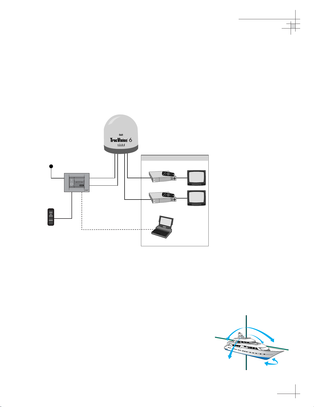
1.1 TracVision 6 System Overview
A complete satellite TV system includes the TracVision 6 antenna
connected to the switchplate, an IRD (satellite TV receiver), and a
television set. The optional TV/SAT Switch allows you to select a
satellite at the press of a button. A desktop or laptop computer is
used to configure the system and conduct diagnostics. The
complete system is illustrated in Figure 1-1. System specifications
are provided in Appendix A on page 71.
System Compatibility
The TracVision 6 satellite antenna is fully compatible with Digital
Video Broadcasting (DVB
®
) satellites, as well as DIRECTV®‘s
Digital Satellite Service (DSS) satellites. The system is also fully
compatible with KVH’s TracNet
™
2.0 Mobile High-speed Internet
System (for more information about TracNet 2.0, please visit our
web site at www.kvh.com).
In-motion Tracking
The TracVision 6 uses a state-of-the-art actively stabilized antenna
system. Once the satellite is acquired, the antenna gyro
continuously measures the heading, pitch, and roll of your vessel
and sends commands to the antenna motors to keep the antenna
pointed at the satellite at all times.
Figure 1-1
TracVision 6 System Diagram
Figure 1-2
TracVision Identifies and
Compensates for Vessel Motion
TracVision 6 Antenna
11-16 VDC
3.5 - 4.5 Amps
Switchplate
Powe r
RF
Options Purchased Separately
Satellite Receiver 1
TV 1
Data
TV/SAT Switch
RF
(optional)
E
r
r
o
r
S
a
t
A
S
a
t
B
S
e
le
c
t
C
h
a
n
g
i
n
g
S
a
e
t
l
l
i
t
e
s
:
1
.
P
u
s
h
S
e
l
e
c
t
b
u
t
t
o
n
2
.
W
a
i
t
w
h
i
l
e
S
a
t
A
o
r
B
b
l
i
n
k
s
g
r
e
e
n
3
.
R
e
a
d
y
w
h
e
n
S
a
t
A
o
r
S
a
t
B
s
t
a
y
s
s
o
l
i
d
g
r
e
e
n
O
t
h
e
r
I
n
d
i
c
a
t
o
r
s
:
•B
o
t
h
b
l
i
n
k
i
n
g
g
r
e
e
n
:
i
n
i
t
i
a
l
i
z
i
n
g
•E
r
r
o
r
l
i
g
h
t
b
l
i
n
k
i
n
g
r
e
d
:
s
y
s
t
e
m
p
r
o
b
l
e
m
Satellite Receiver 2
TV 2
PC Maintenance
Laptop PC
TracVision
Page 9
54-0166
4
TracVision 6 Technical Manual
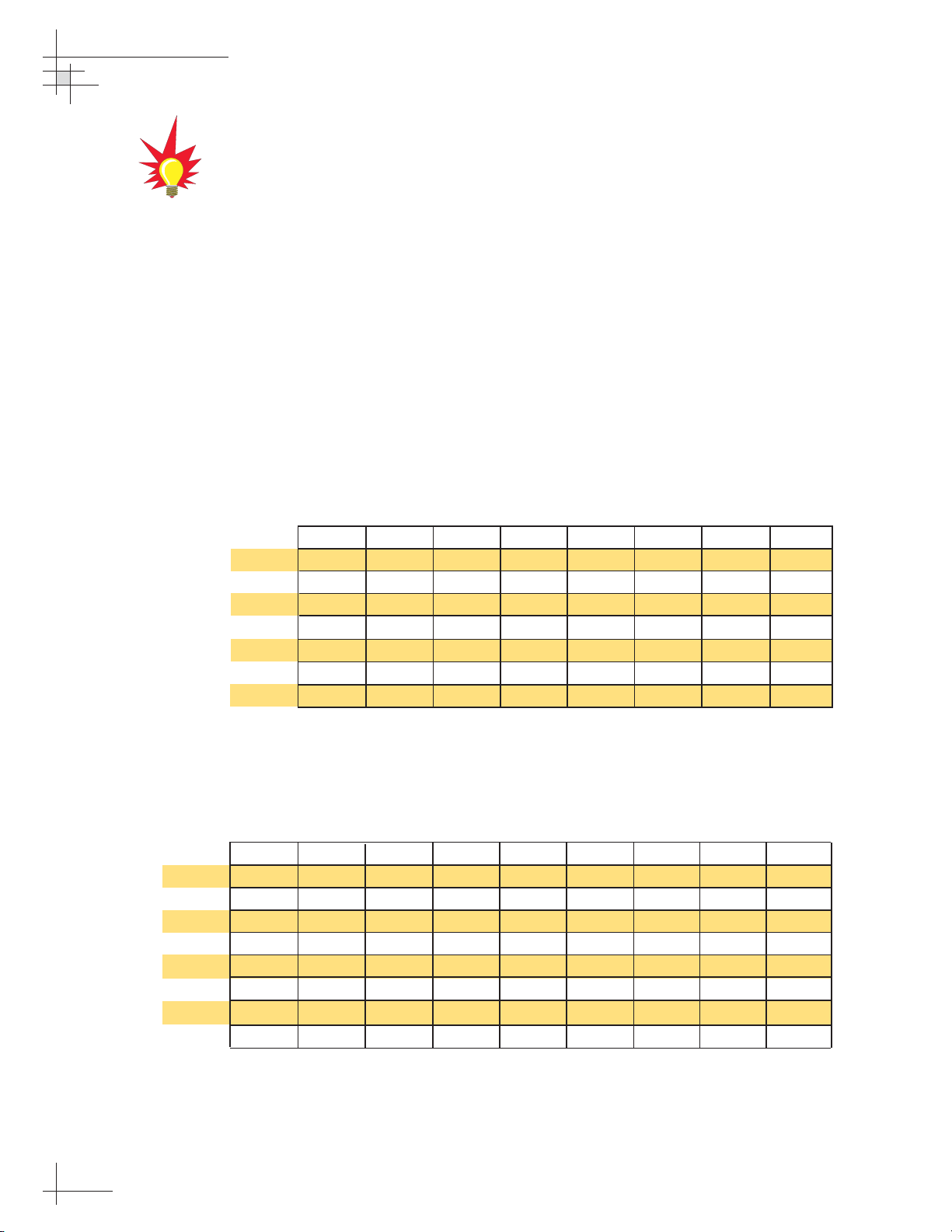
Satellite Library
Your TracVision 6 includes a pre-programmed satellite library of
North American, European, and Latin American satellite
services. When configuring the TracVision 6, you may choose a
pair of satellites from the library to be active in the system and
with your IRD.
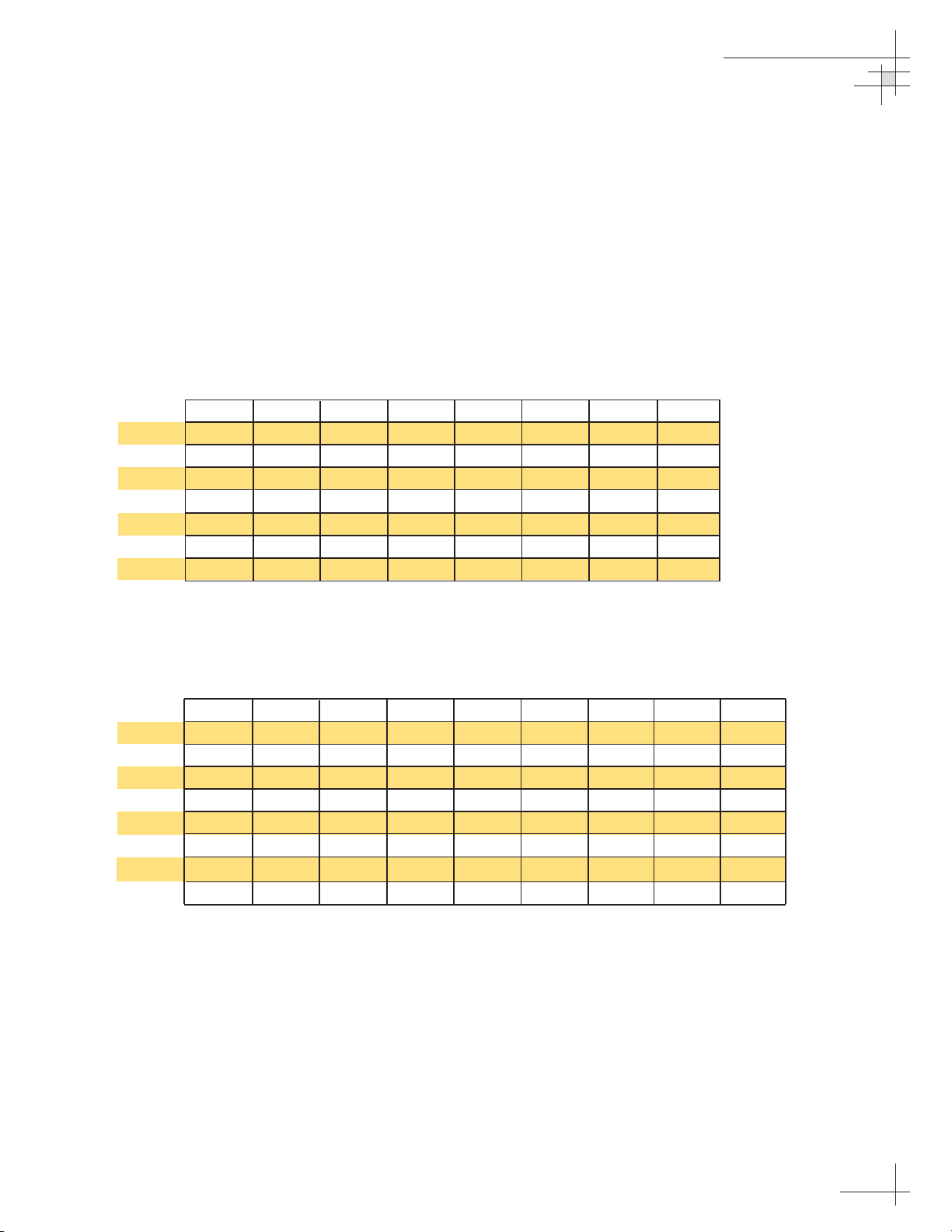
For the antenna to track and receive signals from two satellites,
they must be within 10º longitude of each other in orbit. As a
result, certain satellites can be paired only with certain other
satellites. Tables 1-1 and 1-2 list the possible satellite pairs that
may be selected in North America and Europe. In Latin America,
the system can track Galaxy3CN, Galaxy3CS, or PAS_9 (Latin
American LNB required). If the satellite service you wish to receive is
not listed in the satellite library, you may add two additional satellites
of your choice to the library.
TracVision 6’s default satellite pairs
are:
N. America (US DIRECTV):
DSS_101 & DSS_119
Europe: ASTRA1 & HOTBIRD
L. America (DIRECTV LA):
GALAXY3CN & NONE
Table 1-2
Available Satellite Pairs - Europe
(European LNB required)
Table 1-1
Available Satellite Pairs
- North America
(North American LNB required)
DSS_101 ✓✓✓
DSS_119 ✓✓✓
Echo_61 ✓✓ ✓✓
Echo_110 ✓ ✓✓✓✓
Echo_119 ✓✓ ✓✓✓
Echo_148 ✓✓ ✓✓
Expressvu ✓✓✓✓✓✓ ✓
ExpressTV ✓✓✓✓✓✓✓
Astra 1 Astra 2N Astra 2S Hispasat Hotbird WB Sirius Thor Arabsat Nilesat
Astra 1 ✓✓ ✓✓ ✓
Astra 2N ✓✓✓
Astra 2S ✓✓✓
Hispasat
Hotbird WB ✓✓ ✓ ✓
Sirius ✓✓✓
Thor ✓✓
Arabsat ✓✓ ✓ ✓
Nilesat ✓✓
DSS_101 DSS_119 Echo_61 Echo_110 Echo_119 Echo_148 Expressvu ExpressTV
Page 10
1.2 TracVision 6 Components
Your TracVision 6 system includes the following components:
Antenna Unit
The antenna unit houses the antenna positioning mechanism, low
noise block (LNB), power supply, and control elements within a
molded ABS radome. Weathertight connectors on the bottom of
the baseplate join the power, signal, and control cabling from
belowdecks units.
Switchplate
The switchplate controls power to the antenna via the On/Off
switch. It also provides a DB9 maintenance port for connecting a
computer or TV/SAT Switch for changing satellites and
configuring the system.
Integrated Receiver Decoder (IRD)
(Satellite TV Receiver)
The IRD (purchased separately) receives satellite signals from the
antenna unit for signal processing and channel selection, and
sends the signals to the TV set for viewing. Please refer to the
user’s manual provided with your selected IRD for complete
operating instructions.
Introduction
54-0166
5
Before you can start watching
satellite TV using your TracVision
antenna, you will need to activate
your IRD. Refer to
Section 2.6,
“Activating/Programming the IRD”
on page 27
for details.
Page 11
1.3 Materials Provided With the
TracVision 6
Table 1-3 lists the components and materials in the TracVision 6
shipping carton.
Component KVH Part No.
Antenna Unit 02-1045-01HP
†
02-1045-02HP
††
02-1045-03HP
†††
02-1045-04HP
††††
Switchplate 02-1023
Installation Kitpack 72-0103
Data Cable 32-0619-100
PC Cable 32-0628-06
RF Cable* 32-0566-100
Power Cable 32-0510-100
Ground Cable 32-0583-50
TracVision 6 Technical Manual
54-0166
TracVision 6 User’s Guide
54-0166-01
†
North American system
††
European system with dual-output LNB
†††
Latin American system
††††
European system with quad-output LNB
* Not supplied with European quad-output LNB systems
54-0166
6
TracVision 6 Technical Manual
Table 1-3
TracVision 6 Packing List
For a list of items supplied in the
kitpack, see Table 2-3 on page 10.
Page 12

Installation
54-0166
7
2 – Installation
This section explains how to install, configure, and test the
TracVision 6 system. Follow the simple procedures in this section
sequentially to ensure a safe and effective installation.
Contents
2.1 Planning the Installation . . . . . . . . . . . . . . . . . . . . . . . . . . . . . . . . . . . .9
2.2 Mounting the TracVision Antenna . . . . . . . . . . . . . . . . . . . . . . . . . . . .15
2.3 Connecting the IRD(s) . . . . . . . . . . . . . . . . . . . . . . . . . . . . . . . . . . . .19
2.4 Wiring the Switchplate . . . . . . . . . . . . . . . . . . . . . . . . . . . . . . . . . . . .23
2.5 Mounting the Switchplate . . . . . . . . . . . . . . . . . . . . . . . . . . . . . . . . . .26
2.6 Activating/Programming the IRD . . . . . . . . . . . . . . . . . . . . . . . . . . . .27
2.7 Installing Satellites to Track . . . . . . . . . . . . . . . . . . . . . . . . . . . . . . . .29
2.8 Setting the Skew Angle
(European Systems Only) . . . . . . . . . . . . . . . . . . . . . . . . . . . . . . . . . .37
2.9 Checking Out the System . . . . . . . . . . . . . . . . . . . . . . . . . . . . . . . . . .38
2.10 Changing Geographic Location . . . . . . . . . . . . . . . . . . . . . . . . . . . . . .40
Page 13
Installation
54-0166
9
2.1 Planning the Installation
Who Should Install the TracVision 6
KVH recommends that a KVH-authorized technician install the
TracVision 6 system. Installers should have experience installing
electronic equipment on a vessel.
Materials and Equipment Required for Installation
Before you begin installing the TracVision 6 system, you need to
verify that you have all of the following tools and materials:
• Electric drill
•
1
⁄2" (13 mm) drill bit and 3" (80 mm) hole saw
• Socket wrenches and
7
⁄16" open end wrench
• Flat head and Phillips screwdrivers
• Crimp tool (Augat T1000 or equivalent)
• Light hammer; center punch; tape; scriber/pencil
• Terminal lug crimping tool; wire strippers
• RG-6 or RG-11 cable with F-type connectors for
extra RF cables as needed. Refer to Table 2-1 to
determine the number of RF cables that you will need.
Connecting to: # RF Cables
North American/Latin American Systems
One IRD 1
Two IRDs 2
Three or more IRDs 2*
European Systems with Dual-output LNB
One IRD 1
Two IRDs 2
European Systems with Quad-output LNB
One IRD 1
Two IRDs 2
Three IRDs 3
Four IRDs 4
More than four IRDs 4*
* Multiswitch needed. Follow multiswitch manufacturer’s guidelines.
Plan the entire installation before
proceeding! Take into account
antenna unit placement, cable
running distances between units,
and accessibility to the equipment
after installation.
Table 2-1
Number of RF Cables to Connect
to the Antenna
RG-11 or RG-6 cable with F-type
connectors is required for all RF
wiring. Use of any other cable will
result in degraded performance.
Use RG-6 cable for distances up to
75 ft (23 m); use RG-11 cable for
distances greater than 75 ft (23 m).
The KVH warranty does not cover
degraded performance due to
improper wiring.
You may want to connect four RF
cables to the antenna in all cases.
That way, if an IRD is added in the
future, no additional RF cables will
need to be run.
Page 14
• A PC with terminal emulation software such as
Windows Hyperterminal or PROCOMM.
• Power cable to connect the switchplate to ship’s
power (Table 2-2 provides proper gauge and
length specifications).
Cable Length Cable Gauge
to 50 ft (15 m) 14 AWG (1.5 mm2)
+50 ft (+15 m) 12 AWG (2.5 mm2)
Kitpack Contents
The kitpack packaged with your antenna unit contains various
hardware and other materials that will be needed to complete the
TracVision system installation. Ensure that the kitpack contains
all of the items listed in Table 2-3.
Part Qty. KVH Part No.
3
⁄8"-16 x 3" hex head screws 4 14-0227-48
3
⁄8" flat washers 8 14-0229
3
⁄8"-16 hex nuts 4 14-0228
3
⁄8" lock washers 4 14-0230
3
⁄8" fiber shoulder washers 8 14-0336
Plastic screw covers 12 19-0088
Foam seal 1 24-0142
Tie-wraps 2 22-0013
Core clamp (ferrite) 1 29-0037-02
54-0166
10
TracVision 6 Technical Manual
Table 2-3
Kitpack Contents
Table 2-2
Recommended Switchplate-to-
Ship’s Power Cable Specifications
Page 15

Choosing Component Locations
The major considerations in locating the TracVision components
are described below.
Cable Lengths
When determining component locations, keep in mind
accessibility and cable lengths between units. Lengths of these
cables are as follows:
Cable (Function) Length
Data Cable (Switchplate to Antenna Unit) 100 ft (30 m)
PC Cable (Switchplate to PC) 6 ft (2 m)
RF Cable (Antenna to IRD)* 100 ft (30 m)
Power Cable (Switchplate to Antenna Unit) 100 ft (30 m)
IRD Ground Cable (IRD to Switchplate) 50 ft (15 m)
* Not included with European quad-output LNB systems
Installation
54-0166
11
Table 2-4
Lengths of Provided
Belowdecks Cables
Page 16
Choosing the Best Location for the TracVision Antenna
There are several factors to consider when choosing the location
for the TracVision antenna.
• Since the TracVision antenna requires a clear view
of the southern sky to receive satellite signals, the
ideal antenna site has an unobstructed view of the
horizon/satellite all around. The less blockage, the
better the system performs.
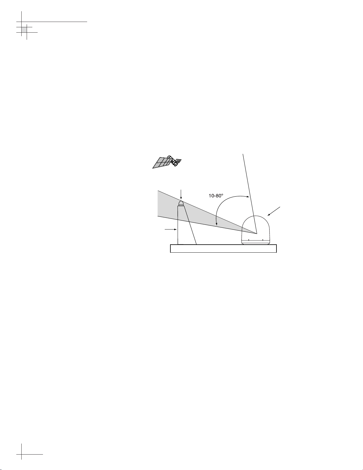
• Keep the antenna clear of any obstructions above
decks. The antenna requires a 10º to 80º look angle
to receive satellite signals.
• To minimize tracking errors, place the antenna
unit as close as possible to the intersection of the
vessel’s fore-and-aft centerline and midships.
• The mounting surface should be flat and strong
enough to carry the complete assembly (55 lbs/
25 kg). To prevent warpage to the antenna
baseplate, make sure that the mounting surface is
rigid so that it cannot flex when the vessel
vibrates. If necessary, add a strength member to
the mounting site to stiffen it.
• Be sure to account for the height and base
dimensions (see Figure 2-2 on the following page).
54-0166
12
TracVision 6 Technical Manual
Figure 2-1
Antenna Blockage
Blocked!
TracVision Antenna
Mast
Vessel Platform
Page 17
Radar Concerns
The TracVision antenna must be kept out of line with nearby
radars, as their energy levels may overload the antenna’s frontend circuits. In an ideal installation, the antenna is mounted four
feet (1.2 m) above and four feet (1.2 m) away from the radar
(measured from the center of the antenna dome to the center of
the radar).
The best placement for the TracVision antenna is above the radar.
However, if there will be a significant horizontal separation
between the radar and TV dome (i.e., at least 8 to 10 feet (2.5 to
3 m)), the TracVision antenna can be placed below the radar as
there will be little chance of signal blockage.
Installation
54-0166
13
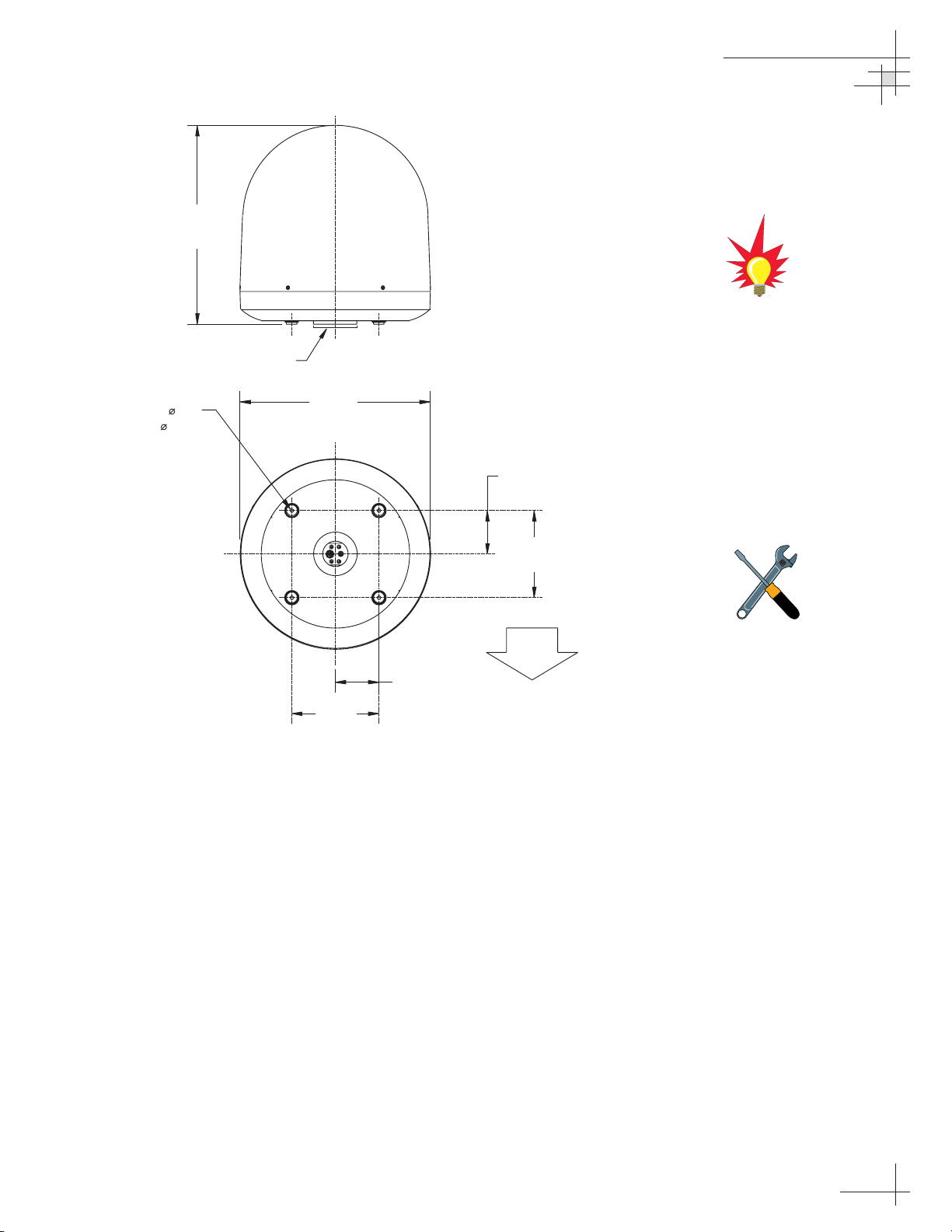
Figure 2-2
Antenna Unit Dimensions
The radome exterior is treated
with a special finish selected for
compatibility with the dome material
and transparency to the satellite
signals. Application of additional
paints or finishes WILL degrade
performance, potentially beyond
acceptable limits.
A full-size template of the baseplate
mounting holes has been provided
at the back of this manual.
27.36"
(695 mm)
Compression Seal
4x .50"
(4x 13 mm)
26.2"
(665 mm)
6.0" (152 mm)
12.0"
(305 mm)
FWD
6.0" (152 mm)
12.0"
(305 mm)
Page 18
Locating the Switchplate
A switchplate has been provided to serve as the hub of the
TracVision 6 wiring (with the exception of the RF cable, which
will be connected to the IRD). The switchplate includes an
On/Off switch and a DB9 maintenance port for easy access to the
antenna unit’s software and diagnostics. Follow the steps below
to select and prepare the switchplate mounting location.
1. Select a location to mount the TracVision 6
switchplate. It should be installed in a dry, flat
location within reach of the cables that will
connect to the antenna unit and allowing easy
access to the front panel.
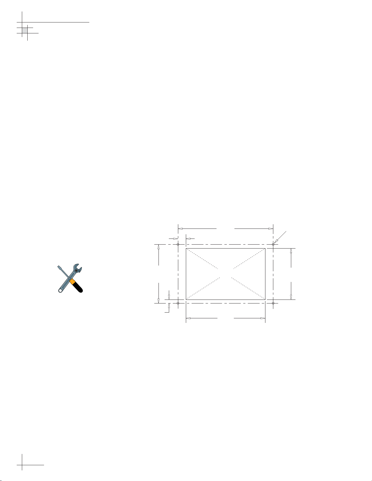
2. Once you’ve decided on a suitable location, create
a panel cutout in the mounting surface.
Figure 2-3 illustrates the mounting dimensions
and a template has been provided in Appendix B.
The connecting cables will be routed through this
cutout.
54-0166
14
TracVision 6 Technical Manual
Figure 2-3
Switchplate Panel
Cutout Dimensions
A full-scale panel cutout template
has been provided in
Appendix B
on page 73.
2.36"
(60 mm)
.16" (4 mm)
3.82"
(97 mm)
.32" (8 mm)
Panel Cutout
3.19"
(81 mm)
3
/32" (2.5 mm) dia
2.05"
(52 mm)
Page 19
2.2 Mounting the TracVision
Antenna
1. Make sure that you have chosen a suitable
mounting location based upon the guidelines in
“Choosing the Best Location for the TracVision
Antenna” on page 12.
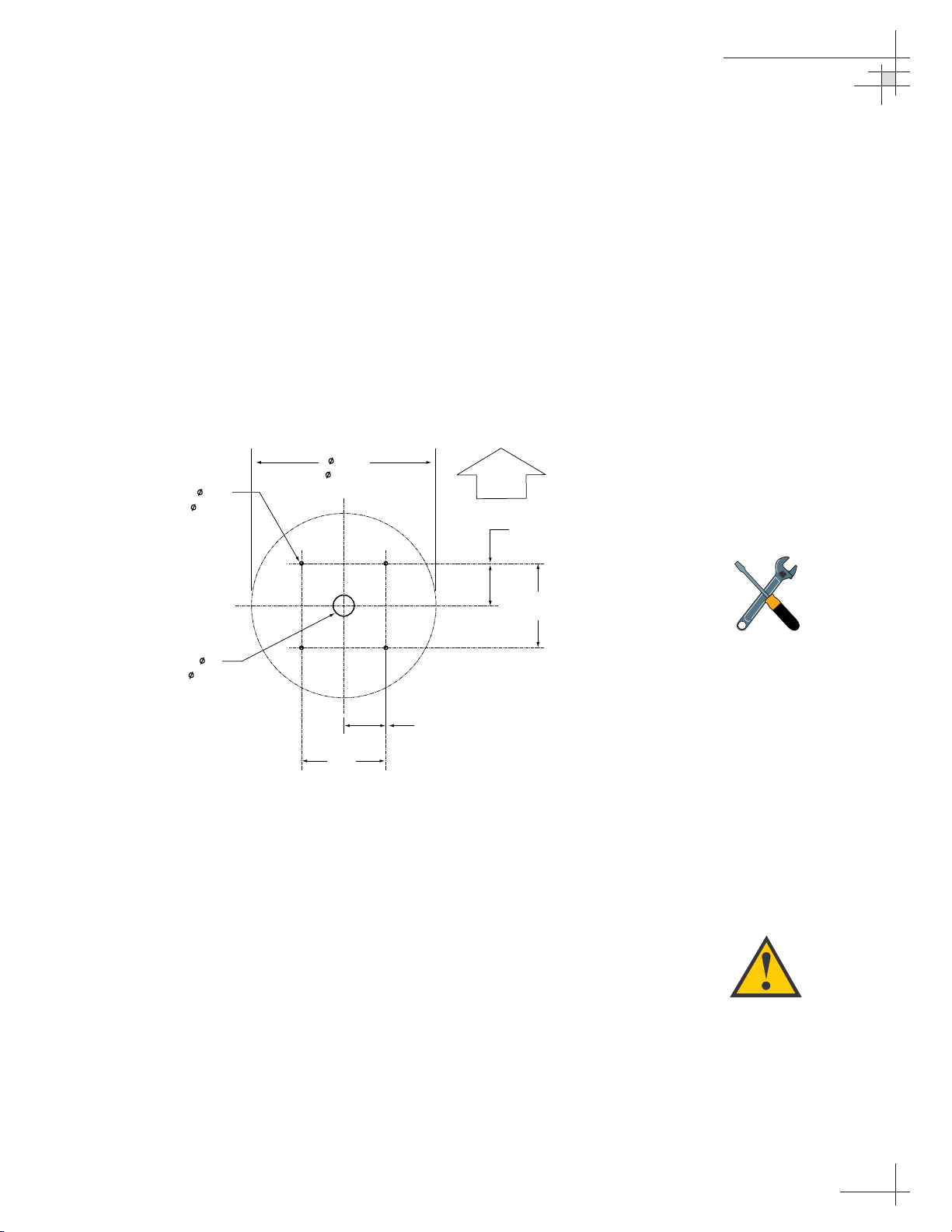
2. Using the template provided at the back of this
manual or the dimensions shown in Figure 2-4, lay
out the four mounting bolt holes and cable access
hole at the mounting site. Make certain that the
“FWD” arrow is parallel with the vessel’s
centerline and pointed toward the bow.
3. Drill the four
1
⁄2" (13 mm) bolt holes and cut out the
3" (80 mm) diameter cable access hole (following
the layout in Step 2). Smooth the edges of the cable
access hole to protect the cables.
4. Bring the data cable, power cable, and RF cable(s)
from belowdecks up through the cable access hole
in the mounting surface (see Table 2-1 on page 9 to
determine the number of RF cables required).
Belowdecks, route the opposite end(s) of the RF
cable(s) to the IRD(s) or multiswitch; route the
opposite ends of the data cable and power cable
through the switchplate panel cutout.
Installation
54-0166
15
Figure 2-4
Antenna Mounting Holes Layout
Be careful not to strike the exposed
connectors extending from the
bottom of the baseplate or allow
them to carry the weight of the
antenna unit.
A full-size template of the baseplate
mounting holes has been provided
at the back of this manual.
DOME
26.2"
4 x 0.5"
(4 x 1.3 cm)
3"
( 7.6 cm)
( 67 cm)
6"
(15.2 cm)
12"
(30.5 cm)
F
D
W
(15.2 cm)
(30.5 cm)
6"
12"
Page 20
5. Remove the antenna unit from its shipping carton
and set the radome aside in a safe place. If you
bring the radome topside, be sure to secure it with
a lanyard so that it does not fall overboard.
6. Remove the foam shipping restraints from the
antenna unit.
7. Place the foam seal in position on the mounting
surface with the hole centered over the cable
access cutout. Do not remove the paper backing at
this time. Scribe a line all around the seal.
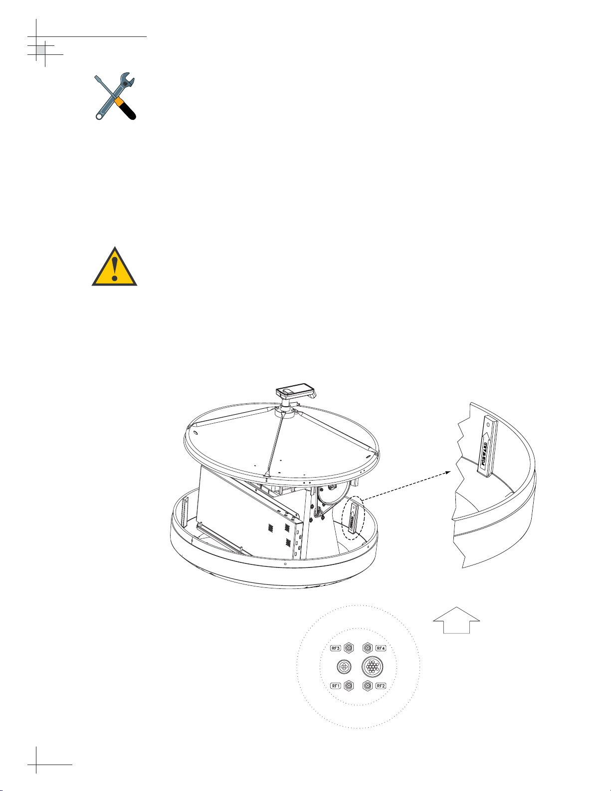
8. Position the baseplate assembly in place over the
mounting holes and cable access, with the
baseplate’s “Forward” arrow (shown in Figure 2-5)
pointing toward the bow. Ensure that all holes line
up and that the connectors are centered over the
cable access as shown in Figure 2-6. Make any
necessary adjustments before seating the foam seal
in place permanently.
54-0166
16
TracVision 6 Technical Manual
Figure 2-5
Baseplate “Forward” Arrow
Figure 2-6
Baseplate/Foam Seal Orientation
(Bottom View)
The foam shipping restraints must
be removed before power is
applied. Save the restraints for
reuse and be sure to install them
whenever the antenna unit is
moved from place to place. See
Section 4.9, “Preparing for
Shipment” on page 67
for details.
For the antenna to work properly,
the baseplate’s “Forward” arrow
MUST be parallel with the vessel’s
centerline and pointed toward the
bow.
FWD
Page 21
9. Clean the mounting surface where the foam seal
will be placed. Remove the paper backing from the
foam seal to expose the contact cement, then lay
the foam seal in place, adhesive side down, and
press down firmly to bring the adhesive into full
contact along the mounting surface.
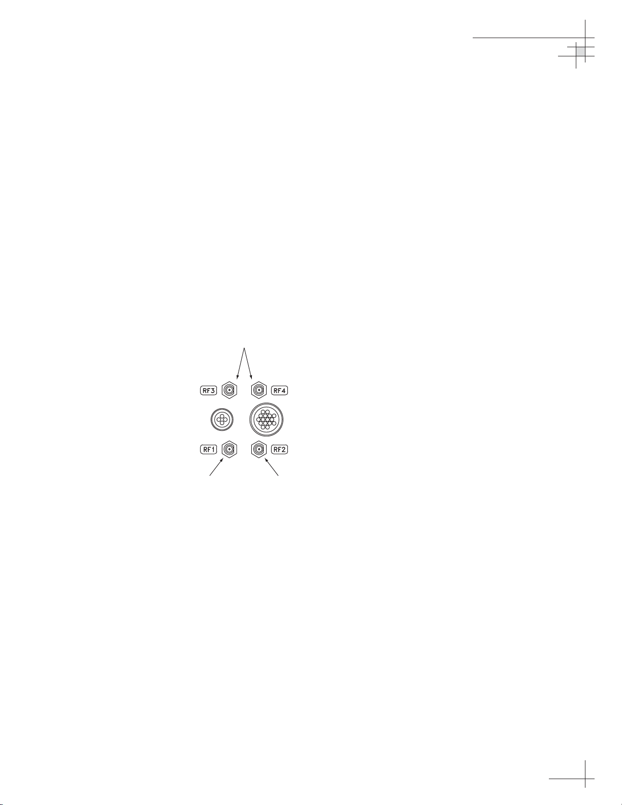
10. Connect the data, power, and RF cables from
belowdecks to the baseplate as shown in
Figure 2-7. Turn the power and data cable
connectors down until locked in place; don’t use
excessive force. Connect the RF cable(s) with a
7
⁄16"
wrench, applying 30 pounds of torque. If you
connect more than one RF cable, label both ends of
each RF cable to match its antenna baseplate
connector (RF1, RF2, RF3, or RF4). Do NOT use
teflon gel on the cable fittings as it reduces
signal strength at higher frequencies.
11. Place the antenna baseplate over the holes drilled
in the foundation, ensuring the “Forward” label
(shown in Figure 2-5) points toward the bow.
Installation
54-0166
17
Figure 2-7
Baseplate Connector Assignments
(Bottom View)
Used only with
Quad-output LNB
DataPower
Single IRD
Installation
Second IRD
Installation
Page 22
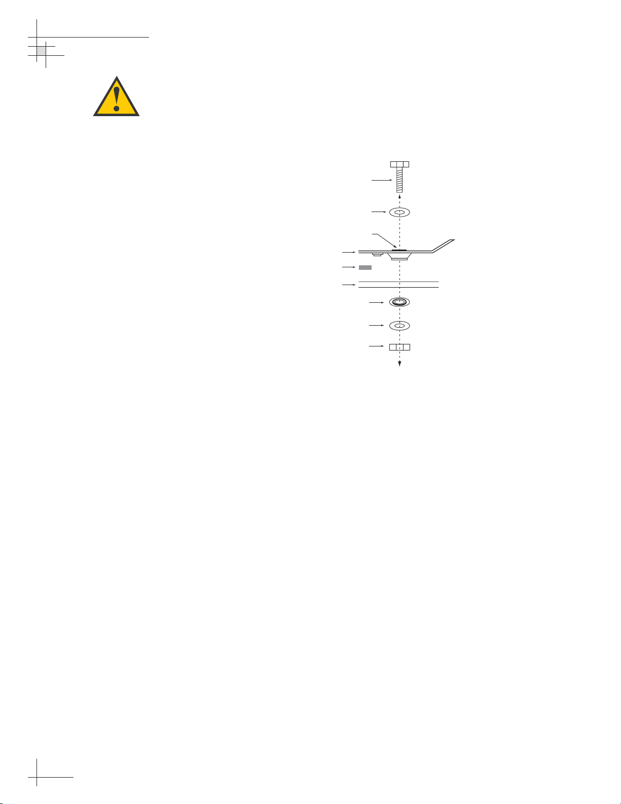
12. At each of the four baseplate mounting holes,
place a
3
⁄8" flat washer on a 3⁄8"-16 bolt and insert the
bolt into the hole from above, as shown in
Figure 2-8. Carefully rotate the azimuth
mechanism plate to expose all four mounting
holes.
13. Apply a
3
⁄8" fiber shoulder washer, 3⁄8" flat washer,
and
3
⁄8"-16 lock nut from below, as shown in
Figure 2-8.
14. Tighten securely (but do not overtighten) until the
foam seal is compressed as far as it will go and all
four feet are bottomed against the mounting
surface.
15. If you are installing a European system:
Leave the radome off for now; you will install it
later.
If you are installing a North American or Latin
American system:
Place the radome over the baseplate. Align the six
radome screw holes with the inserts in the
baseplate, insert the #10-32 screws and tighten.
Install a protective plastic screw cap from the
kitpack over each screw.
54-0166
18
TracVision 6 Technical Manual
Figure 2-8
Bolting the Antenna Unit to
the Deck (Side View)
When rotating the azimuth
mechanism by hand, go slowly.
Hitting the mechanical stops with
excessive force will damage the
azimuth limit switch.
Bolt
Flat Washer
Shoulder Washer
(Preinstalled)
Antenna Unit Base
Foam Seal
Deck
Shoulder Washer
Flat Washer
Lock Nut
Page 23
Installation
54-0166
19
2.3 Connecting the IRD(s)
For the TracVision system to work, you must connect the
following cables to your satellite TV receiver(s) (IRDs):
• RF Cable
• Ground Wire
Connecting the RF Cable(s)
Each RF cable must be an RG-11 (75 ohms) or RG-6 (75 ohms)
cable fitted with F-type connectors. The RF cable(s) should
already be connected to the antenna baseplate (see Step 10 of
Section 2.2., “Mounting the TracVision Antenna” on page 17). The
following sections explain how to connect the RF cable(s) to your
IRD(s).
To connect the TracVision antenna to your IRD(s), choose one of
the following configurations (based on the number of IRDs you
will connect to the antenna):
Option 1 - Connecting One IRD
Option 2 - Connecting Two IRDs
Option 3 - Connecting Three or More IRDs
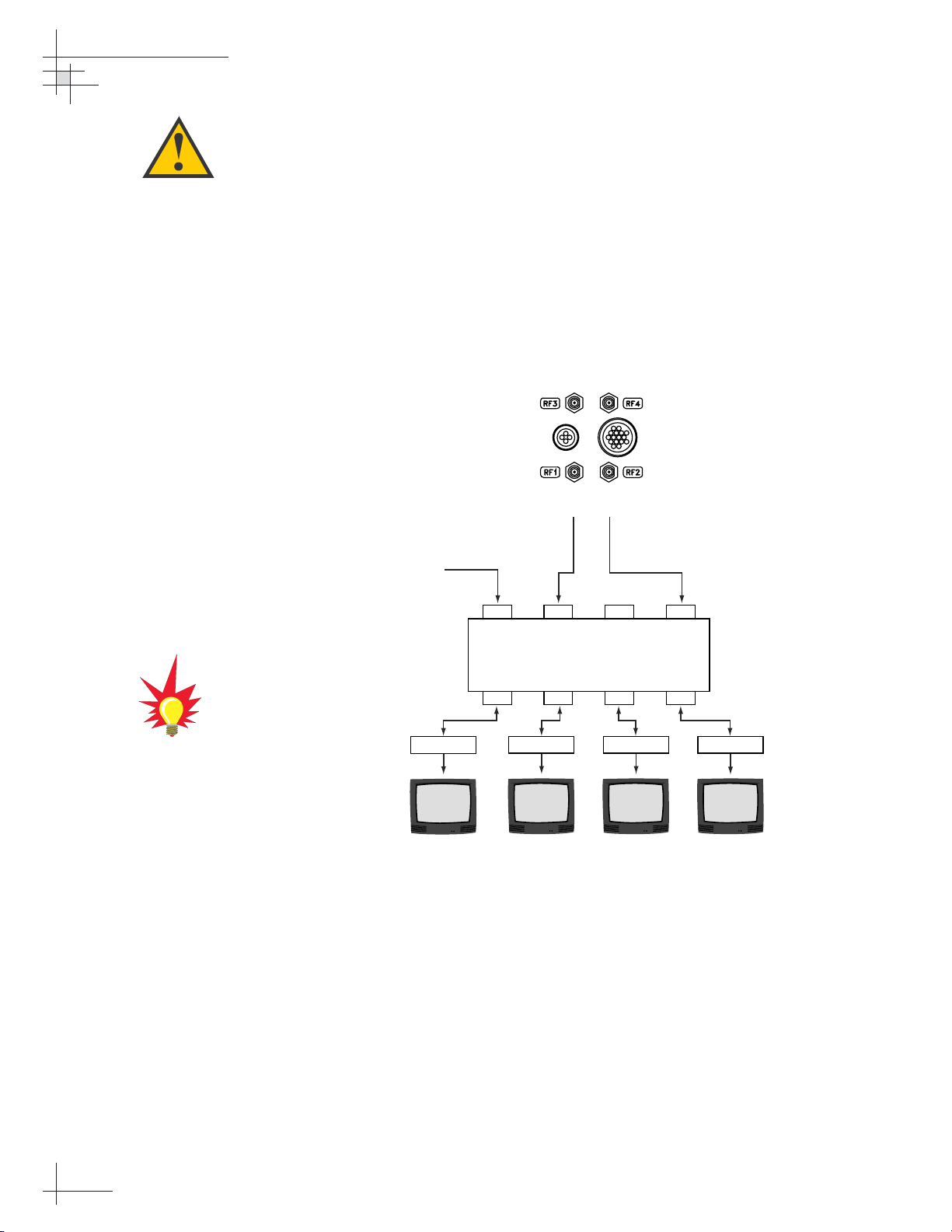
Option 1 - Connecting One IRD
One end of the RF cable should already be connected to the
connector labeled “RF1” on the base of the TracVision antenna.
Connect the other end of the RF1 cable to the IRD connector
labeled “LNB,” “ANT/SAT,” or “SATELLITE IN.”
Option 2 - Connecting Two IRDs
Two RF cables should already be connected to the connectors
labeled “RF1” and “RF2” on the base of the TracVision antenna.
Connect the other ends of these RF cables to the connector
labeled “LNB,” “ANT/SAT,” or “SATELLITE IN” on the two
IRDs.
The IRD that is connected to the RF1 cable controls which
satellite the antenna is tracking. The IRD connected to RF2 can
select different channels on that satellite but not change the
satellite selection itself.
For instructions on RF wiring for
TracNet, please refer to the
Tr ac Ne t
Owner’s Manual
or
Technical
Manual
.
Before you connect an RF cable to
an IRD, turn on the IRD and TV
and verify that there is no AC
voltage present on the IRD’s input
connector, measured between
center conductor and shield. If AC
voltage is present on the connector,
DO NOT
connect the RF cable until
you have corrected the problem.
This is a potentially dangerous
condition that will damage the
antenna’s electronics.
Page 24
Option 3 - Connecting Three or More IRDs
(North American and Latin American Systems)
To connect three or four IRDs to the TracVision antenna, you will
need to install an active multiswitch (Channel Master model
6214IFD or equivalent) between the antenna and the IRDs. Two
RF cables should already be connected to the connectors labeled
“RF1” and “RF2” on the base of the TracVision antenna.
Figure 2-9 shows a typical wiring arrangement for three or four
IRDs. Mount the multiswitch unit in accordance with the
manufacturer’s instruction sheet.
1. Connect the RF cable labeled "RF1" to the
multiswitch input labeled "LNB RHCP +13V.”
2. Connect the RF cable labeled “RF2” to the
multiswitch input labeled "LNB LHCP +18V.”
3. Connect the multiswitch outputs to individual IRD
inputs. Use RG-6 cable with F-type connectors for
all RF connections. Terminate all unused output
connectors with 75 ohm DC blocks (Channel
Master #7184, Radio Shack #15-1259 or equivalent).
54-0166
20
TracVision 6 Technical Manual
Figure 2-9
Single Multiswitch Installation
(North American and Latin
American systems only)
The use of an active multiswitch will
interfere with the 22 KHz tone sent
by DIRECTV DSS Plus™IRDs to
the antenna. As a result, the
antenna will not receive the signal
to change satellites when you
change channels using your
DIRECTV DSS Plus remote. You
will need to use the optional
TV/SAT Switch* or a PC to switch
between satellites.
* To order a TV/SAT Switch (KVH Part
Number 01-0245), please call
+1 401 847-3327.
Due to the signal polarization in
European satellites, the use of a
multiswitch with a dual-output LNB
will result in a loss of signal and
less than optimal operation with
TracVision 6 systems used in
Europe.
TracVision Antenna Baseplate
RF1 RF2
DC Power
DC In RHCP
Out 1 Out 2 Out 3 Out 4
+13v
VHF/UHF LHCP
Multiswitch
+18v
IRD #1
IRD #2 IRD #3
IRD #4
Page 25
Installation
54-0166
21
Multiple Multiswitch Installation
If you need to connect more than four IRDs to the TracVision
antenna, you may carry out a multiple multiswitch installation,
as shown in Figure 2-10.
Figure 2-10
Multiple Multiswitch Installation
(North American and Latin
American systems only)
DC Power
DC In RHCP
IRD #1
+13v
Out 1 Out 2 Out 3 Out 4
IRD #2 IRD #3
VHF/UHF LHCP
Multiswitch
TracVision Antenna Baseplate
RF1 RF2
RF Splitters/
Power Dividers
+18v
DC Power
IRD #4
DC In RHCP
Out 1 Out 2 Out 3 Out 4
+13v
Multiswitch
VHF/UHF LHCP
+18v
IRD #5 IRD #6 IRD #8IRD #7
Page 26
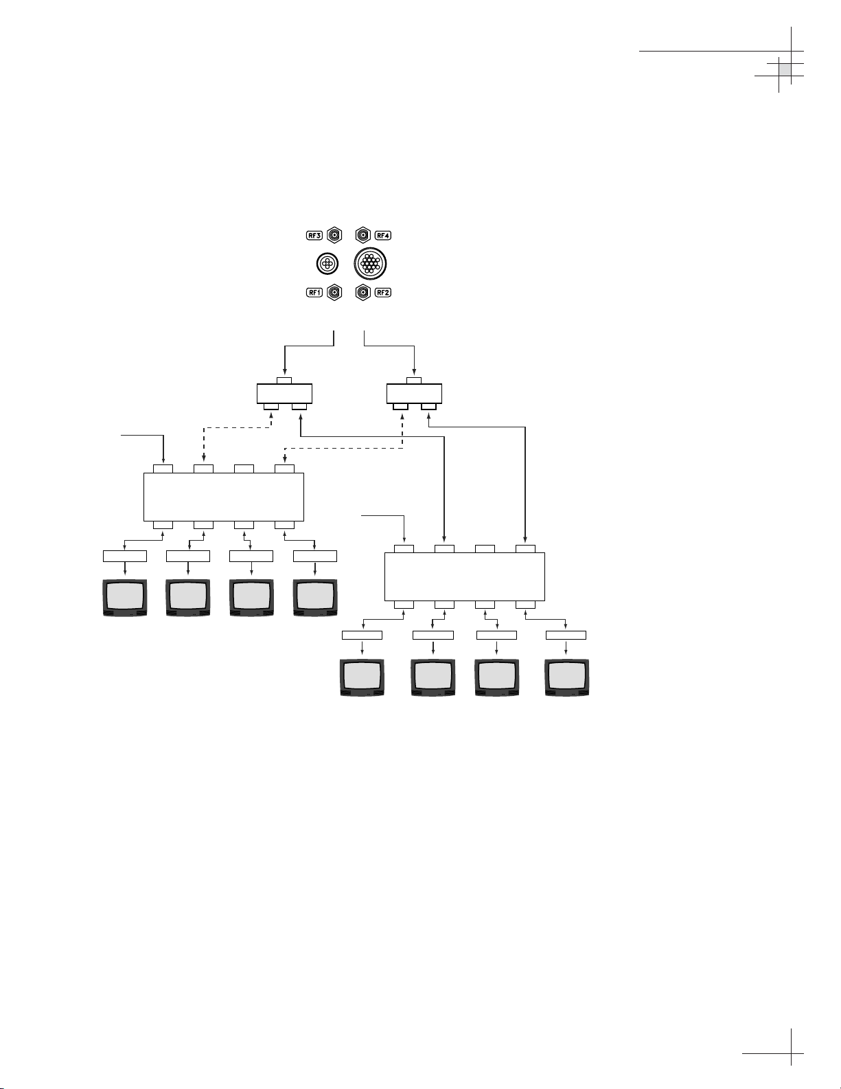
Option 3 - Connecting Three or More IRDs
(European Quad-output LNB Systems)
In European systems that come with a quad-output LNB, all four
RF outputs from the TracVision antenna can be connected to
individual IRDs.
Connecting Three or Four IRDs
To connect a third IRD, a third RF cable should already be
connected to the plug labeled “RF3” on the base of the TracVision
antenna. Connect the other end of the RF3 cable to the plug
labeled “LNB,” “ANT/SAT,” or “SATELLITE IN” on the third
IRD. To connect a fourth IRD, use the fourth RF cable, which
should already be connected to the plug labeled “RF4” on the
base of the antenna.
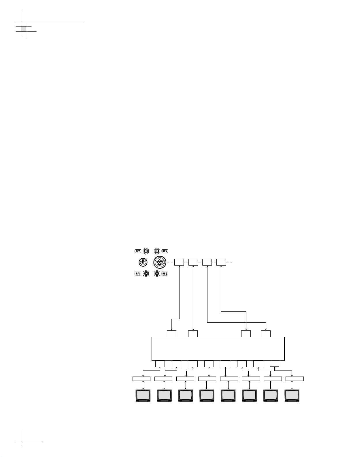
Connecting More than Four IRDs
To connect more than four IRDs, you will need to install an active
multiswitch between the antenna and the IRDs. Connect the
multiswitch unit in accordance with the manufacturer’s
instructions. Figure 2-11 shows an example of a European
multiswitch configuration.
54-0166
22
TracVision 6 Technical Manual
Figure 2-11
Multiswitch Installation
(European Quad-output LNB
systems only)
TracVision Antenna Baseplate
RF4
RF3 RF2 RF1
RF4 RF3 RF2 RF1
RF cables
supplied by customer
Ver t. H or.
Active Multiswitch
Out 1 Out 2 Out 3 Out 4 Out 5 Out 6 Out 7 Out 8
Vert./mod.
5-50 kHz
Hor./mod.
IRD #2IRD #1 IRD #3 IRD #6 IRD #7 IRD #8IRD #4 IRD #5
Page 27
Connecting the IRD Ground Wire
A grounding wire has been provided to connect your IRD to a
suitable ground. Attach the grounding wire to any suitable screw
on the rear panel of the IRD with a good contact with the IRD
chassis. The other end should be connected to a suitable DC
ground, ideally to the switchplate’s ground terminal (route the
ground wire through the switchplate panel cutout and leave
unconnected for now). Each IRD that you connect to the
TracVision system should have a similar ground connection.
If you are using a multiswitch, you can ground the multiswitch instead
of the individual IRDs.
2.4 Wiring the Switchplate
All other wiring for the TracVision system connects to the
switchplate. For the TracVision system to work, you must wire
the following cables to the switchplate:
• Antenna Data Cable
• Antenna Power Cable
• Vessel Power Cable
• IRD Ground Wire(s)
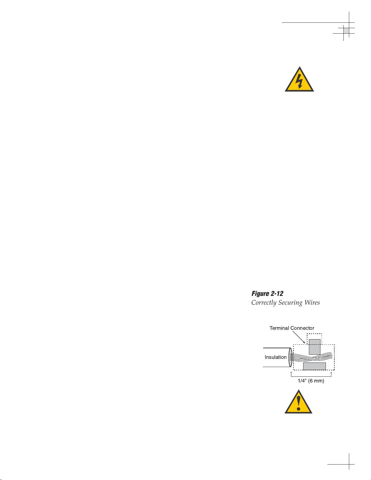
Tips for Safe and Successful Wiring
• When attaching cables to the TracVision 6
switchplate connectors, make sure the insulation is
stripped back approximately
1
⁄4" (6 mm). Twist the
wires gently to help achieve a good connection. Do
not pinch insulation inside the connector.
• After attaching the power and data cables to the
appropriate terminal connector strips, tug gently
to ensure a firm connection.
• Do not tin (solder) the wire ends.
• All cables should be routed and dressed before
terminating at the switchplate. The antenna data
and power cables may be trimmed to desired
length. However, be sure to cut back the data
cable’s drain wire (shield); do NOT connect the
drain wire to anything.
Installation
54-0166
23
Be sure to connect a ground cable
from each IRD to a suitable DC
ground, ideally the switchplate’s
ground terminal.
Figure 2-12
Correctly Securing Wires within
the Switchplate Connectors
Do
NOT
connect the antenna data
cable’s drain wire (shield).
Page 28

Connecting the Antenna Data Cable
Find the TracVision 6 data cable where it comes through the
panel cutout made earlier. Wire the data cable to the switchplate
as shown in Figure 2-13. The connector board is etched with the
same wire color identification to make the wiring process easier.
Connecting the Antenna Power Cable
Find the TracVision 6 power cable where it comes through the
panel cutout made earlier. Wire the antenna unit power cable to
the switchplate connectors as shown in Figure 2-14. After wiring
the power cable, connect the power indicator lamp, also as noted
in Figure 2-14. After both the power cable and lamp are properly
wired, carefully insert the lamp into its socket immediately below
the switchplate connectors.
54-0166
24
TracVision 6 Technical Manual
Figure 2-13
Data Cable Wiring Arrangement
Figure 2-14
Wiring the Antenna Unit Power
Cable and Indicator Lamp
Cut back and insulate any unused
wires from the Data Cable.
BLU/WHT Not Used
WHT/BLU Not Used
BRN/WHT PC GND
WHT/BRN PC TXD
ORG/WHT PC RXD
WHT/ORG RF GND
GRY/WHT RF RXD
WHT/GRY RF TXD
GRN/WHT Not Used
WHT/GRN Not Used
Data Cable
to Antenna
+12 VDC (Red)
+12 VDC – Lamp
Ground (Black)
Ground – Lamp
Lamp Socket
Page 29

Connecting the Switchplate to Vessel Power
Short circuits may result in severe electrical shock or burns. Turn
off vessel power and test the circuit to ensure that no power is
present before connecting any power cables.
The TracVision 6 system requires an 11-16 VDC power input. A
quick-tripping circuit breaker or fuse should be installed between
the switchplate and vessel power. Circuit overload protection
should be rated for 5 amperes. If vessel power fluctuates widely
or is noisy, a 12 VDC, 5-amp AC/DC power supply or a widerange DC/DC converter power supply should be installed. Test
the voltage and polarity before making connections to vessel power.
Run a power cable from vessel power through the panel cutout
and connect it to the switchplate as shown in Figure 2-15. For
recommended power cable specifications, refer to Table 2-2 on page 10.
Connecting the IRD Ground Wire(s)
Find each IRD ground wire where it comes through the panel
cutout made earlier. Connect the IRD ground wire(s) to the
ground connector on the switchplate (see Figure 2-15).
Installation
54-0166
25
Before connecting the power cable,
turn off vessel power and test the
circuit to ensure that no power is
present.
Power supplied to the TracVision 6
MUST NOT exceed 16 VDC or the
TracVision power supply will suffer
serious damage!
Figure 2-15
Wiring the Switchplate
to Ship’s Power
+12 VDC – Ship's Power
Ground
IRD Ground Wire
(to IRD)
Page 30

2.5 Mounting the Switchplate
After completing the switchplate wiring process, you must install
the switchplate itself. This process, detailed in the following
steps, is illustrated in Figure 2-16.
1. Fit the switchplate assembly and support frame
into the panel cutout made earlier and flush to the
mounting surface.
2. Drill out four
5
⁄32" (4 mm) holes in the countersunk
settings in the switchplate support frame.
3. Drill four
3
⁄32" (2.5 mm) holes in the mounting
surface using the countersunk holes in the support
frame as the template. Secure the support frame
and switchplate assembly to the mounting surface
using the four #6 self-cutting screws.
4. Snap the front cover into place to cover the screws
and support frame.
5. Reconnect vessel power.
54-0166
26
TracVision 6 Technical Manual
Figure 2-16
Mounting the Switchplate
Support Frame and Front Cover
Before securing the switchplate to
the mounting surface, be sure to
strain relieve the wires connecting
to the switchplate connectors.
Several tie-wraps have been
provided to aid in strain relieving
the wires.
!
Page 31

2.6 Activating/Programming the IRD
Before it can be used, your IRD (satellite receiver) must be
activated and/or programmed, as described below.
DIRECTV Activation
KVH makes it easy to activate your DIRECTV IRD. Just call KVH
at 1-888-584-4163 and select the TracVision Product Activation
Department (Monday - Friday, 8:30 a.m. - 5:00 p.m. EST).
DISH Network Activation
To activate your DISH Network IRD, please call DISH Network
directly at 1-800-333-DISH (3474).
Other IRD Activations
Please refer to the user manual that accompanied your IRD for
activation instructions.
Programming European IRDs
Before the TracVision 6 system can be used in Europe, the IRD
must be programmed to receive signals from the selected DVB
satellite services. Programming is conducted using menu
selections displayed on the TV screen. Please refer to your IRD
owner’s manual for specific instructions.
Table 2-5 provides some key data for use when programming
the IRD.
Configuration Item Setting
Antenna Alternative 1 DiSEqC 1
Antenna Alternative 2 DiSEqC 2
LNB Frequency Universal
It is also important that the IRD’s settings for Antenna
Alternatives 1 and 2 match the switchplate’s installed satellite
settings as follows:
• Antenna Alternative 1 = Satellite A
• Antenna Alternative 2 = Satellite B
Section 2.7, “Installing Satellites to Track” on page 29 provides
details on the satellite installation process.
Installation
54-0166
27
Table 2-5
Key IRD Settings
When programming the IRD with
the antenna configuration data,
make certain that your choices for
Antenna Alternatives 1 and 2 match
those installed as Satellites A and
B during the Install Satellite
procedure detailed in
Section 2.7,
“Installing Satellites to Track” on
page 29.
Page 32
Programming DSS Plus IRDs
If you are using multiple DSS Plus IRDs and intend to shift from
one satellite to another, only one of the IRDs can be configured as
a two-satellite receiver. All other IRDs must be configured as onesatellite receivers. The two-satellite IRD will determine which
satellite the antenna is tracking while the other receivers can
watch any channels available via that satellite. Refer to your IRD
owner’s manual for complete details on this process.
54-0166
28
TracVision 6 Technical Manual
If you use an active multiswitch to
connect three or more IRDs, the
multiswitch will interfere with the
22 KHz tone sent by DIRECTV
DSS Plus™IRDs to the antenna. As
a result, the antenna will not
receive the signal to change
satellites when you change
channels using your DIRECTV DSS
Plus remote.
Page 33
2.7 Installing Satellites to Track
TracVision 6 can track a variety of DVB-compatible and DSS
(DIRECTV) satellites. The system contains a preprogrammed
library of North American, European, and Latin American
satellites. It also has two open slots that you may use to program
two additional satellites of your choice. Tables 2-6 and 2-7
provide a grid of possible satellite pairs. Two of these satellites
may be selected to reside in the system’s active memory as
Satellites A and B. For Latin American systems, you can choose
one of three satellites: GALAXY3CN, GALAXY3CS, or PAS_9.
At the factory, the system is programmed to track the following
default satellites:
• Europe: ASTRA1 (Sat. A) and HOTBIRD (Sat. B)
• N. America (US DIRECTV): DSS_101 (Sat. A)
and DSS_119 (Sat. B)
• L. America: GALAXY3CN (Sat. A) and NONE (Sat. B)
Installation
54-0166
29
Table 2-6
Available Satellite Pairs
– North America
(North American LNB required)
Table 2-7
Available Satellite Pairs – Europe
(European LNB required)
DSS_101 DSS_119 Echo_61 Echo_110 Echo_119 Echo_148 Expressvu ExpressTV
DSS_101 ✓✓✓
DSS_119 ✓✓✓
Echo_61 ✓✓ ✓✓
Echo_110 ✓ ✓✓✓✓
Echo_119 ✓✓ ✓✓✓
Echo_148 ✓✓ ✓✓
Expressvu ✓✓✓✓✓✓ ✓
ExpressTV ✓✓✓✓✓✓✓
Astra 1 Astra 2N Astra 2S Hispasat Hotbird WB Sirius Thor Arabsat Nilesat
Astra 1 ✓✓ ✓✓ ✓
Astra 2N ✓✓✓
Astra 2S ✓✓✓
Hispasat
Hotbird WB ✓✓ ✓ ✓
Sirius ✓✓✓
Thor ✓✓
Arabsat ✓✓ ✓ ✓
Nilesat ✓✓
Page 34
If you wish to track the default satellites, skip to Section 2.8 on
page 37 (European systems only) or Section 2.9 on page 38.
If you wish to track a different satellite (either from the satellite
library or a user-defined satellite), connect to the switchplate’s
maintenance port and enter the appropriate antenna commands,
as described on the following pages.
Connecting a PC to the Switchplate’s
Maintenance Port
To install satellites, you first need to connect a PC to the
switchplate’s maintenance port. This procedure requires
Windows Hyperterminal (or other terminal emulation software,
such as PROCOMM). Use the settings appropriate to your
application and follow the steps below.
1. Connect one end of the PC data cable to the DB9
connector on the switchplate. Connect the other
end to the serial port on your PC (a 9-pin/25-pin
connector adapter may be needed for some PCs).
2. Open the terminal emulation software and
establish the following settings:
• Bits per second: 9600
• Data bits: 8
• Parity: None
• Stop bits: 1
• Flow control: None
3. Apply power to the TracVision 6 system and allow
the system to complete full initialization. Data
should be scrolling on the PC display to identify
any system problems detected. If no data is seen,
recheck your connections and the terminal
software setup for the correct COM port.
54-0166
30
TracVision 6 Technical Manual
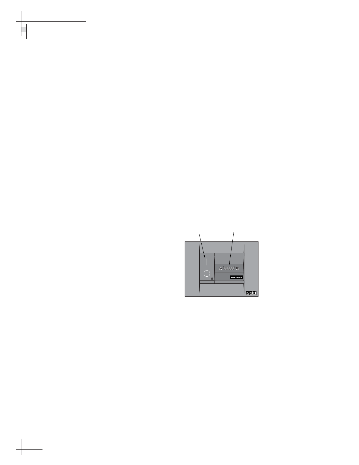
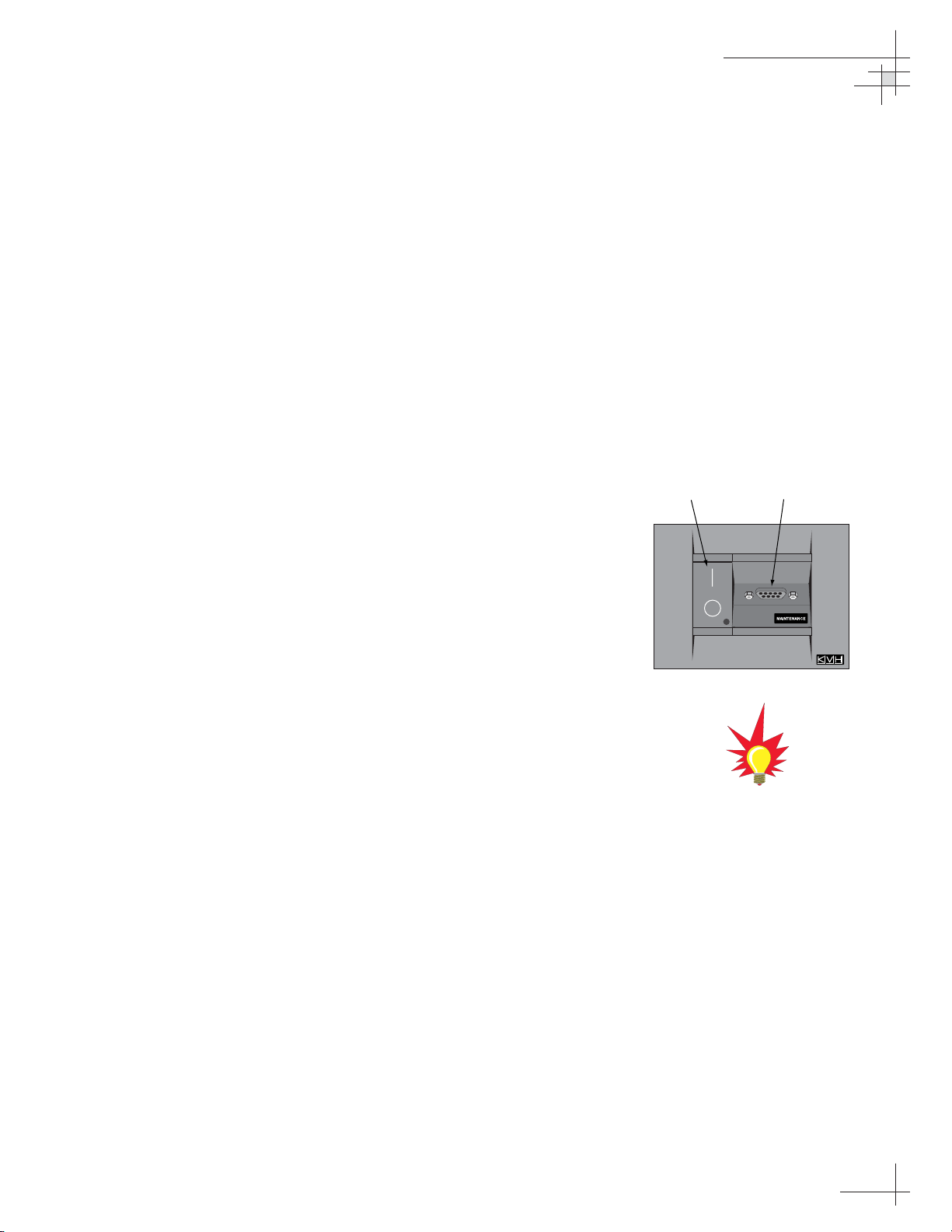
Figure 2-17
Switchplate Front Panel
Antenna
On/Off Switch
Maintenance
Port
Page 35
Are the Satellites You Want to Track Listed in the Library?
If the satellites you want to track are listed in the library, skip to
“Installing Your Satellites” on page 36.
If you want to track a satellite that is not listed in the library,
follow the steps in the next section, “Programming User-defined
Satellites.”
Programming User-defined Satellites
The TracVision 6 satellite library has the capacity for two userdefined satellites in case you want to track a satellite that is not
currently preprogrammed in the library. To configure a userdefined satellite, information about the satellite must be
provided, including:
• Satellite name
• Satellite position (longitude)
• Transponder information for each of the following
polarizations/frequencies:
- vertical high & vertical low
- horizontal high & horizontal low
or
- right
- left
• Transponder information includes:
- frequency
- symbol rate
- FEC code, and
- network ID (in hexidecimal format)
• Decoder type
This information can be obtained from your satellite service
provider or from sites on the Internet, such as www.satcodx.com.
Installation
54-0166
31
How to tell the difference between
High and Low bands:
High: 11.700 - 12.750 GHz
Low: 10.700 - 11.700 GHz
For your reference, the satellite
configuration information for the
predefined satellites is available on
our web site at
www.kvh.com/
footprint
.
Page 36
Entering User-defined Satellite Data
To configure your user-defined satellites, follow the steps below.
1. Using your PC’s terminal emulation program, type
HALT<cr> (<cr> indicates a carriage return/ENTER
key). This command puts the antenna in Idle mode.
2. Enter the
SATCONFIG parser command:
Command: SATCONFIG,USERX,YYY,Z,D,L<cr>
Where: X = 1 (USER1 satellite) or 2 (USER2 satellite)
YYY = longitude (0-180)
Z = E (East) or W (West)
D = decoding type (0 = test, 1 = DSS-A,
2 = DSS-B, 3 = DVB)
L = LNB polarization (C = circular, L = linear)
Function: configures one of the user-configurable satellites
with the longitude provided
Response: if valid entry, echoes the input data
if invalid entry, returns error message
3. Type @DEBUGON<cr> to enter DEBUG mode.
4. Enter the satellite’s transponder information:
Command: @SATCONFIG,X,N,F,S,C,ID,P,B,D<cr>
Where: @SATCONFIG = directs data to the RF Board
X = satellite location (A = USER1, B = USER2)
N = satellite table # (98 = USER1, 99 = USER2)
F = frequency in MHz (either 00000 or a range from
10700 - 12700)
S = the satellite transponder symbol rate in
Mbit/second (01000 - 29999)
C = the FEC code (e.g., 12, 23, 34, 56, 67, 78)
ID = the satellite network ID in hexidecimal format
(0x####)
P = the LNB polarization (V = vertical,
H = horizontal, R = right, L = left)
B = the LNB down conversion frequency (L = low,
H = high, G = Latin America, U = USA)
D = decoding type (0 = test, 1 = DSS-A,
2 = DSS-B, 3 = DVB)
54-0166
32
TracVision 6 Technical Manual
Table 2-9
Satellite Transponder
Data Sequence
Table 2-8
SATCONFIG Parser Command
Page 37

5. Repeat Step 4 for each of the following
transponder categories:
• vertical high • vertical low
• horizontal high • horizontal low
OR
• right • left
TracVision 6 requires that the data fields for all
transponder categories be provided. If the selected
satellite does not have information for one or more of
the transponder categories, default information should
be entered in the fields as follows:
Transponder Data Default Value
Frequency 00000
Symbol Rate 27500
FEC Code the same value as provided for those
transponders with data
Network ID 0x0000
Polarity and Band whichever combinations are not
already provided
6. Type ZAP<cr> to restart the antenna.
7. If you need to configure a second user-defined
satellite, repeat this procedure starting with Step 1
to enter data for the USER2 satellite.
You have now added your user-defined satellite(s) to the
system’s satellite library.
If you want the antenna to track one or both of these user-defined
satellites, you will now need to install it. To install a satellite, use
the
SATINSTALL command, as described in ”Installing Your
Satellites” on page 36.
The next two pages provide examples of the user-defined satellite
configuration process.
Installation
54-0166
33
Table 2-10
Satellite Transponder
Default Data
Page 38
An Example of Configuring a User-defined Satellite (N. America)
The following is an example of configuring the fictional
YOURSAT 123 as the USER1 configured satellite. Prior to
configuring this satellite or any others, be certain to get the most
up-to-date information from one of the sources previously
discussed.
YOURSAT 123 at 122 West, DVB decoder, Circular Polarization LNB
Right
Frequency 12.225 GHz
Symbol Rate 20000
FEC Code 5/6
Network ID 4100(dec) = 0x1004
Left
Frequency 12.456 GHz
Symbol Rate 20000
FEC Code 5/6
Network ID 4100(dec) = 0x1004
Based on this information, the data entered via the PC would
look like this:
HALT
SATCONFIG,USER1,122,W,3,C
@DEBUGON
@SATCONFIG,A,98,12225,20000,56,0x1004,R,U,3
@SATCONFIG,A,98,12456,20000,56,0x1004,L,U,3
@SAVE,A
ZAP
54-0166
34
TracVision 6 Technical Manual
Page 39

An Example of Configuring a User-defined Satellite (Europe)
The following is an example of configuring the fictional
YOURSAT 123 as the USER1 configured satellite. Prior to
configuring this satellite or any others, be certain to get the most
up-to-date information from one of the sources previously
discussed.
Yoursat 123 at 7 West, DVB decoder, Linear Polarization LNB
Horizontal High
Frequency 11.966 GHz
Symbol Rate 27500
FEC Code 3/4
Network ID 2048(dec) = 0x0800
Vertical High
Frequency 11.823 GHz
Symbol Rate 27500
FEC Code 3/4
Network ID 2048(dec) = 0x0800
Vertical Low
No Data Listed
Horizontal Low
No Data Listed
Based on this information, the data entered via the PC would
look like this:
HALT
SATCONFIG,USER1,7,W,3,L
@DEBUGON
@SATCONFIG,A,98,11966,27500,34,0x0800,H,H,3
@SATCONFIG,A,98,11823,27500,34,0x0800,V,H,3
@SATCONFIG,A,98,00000,27500,34,0x0000,V,L,3
@SATCONFIG,A,98,00000,27500,34,0x0000,H,L,3
@SAVE,A
ZAP
Installation
54-0166
35
Page 40

Installing Your Satellites
To install the satellites you want to track, follow the steps below.
1. Using your PC’s terminal emulation program, type
HALT<cr> (<cr> indicates a carriage return/ENTER
key). This command puts the antenna in Idle mode.
2. Enter the
SATINSTALL parser command:
Command: SATINSTALL,<sat_a_name>,<sat_b_name><cr>
Where: <sat_a_name> = the name of your choice for
Satellite A
<sat_b_name> = the name of your choice for
Satellite B
Table 2-11 lists the assigned names for satellites
that are in the preprogrammed satellite library. If
you only want to install and track one satellite,
enter
NONE as the name of Satellite B.
3. Once you’ve assigned satellites as Satellite A and
Satellite B, you need to tell the antenna which of
the two satellites it should initially acquire and
track. This step should be performed the first time
a satellite is selected, allowing the system to
download the channel guide. To do so, enter the
following parser command:
Command: @L,A or B<cr>
Where: A = track Satellite A
B = track Satellite B
4. Type ZAP<cr> to restart the antenna.
Examples:
To select Astra 2S and Hotbird for your satellite pair, and to track
Hotbird, you would enter the following commands:
SATINSTALL,ASTRA2S,HOTBIRD<cr>
@L,B<cr>
ZAP<cr>
To select and track the USER1 satellite, which you programmed
earlier into the library, you would enter the following commands:
SATINSTALL,USER1,NONE<cr>
@L,A<cr>
ZAP<cr>
54-0166
36
TracVision 6 Technical Manual
Satellite Install Name
North American Satellites
DSS 101ºW DSS_101
DSS 119ºW DSS_119
EchoStar 61ºW Echo_61
EchoStar 110ºW Echo_110
EchoStar 119ºW Echo_119
EchoStar 148ºW Echo_148
ExpressVu Expressvu
ExpressVu TV ExpressTV
European Satellites
ASTRA1 19.2ºE ASTRA1
ASTRA2N 28.2ºE ASTRA2N
ASTRA2S 28.2ºE ASTRA2S
Hispasat 30.0ºW HISPASAT
Hotbird WB 13.0ºE HOTBIRDWB
Sirius 5.0ºE SIRIUS
Thor 0.8ºW THOR
Arabsat 26ºE ARABSAT
Nilesat 7ºW NILESAT
Latin American Satellites
Galaxy 3CN 95ºW GALAXY3CN
Galaxy 3CS 95ºW GALAXY3CS
PAS 9 58ºW PAS_9
Other Installation Designations
User-defined 1 USER1*
User-defined 2 USER2*
None None
* USER1 and USER2 will only be
available if one or two user-defined
satellites have been added to the
library as detailed in
“Programming
User-defined Satellites.”
Table 2-11
Satellite Installation Names
Page 41
2.8 Setting the Skew Angle
(European Systems Only)
To optimize channel reception, the antenna’s LNB skew angle
must be adjusted. Refer to your satellite service provider for the
proper skew angle for your selected satellite service and
geographical location.
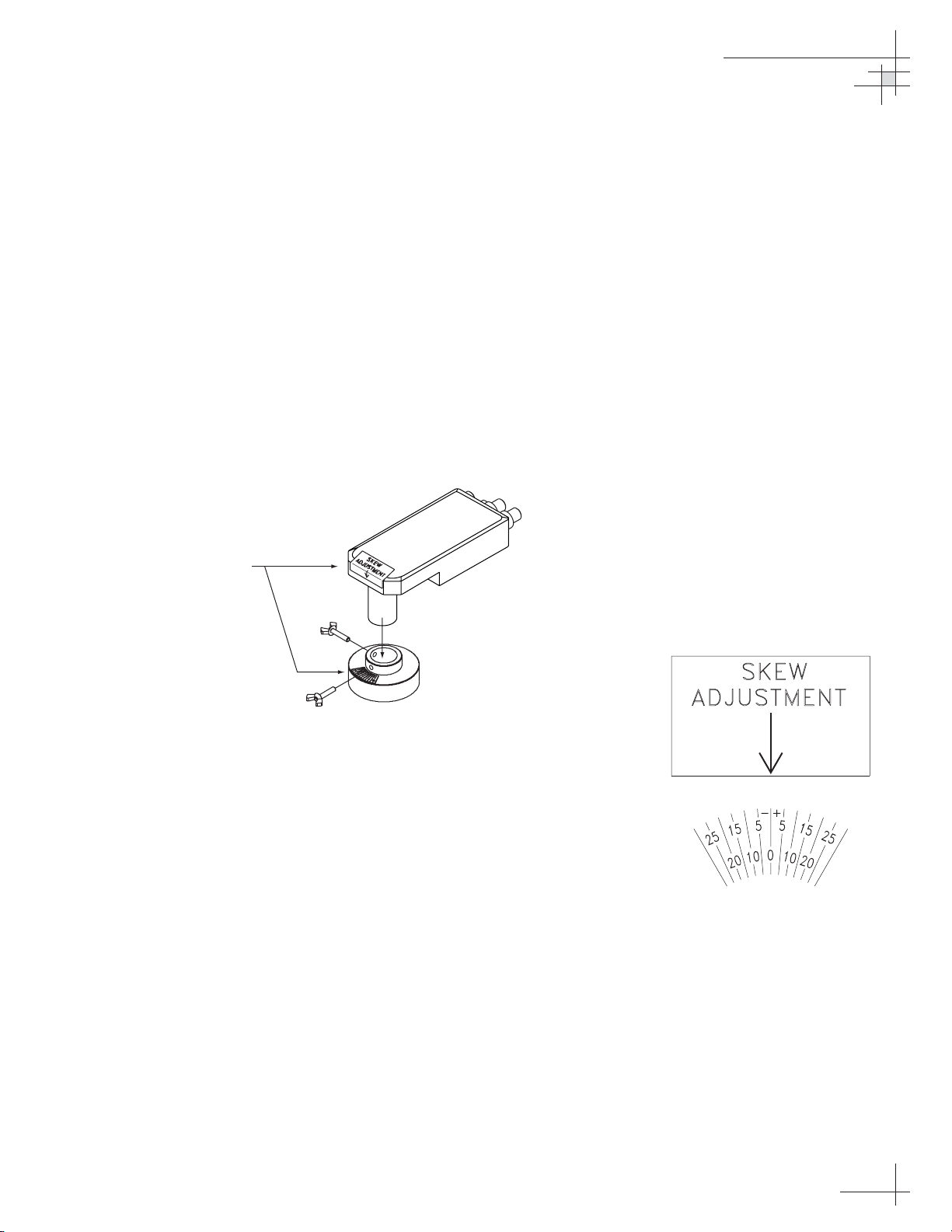
Adjusting the LNB Skew Angle
1. Turn off the power to the antenna unit.
2. If the radome is not already removed, remove the
radome and set it aside in a safe place.
3. Loosen the two wing screws securing the LNB
within the choke feed as illustrated in Figure 2-18.
4. Refer to the LNB skew angle labels on the end of
the LNB and on the LNB choke feed (shown in
Figure 2-19) and adjust the LNB as necessary to
match as closely as possible the skew angle
provided by your service provider.
5. Retighten the wing screws.
6. Reinstall the radome. Align the three radome
screw holes with the baseplate nut holders, insert
the #10-24 screws and tighten. Install a protective
plastic screw cap over each screw.
Installation
54-0166
37
Figure 2-19
Skew Angle Labels
Figure 2-18
Adjusting the European
LNB Skew Angle
Skew Labels
Page 42

2.9 Checking Out the System
Now that you’ve installed the TracVision 6, you need to verify
that the system functions properly. Check the system startup
sequence to ensure that the system is operating within normal
parameters.
To view the startup sequence, connect a PC to the switchplate’s
maintenance port. The diagnostics procedure requires Windows
Hyperterminal (or other terminal emulation software, such as
PROCOMM). Use the settings appropriate to your application
and follow the steps below.
1. Connect one end of the PC data cable to the DB9
connector on the switchplate. Connect the other
end to the serial port on your PC (a 9-pin/25-pin
connector adapter may be needed for some PCs).
2. Open the terminal emulation software and
establish the following settings:
• Bits per second: 9600
• Data bits: 8
• Parity: None
• Stop bits: 1
• Flow control: None
3. Apply power to the TracVision 6 system and allow
the system to complete full initialization. Data
should be scrolling on the PC display to identify
any system problems detected. If no data is seen,
recheck your connections and the terminal
software setup for the correct COM port.
54-0166
38
TracVision 6 Technical Manual
Figure 2-20
Switchplate Front Panel
A sample startup sequence has
been provided in
Appendix D on
page 79
with the typical ranges and
responses for the TracVision 6
during startup and operation.
Antenna
On/Off Switch
Maintenance
Port
Page 43
4. After completing the review of the startup and
operational routines, turn on the IRD and television
and check the channels on the selected satellites.
For European systems, check both horizontally and
vertically polarized channels, if possible.
5. When all checks are completed, shut down the
system.
Installation
54-0166
39
Be certain to fill out and submit the
warranty card to KVH to ensure
that your TracVision 6 is fully
covered under the 2-year parts and
1-year labor warranty.
Page 44

2.10 Changing Geographic Location
If you move to a different geographic area, you will need to
modify your TracVision 6 system to receive satellite TV signals in
the new location. To begin receiving satellite signals in the new
area, perform the following steps.
Swap LNBs
To receive the proper satellite signals in the new geographic
location, your TracVision antenna must be equipped with the
appropriate LNB for that location. If moving to the U.S., you will
need to install a North American-style LNB; if moving to Europe,
you will need to install a European-style LNB; and if moving to
Latin America, you will need to install a Latin American-style
LNB. Table 2-12 lists the part numbers for ordering these LNB
options.
Part Name Part Number
North American LNB Replacement Kit 02-1033-01
Latin American LNB Replacement Kit 02-1033-04
European Quad-output LNB Replacement Kit 02-1033-03
European Dual-output LNB Replacement Kit 02-1033-02
With the new part, you will receive a simple instruction sheet for
swapping the LNBs.
Install New Satellites
When you move to a new area, the list of available satellites
changes. If you’re moving to Europe, you will need to choose a
new satellite pair from the list of available European satellites
(see Table 2-7). If you’re moving to the U.S., you will need to
choose a new satellite pair from the list of available North
American satellites (see Table 2-6). And if you’re moving to Latin
America, you will need to select a Latin American satellite. For
details on installing these new satellites, refer to Section 2.7,
“Installing Satellites to Track” on page 29.
Replace the IRD
In order to receive satellite TV service in your new geographic
location, you will need to purchase an IRD designed for that
location. Refer to your satellite TV service provider for details.
54-0166
40
TracVision 6 Technical Manual
Table 2-12
LNB Part Numbers
You may also need to replace your
television when changing
geographic location. In North
America, your TV must support the
NTSC video standard. In Europe,
your TV must support the PAL
video standard.
Page 45

Troubleshooting
54-0166
41
3 – Troubleshooting
This section identifies basic trouble symptoms and lists their possible
causes and solutions.
Contents
3.1 Troubleshooting Matrix . . . . . . . . . . . . . . . . . . . . . . . . . . . . . . . . .43
3.2 Causes and Remedies for Common
Operational Issues . . . . . . . . . . . . . . . . . . . . . . . . . . . . . . . . . . . . .44
3.3 IRD Troubleshooting . . . . . . . . . . . . . . . . . . . . . . . . . . . . . . . . . . .46
3.4 Antenna Gyro and LNB Faults . . . . . . . . . . . . . . . . . . . . . . . . . . . .46
3.5 Computer Diagnostics . . . . . . . . . . . . . . . . . . . . . . . . . . . . . . . . . .47
3.6 Maintenance Port Parser Commands . . . . . . . . . . . . . . . . . . . . . .47
Page 46

Troubleshooting
54-0166
43
3.1 Troubleshooting Matrix
The troubleshooting matrix shown in Table 3-1 identifies some
trouble symptoms, their possible causes, and references to
troubleshooting solutions.
Table 3-1
Troubleshooting Matrix
Section 3.2
Key
1 = Anyone can do
2 = Electronics know-how recommended
3 = Dealer service recommended
U
L
O
S
D
N
A
(
w
E
o
S
p
U
w
A
o
l
C
,
E
e
s
L
u
B
f
I
S
S
SYMPTOM
Antenna non-functional 1
Antenna not switching satellites 1 1 1 1 2 2 2 2
No picture on TV set 1 1 2 2 2 2 2
Certain channels do not work 1 1 1 3 2 2 2
Intermittent picture for short intervals 1 1 1 2 2 2 3 2
O
P
l
n
e
s
w
s
o
l
e
B
V
g
n
i
)
r
i
N
w
O
I
r
e
T
p
o
r
p
m
i
r
o
,
r
e
g
n
i
r
u
d
g
n
i
n
r
u
t
c
e
r
r
o
c
n
I
n
o
p
i
t
u
t
a
r
r
u
a
t
g
i
s
f
n
o
c
e
t
i
l
l
l
a
e
t
n
a
g
i
s
s
t
e
t
i
l
l
e
t
a
S
S
e
d
u
e
s
k
s
i
c
o
l
b
e
t
i
l
l
e
t
a
e
e
c
g
n
a
e
r
r
e
e
f
v
r
o
c
R
e
r
e
f
t
n
e
i
t
i
l
r
l
a
e
t
d
a
a
S
d
s
r
e
o
g
t
n
c
a
e
h
n
c
n
a
t
a
d
y
c
n
e
o
u
o
l
q
r
o
t
c
e
r
r
o
c
y
n
I
T
d
o
e
c
s
F
R
e
s
w
s
i
t
l
u
m
f
o
e
p
e
u
p
h
o
r
c
t
p
i
m
i
r
o
y
t
l
u
n
a
n
f
e
t
D
n
R
I
A
)
3
.
3
n
o
i
t
c
e
S
(
d
e
r
u
g
i
f
n
n
o
o
i
t
c
c
y
e
l
r
S
(
y
t
l
u
a
f
o
b
r
y
m
g
e
s
a
s
a
B
N
L
)
)
4
.
4
.
3
3
n
o
i
t
c
e
S
(
y
t
l
u
a
f
y
l
System works at dock but not on the move 1 3
System will not find satellite 11111232 2 2 3 2
Snowy television picture 1 2 2
Pixelating television picture 1 1 2 2 2 3 2
Page 47

54-0166
44
TracVision 6 Technical Manual
3.2 Causes and Remedies for
Common Operational Issues
There are a number of common issues that can affect the
performance of the TracVision 6. The following sections address
these issues and potential solutions.
Blown Fuse, Low Power, or Improper Wiring
Blown Fuse
The antenna unit is equipped with two fuses
mounted on its main printed circuit board (PCB).
If either of these fuses has blown or been broken,
the system will not work. For details on replacing
an antenna unit fuse, refer to Section 5.4, “Replacing
the PCBs and Fuses” on page 54.
Low Power
If the power cable to the switchplate is more than
50 ft (15 m) long, the power level can decrease
over the course of the cable, resulting in a voltage
level at the antenna unit that is too low to power
the system. Refer to “Connecting the Switchplate to
Vessel Power” on page 25 for details on supplying
adequate power to the antenna unit.
Wiring
If the system has been improperly wired, the
antenna unit will not operate correctly. Refer to
Section 2.4, “Wiring the Switchplate” on page 23 for
complete system wiring information.
Vessel Turning During Startup
If the vessel turns during the 60-second startup sequence that
occurs immediately after turning on the power to the
TracVision 6, the antenna gyro will record that variable motion
as “standing still.” This may cause the antenna to track
improperly. To solve this problem, turn the TracVision 6 off for
at least 10 seconds. Turn the system back on, ensuring that the
vessel is either motionless or traveling in a straight line for the
60 seconds immediately following power-up.
Page 48
Incorrect Satellite Configuration
(European Systems Only)
The satellite configuration on European IRDs must match the
satellite settings on the TracVision 6 system.
• Satellite A on the TracVision 6 must be the same
satellite as IRD Alternative 1 (or A, based on your
IRD) and must be assigned the IRD DiSEqC 1
setting.
• Satellite B on the TracVision 6 must be the same
satellite as IRD Alternative 2 (or B, based on your
IRD) and must be assigned the IRD DiSEqC 2
setting.
Refer to your IRD user manual for complete instructions on
configuring your IRD.
Satellite Signal Blocked
Satellite signals can be blocked or degraded by buildings, other
vessels, or equipment on the vessel itself. Refer to “Choosing the
Best Location for the TracVision Antenna” on page 12 to make certain
that the TracVision 6 antenna unit is in the optimal location.
Simply moving the vessel to clear an external obstruction will
also restore signal quality.
Satellite Coverage Issue
TracVision 6 will provide outstanding reception within the
24" (60 cm) antenna coverage area for your satellite television
service of choice. However, signal quality can be degraded as you
approach the fringe coverage areas. Refer to your satellite
television service manual to check the viable coverage area for a
24" (60 cm) antenna.
Radar Interference
The energy levels radiated by radar units can overload the
antenna’s front-end circuits. Refer to “Choosing the Best Location
for the TracVision Antenna” on page 12 to make certain that the
TracVision 6 antenna unit is in the optimal location with regard
to your radar unit.
Troubleshooting
54-0166
45
For your convenience, KVH
provides links to several web sites
that offer satellite coverage
information. Simply go to our web
site at
www.kvh.com/footprint
.
Page 49

Satellite Frequency Data Changed
If some channels work, while one or more other channels do not,
or the antenna cannot find the satellite, the selected satellite’s
frequency data may have changed. This frequency data can be
updated via the maintenance port. Please call KVH Technical
Support for details.
Incorrect or Loose RF Connectors
As part of preventive maintenance (described in Section 4.2,
“Preventive Maintenance” on page 51) KVH recommends checking
the antenna unit’s cable connections. A loose RF connector can
reduce the signal quality. In addition, if you are unable to switch
satellites using your IRD remote, make sure that your IRD’s RF
cable is connected to the antenna baseplate connector labeled
“RF1” (see Section 2.3, “Connecting the IRD(s)” on page 19).
Type of Multiswitch Used
An active (not passive) multiswitch must always be used to
connect the TracVision 6 system to multiple IRDs. Refer to
Section 2.3, “Connecting the IRD(s)” on page 19 for directions on
proper multiswitch/multiple IRD cabling.
Do not use a multiswitch with a European dual-output LNB
system. Due to the signal polarization of European satellites, the
use of a multiswitch with a dual-output LNB will result in a loss
of signal and less than optimal operation.
3.3 IRD Troubleshooting
The IRD that was provided with your satellite television service
may also be the cause of less-than-ideal operation. First check the
IRD’s configuration to ensure it is set up for the desired
programming. In the case of a faulty IRD, refer to your IRD user
manual for service and warranty information. If the IRD is both
configured properly and fully functional, contact your local KVH
dealer or service center for assistance.
3.4 Antenna Gyro and LNB Faults
Section 4, “Maintenance” on page 49 provides detailed instructions
for authorized service personnel who may be required to replace
the TracVision 6 antenna gyro or LNB.
54-0166
46
TracVision 6 Technical Manual
Page 50
3.5 Computer Diagnostics
TracVision 6 has been designed to provide diagnostic readouts
viewed on a PC having an RS-232 serial communication port. If
you are unable to isolate a system problem, set up for computer
diagnostics as described below. System problems will most likely
be found somewhere through the diagnostic readouts.
The diagnostics procedure requires Windows Hyperterminal (or
other terminal emulation software, such as PROCOMM). Use the
settings appropriate to your application and follow the steps
below.
1. Connect one end of the PC data cable to the DB9
connector on the switchplate. Connect the other
end to the serial port on your PC (a 9-pin/25-pin
connector adapter may be needed for some PCs).
2. Open the terminal emulation software and
establish the following settings:
• Bits per second: 9600
• Data bits: 8
• Parity: None
• Stop bits: 1
• Flow control: None
3. Apply power to the TracVision 6 system and allow
the system to complete full initialization. Data
should be scrolling on the PC display to identify
any system problems detected. If no data is seen,
recheck your connections and the terminal
software setup for the correct COM port.
3.6 Maintenance Port Parser
Commands
TracVision 6 system parser commands are detailed in
Appendix E on page 81.
Troubleshooting
54-0166
47
Figure 3-1
Switchplate Front Panel
Appendix D on page 79
shows the
diagnostic information available in
the startup data sequence.
Antenna
On/Off Switch
Maintenance
Port
Page 51

Maintenance
54-0166
49
4 – Maintenance
This section identifies system components that may be replaced in the
field, details how to replace those components, and lists preventive
maintenance routines.
Contents
4.1 Warranty/Service Information . . . . . . . . . . . . . . . . . . . . . . . . . . . .51
4.2 Preventive Maintenance . . . . . . . . . . . . . . . . . . . . . . . . . . . . . . . . .51
4.3 TracVision 6 Field Replaceable Units . . . . . . . . . . . . . . . . . . . . . . .52
4.4 Replacing the PCBs and Fuses . . . . . . . . . . . . . . . . . . . . . . . . . . .54
4.5 Replacing the Antenna Gyro Assembly . . . . . . . . . . . . . . . . . . . . .58
4.6 Replacing the Azimuth Limit Switch Assembly . . . . . . . . . . . . . . .61
4.7 Replacing the Elevation Motor or Belt . . . . . . . . . . . . . . . . . . . . . .63
4.8 Replacing the LNB . . . . . . . . . . . . . . . . . . . . . . . . . . . . . . . . . . . . .65
4.9 Preparation for Shipment . . . . . . . . . . . . . . . . . . . . . . . . . . . . . . .67
Page 52
Maintenance
54-0166
51
4.1 Warranty/Service Information
For information on KVH warranty, repair, and liability policies,
please refer to the complete warranty statement provided at the
conclusion of this manual. If you have any questions, please call
your local authorized dealer/installer or distributor, or contact
KVH or KVH Europe directly.
IMPORTANT! Before returning the product, be sure to obtain
an RMA number from KVH’s Technical Support Department
and write the number on the outside of the box. Shipments
received without an RMA number will be returned to you at
your expense.
4.2 Preventive Maintenance
TracVision 6 requires minimal preventive maintenance. The
following tasks are sufficient to maintain peak performance.
Monthly
• Wash the exterior of the radome and baseplate
assembly with fresh water; a mild detergent may
be added to remove grime. Use caution when
spraying the radome directly with high-pressure
water.
• Do not apply abrasive cleaners or volatile solvents
such as acetone to the ABS radome.
• Check all connectors at the antenna baseplate and
IRD. Remove connectors and examine for signs of
corrosion; clean as needed.
Semi-Annually
• Remove the radome and examine the interior of
the antenna unit for signs of corrosion, loose
connections, or frayed or broken wires.
When cleaning the radome, avoid
any compounds that react with
plastic.
Detailed information on KVH’s
global support program and how to
contact KVH or a dealer near you is
available at www.kvh.com/
global_support.
Page 53

54-0166
52
TracVision 6 Technical Manual
4.3 TracVision 6 Field
Replaceable Units
If you experience an operating problem or otherwise require
technical assistance, please contact your local authorized
TracVision 6 dealer/installer or distributor. If an authorized
dealer/installer or distributor is not located nearby, contact KVH
or KVH Europe directly at the telephone, fax, or e-mail listings
on the first page of this manual.
Replacement part numbers for field replaceable units (FRUs) that
can be serviced in the field are listed in Table 4-1. These parts
may be obtained from any KVH authorized dealer/installer or
may be ordered directly from KVH.
FRU Part Number
Radome 02-1047-01
Switchplate 02-1023
Main PCB 02-0992
RF PCB 02-1342
Antenna Gyro Sensor 02-1090
Antenna Gyro Gasket 24-0139
Elevation Drive Belt 24-0105-83
Elevation Motor 02-1356
Azimuth Limit Switch Assembly 02-0957-01
North American LNB 02-0870
Latin American LNB 02-0870-01
European Quad-output LNB 02-1263
European Dual-output LNB 02-1278
Data Cable 32-0619-100
RF Cable 32-0566-100
PC Cable 32-0628-06
Power Cable 32-0510-100
Ground Cable 32-0583-50
CPU Fuses 16-0017-3150
The serial number for your
TracVision 6 will be required during
any troubleshooting or service calls.
You will find the serial number on
the first page of this manual.
Table 4-1
TracVision 6 Field
Replaceable Units
To help us continually improve the
quality and reliability of our
systems, please return any failed
component to KVH or KVH Europe
(care of the mailing address listed
on the first page of this manual)
after you receive your replacement
part.
Page 54

The antenna unit’s printed circuit boards (PCBs), gyro, azimuth
limit switch, LNB, elevation motor, and elevation drive belt may
be removed and replaced on site using common hand tools.
Other TracVision 6 service must be done by your authorized
dealer/installer, distributor or by KVH. Evidence of tampering or
unauthorized repairs will void the warranty. The following
sections provide step-by-step procedures for removing and
replacing field replaceable units.
Figure 4-1 depicts the location of a number of components within
the TracVision 6 antenna unit.
Maintenance
54-0166
53
TracVision 6 components receive
power from multiple sources. Do
not open any electrical
assemblies or attempt servicing
until IRD power and vessel input
power are disconnected.
Figure 4-1
TracVision 6 Antenna Unit
(Baseplate Cut Away)
European
Quad-output
LNB
European
Dual-output
LNB
Elevation Motor
and Drive Assembly
PCB Cover
and PCBs
Azimuth Limit
Switch Assembly
Tie-wraps
North American/
Latin American LNB
Antenna Gyro
Azimuth Motor
Page 55
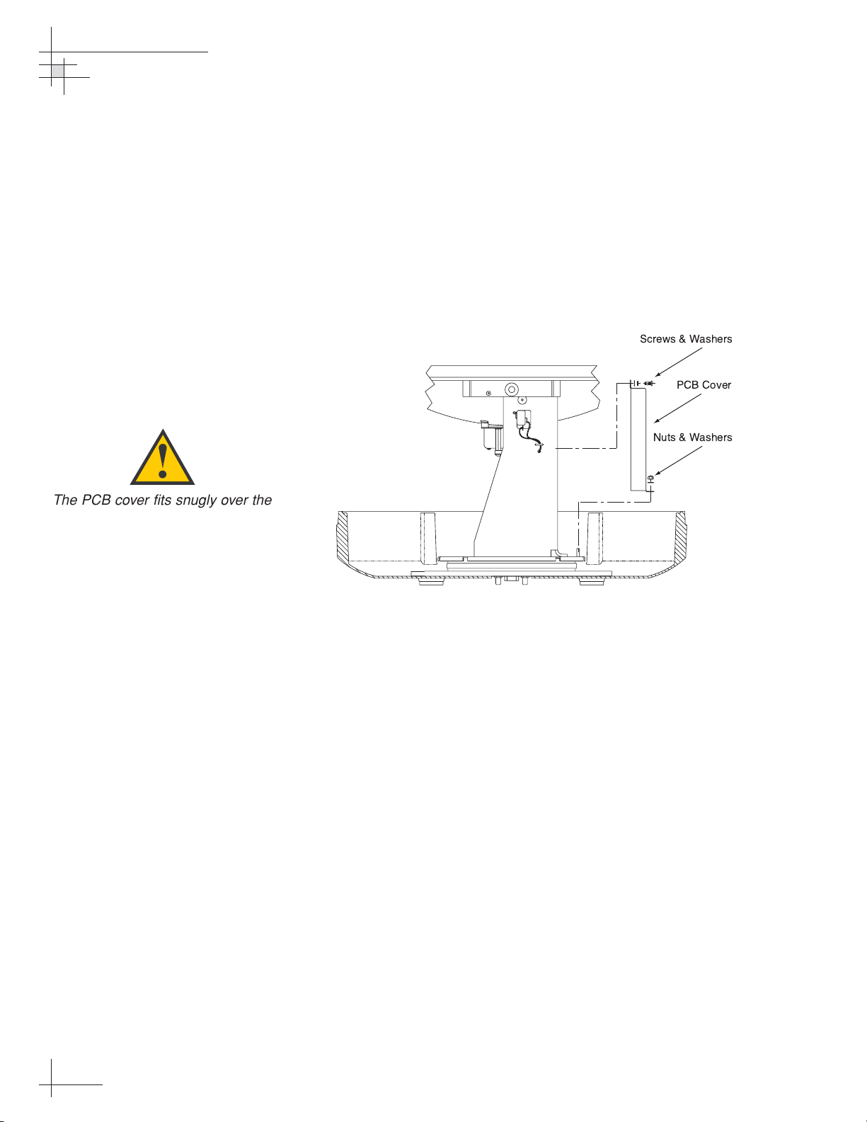
4.4 Replacing the PCBs and Fuses
The main and RF PCBs are protected by a cover fastened to the
antenna support frame. This cover must be removed to gain
access to the PCBs and fuses discussed in the following sections.
Removing the PCB Cover
1. Using a 3⁄8" nut driver/socket, remove the three
nuts and washers from the PCB cover’s bottom
flange.
2. Remove the three Phillips screws and washers
from the PCB cover’s upper flange.
3. Remove the PCB cover and set aside.
54-0166
54
TracVision 6 Technical Manual
Figure 4-2
PCB Cover Removal
The PCB cover fits snugly over the
PCBs. When removing or replacing
the cover, take care to ensure that
the cover does not dislodge any of
the Molex connectors, as this will
cause system errors and improper
operation.
Screws & Washers
PCB Cover
Nuts & Washers
Page 56
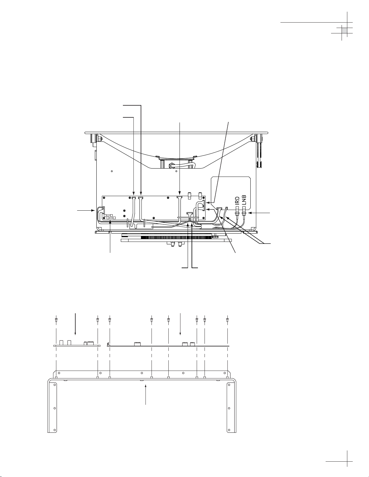
The PCBs are mounted to the antenna support frame with
machine screws and are interconnected by Molex connectors.
Figure 4-3 shows the PCB arrangement and connectors, while
Figure 4-4 shows how the printed circuit boards are mounted to
the support frame. Refer to these figures when replacing the
PCBs.
Maintenance
54-0166
55
Figure 4-4
PCB Mounting (Top View)
Figure 4-3
PCB Connector Locations
(Rear View)
Elevation Motor
Power/Data
Azimuth Motor
MAIN PCB
Fuses
Cable Wrap
Azimuth Limit
Switch
to RF PCB
RF PCB
RF Connectors
to Main PCB
Antenna Gyro
Elevation Limit
Switch
RF PCB Main PCB
Support Frame
Page 57

54-0166
56
TracVision 6 Technical Manual
Replacing the Main PCB
1. With a PC connected to the switchplate’s
maintenance port, apply power to the antenna unit.
2. Record the system serial number for later re-entry
(the serial number is listed at the beginning of the
startup sequence, as shown in Appendix D on
page 79).
3. Disconnect power from the antenna unit and the
IRD.
4. Remove the PCB cover, as explained in “Removing
the PCB Cover” on page 54.
5. Disconnect all Molex connectors from the main PCB
(see Figure 4-3).
6. Remove the nine #6-32 screws that secure the PCB
to the antenna frame (see Figure 4-4).
7. Remove the PCB from the antenna frame.
8. Reverse this process to install the replacement
PCB. Reconnect all connectors removed in Step 5.
9. Reinstall the PCB cover.
10. Apply power to the antenna unit.
11. Type
HALT<cr> (<cr> indicates a carriage return/
ENTER key).
12. Type
DEBUGON<cr>.
13. Type
=TVG6HP<cr>.
14. Type
=SERNUM,<serial number><cr>, where
<serial number> = the system serial number you
recorded in Step 2.
15. Type
ZAP<cr> to restart/reinitialize the system.
16. Calibrate the antenna gyro as explained in
“Calibrating the Antenna Gyro” on page 59.
17. Reinstall your selected satellites as directed in
Section 2.7, “Installing Satellites to Track” on page 29.
Refer to Section 3.5, “Computer
Diagnostics” on page 47 for
complete details on connecting a
PC to the system via the
maintenance port.
Page 58
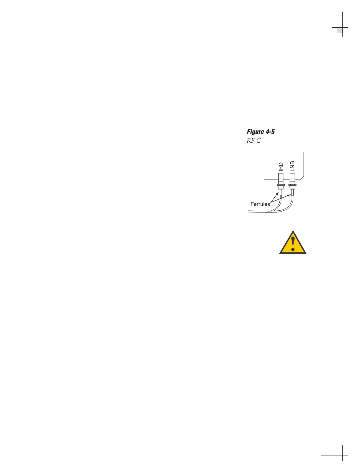
Maintenance
54-0166
57
Replacing the RF PCB
1. The RF PCB receives operating voltages from both
the main PCB and the IRD (via the RF cable).
Ensure that all power (including the IRD) is
turned off before proceeding.
2. Remove the PCB cover, as explained in “Removing
the PCB Cover” on page 54.
3. Disconnect the two Molex connectors from the RF
PCB (see Figure 4-3 on page 55).
4. If one of the RF cables is not already marked, label
one so that the RF cables can later be plugged into
the proper positions on the new RF PCB.
5. Using a
7
⁄16" wrench, carefully remove the two RF
cables from the RF PCB. Hold the RF connector
ferrules while loosening the connectors to avoid
excess stress on or twisting of the cables (see
Figure 4-5).
6. Remove the four #6-32 screws that secure the PCB
to the antenna frame (see Figure 4-4 on page 55).
7. Remove the old RF PCB.
8. Install the new RF PCB, making certain to align
the PCB so that the RF connectors are facing
down, as shown in Figure 4-3 on page 55.
9. Secure the RF PCB to the support frame using the
screws removed in Step 6.
10. Reattach the RF cables, making certain to connect
them in their original positions. Do not exceed
5 in-lbs of torque.
11. Reattach the Molex connectors to the RF PCB.
12. Reinstall the PCB cover.
Replacing a Fuse
Two 5x20 mm, 3.15-amp, 250-volt fast-blow fuses are mounted to
the main PCB (see Figure 4-3 on page 55). If one of these fuses
has blown or been broken, simply remove the bad fuse and
replace with a good fuse of the same rating.
Failure to hold the ferrules tightly
while loosening the RF connectors
can result in damage to the cables
and reduce the signal quality.
Figure 4-5
RF Cable Ferrules
IRD
Ferrules
LNB
Page 59
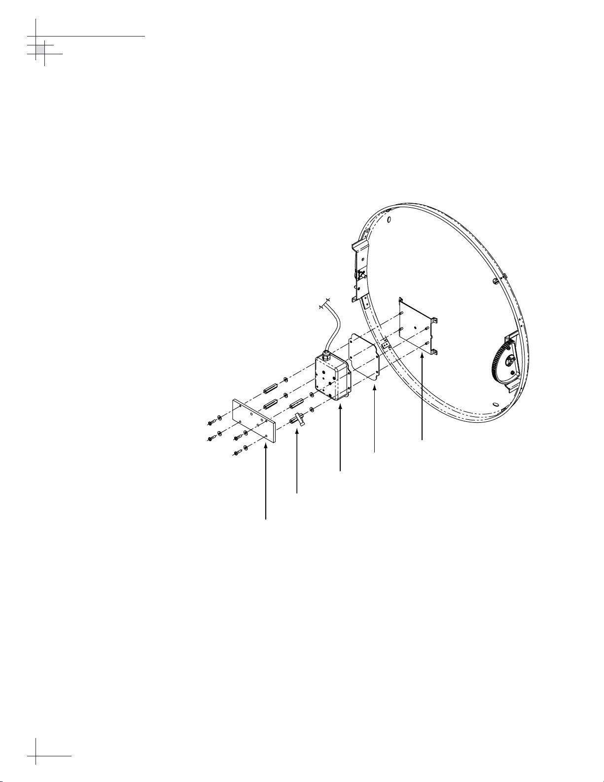
4.5 Replacing the Antenna Gyro
Assembly
1. Remove the PCB cover, as explained in “Removing
the PCB Cover” on page 54.
2. Remove the four screws, four washers, and the
counterweight from the end of the antenna gyro
(see Figure 4-6).
3. Using a
3
⁄8" nut driver/socket, remove the four
standoffs securing the antenna gyro to the reflector
bracket (see Figure 4-6). Slide the tie-wrap, which
secures the antenna gyro cable, off the bottom
right standoff.
4. Remove the 3 tie-wraps securing the gyro cable to
the RF cables (see Figure 4-1 on page 53).
5. Disconnect the antenna gyro Molex connector
from the main PCB (see Figure 4-3 on page 55).
Remove the old antenna gyro assembly.
54-0166
58
TracVision 6 Technical Manual
Figure 4-6
Replacing the Antenna Gyro
Assembly
Bracket
Gasket
Gyro
Standoffs
Counterweight
Page 60

6. Connect the new antenna gyro’s Molex connector
to the main PCB.
7. Replace the antenna gyro gasket (see Figure 4-6).
8. Using the standoffs removed in Step 3, secure the
new antenna gyro to the bracket. The antenna gyro
should be oriented so that the cable extends from
the top of the gyro, as shown in Figure 4-6.
9. Using a tie-wrap, secure the antenna gyro cable to
the bottom right standoff.
10. Reattach the counterweight, screws, and washers
removed in Step 2.
11. Redress the gyro and RF cables using 3 tie-wraps.
12. Carefully move the reflector through its range of
motion to ensure that the cable moves freely
between the elevation mechanism and the lower
assembly. Adjust the antenna gyro cable as
necessary to ensure proper motion.
13. Reinstall the PCB cover.
Calibrating the Antenna Gyro
1. With a PC connected to the switchplate’s
maintenance port, apply power to the antenna
unit.
2. Type
HALT<cr> (<cr> indicates a carriage
return/ENTER key) while the system is performing
the limit switch initialization routine. The system
will complete the initialization function by finding
the azimuth and elevation switch limits and then
go to the home position.
IMPORTANT! Record the 8-digit serial number
displayed in the startup message.
3. Type
DEBUGON<cr> to enter Debug Mode.
4. Type
CLEAREE<cr>.
5. Type
ZAP<cr> to restart/reinitialize the system.
6. Type
HALT<cr>.
7. Type
DEBUGON<cr>.
8. Type
=TVG6HP<cr>.
Maintenance
54-0166
59
Refer to Section 3.5, “Computer
Diagnostics” on page 47 for
complete details on connecting a
PC to the system via the
maintenance port.
Make sure the cable jacket passes
through the PCB access slot to
protect the wires from the edge of
the PCB frame.
When rotating the antenna by
hand, go slowly! Hitting the
mechanical stops with excessive
force will damage the azimuth limit
switch.
Page 61

9. Type HALT<cr>.
10. Type
DEBUGON<cr>.
11. Type
=LSTEST<cr>.
12. Type
EL,300<cr>.
13. Type
=CALGYRO<cr>. Verify that the Antenna
Gyro Azimuth scale factor is between -0.00090 and
-0.00110 and the Antenna Gyro Elevation scale
factor is between 0.00090 and 0.00110.
14. Type
=SERNUM,<serial number><cr>, where
<serial number> = the system serial number that
you recorded in Step 2.
15. Type
ZAP<cr> to restart/reinitialize the system.
KVH recommends that you complete the following additional
steps to speed satellite acquisition and improve system
performance:
16. Type
HALT<cr> while the system is performing
the limit switch initialization routine.
17. Determine your vessel’s current latitude and
longitude to the nearest degree.
18. Type
GPS,AA,B,CCC,D<cr> where
• AA = Latitude in degrees
• B = N (North) or S (South)
• CCC = Longitude in degrees
• D = E (East) or W (West)
19. Verify that the response shows the correct
parameters.
20. Type
ZAP to restart/reinitialize the system.
54-0166
60
TracVision 6 Technical Manual
Page 62
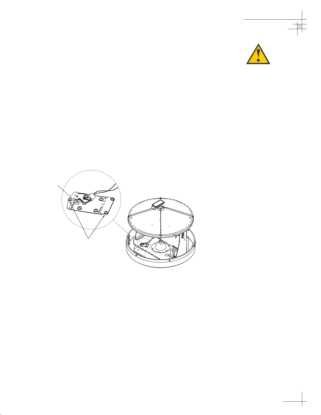
4.6 Replacing the Azimuth Limit
Switch Assembly
1. Rotate the antenna assembly, by hand, clockwise
until it stops.
2. Remove the PCB cover as explained in “Removing
the PCB Cover” on page 54.
3. At the main PCB, cut the black and white wires
from the azimuth limit switch Molex connector
(see Figure 4-3 on page 55). Leave about an inch of
the wires still connected at the Molex connector for
later reference.
4. At the azimuth limit switch cover, remove the hot
melt holding the black and white wires in place
(see Figure 4-7).
5. Remove the three #6-32 retaining screws from the
limit switch cover and set aside (see Figure 4-7).
Lift the cover to access the limit switch
underneath.
6. Remove the four #8-32 screws securing the limit
switch to the cover and set aside.
7. Replace the azimuth limit switch. Attach the new
switch to the cover using the #8-32 screws, flat
washers, and cable clamp.
Maintenance
54-0166
61
Figure 4-7
Azimuth Limit Switch Cover
When rotating the antenna by
hand, go slowly! Hitting the
mechanical stops with excessive
force will damage the azimuth limit
switch.
Hot Melt
Retaining Screws
Page 63
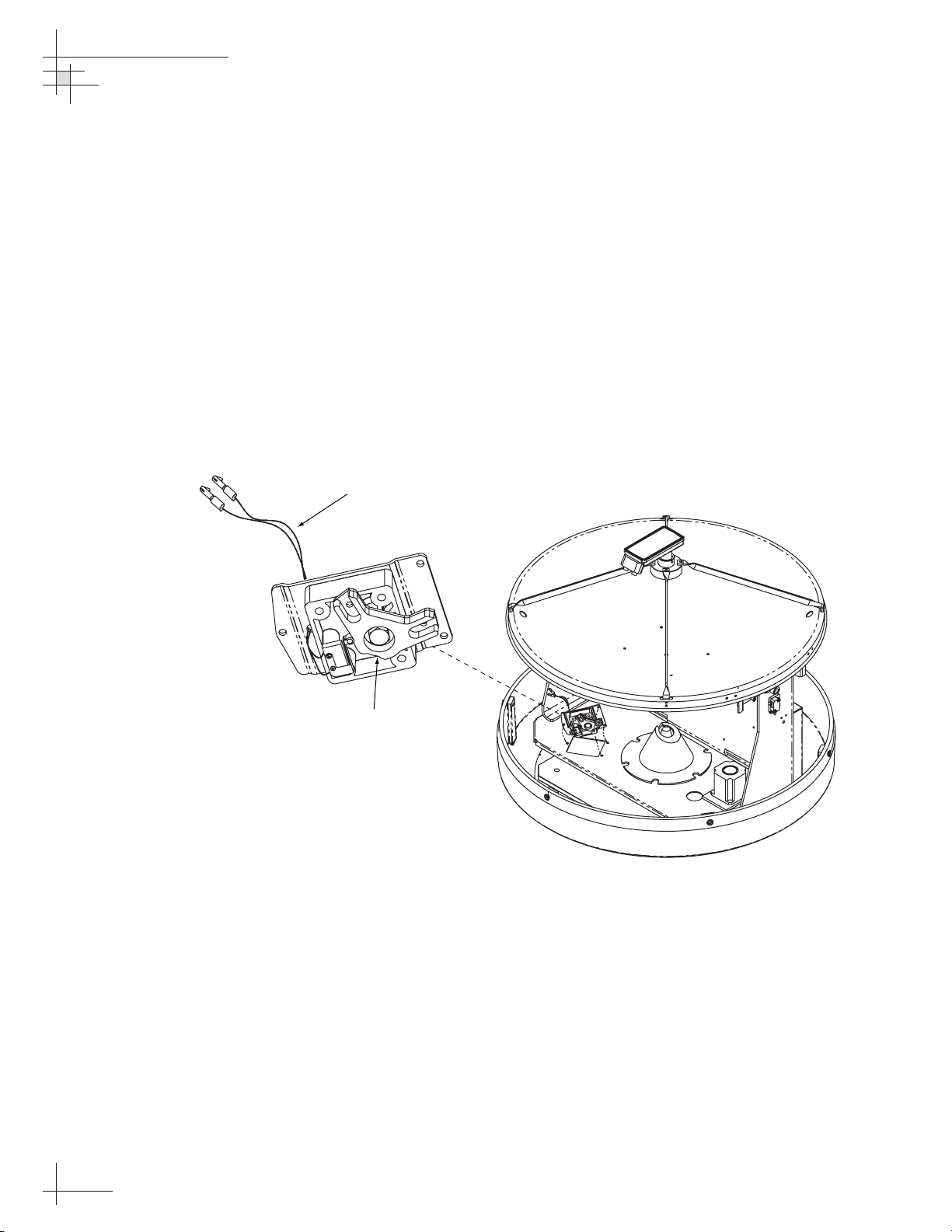
8. Route the new limit switch wires through the
cover and cable clamp to the main PCB’s Molex
connector. After noting the position of the old
black and white wires, remove the old wires from
the Molex connector. Attach the new wires in their
places.
9. Reinstall the PCB cover.
10. Before re-installing the azimuth limit switch to the
antenna assembly, orient the switch’s plastic cam
as shown in Figure 4-8. With the cam in the proper
position, reinstall the switch to the antenna
assembly using the three #6-32 retaining screws
and flat washers. Ensure the cam finger engages
the stop pin in the mounting cavity.
11. Apply hot melt or RTV at the limit switch cover’s
wire access hole to protect the wires from chafing
(see Figure 4-7).
54-0166
62
TracVision 6 Technical Manual
Figure 4-8
Azimuth Limit Switch Orientation
Black and White Wires
to Main PCB Molex Connector
Plastic Cam
Page 64
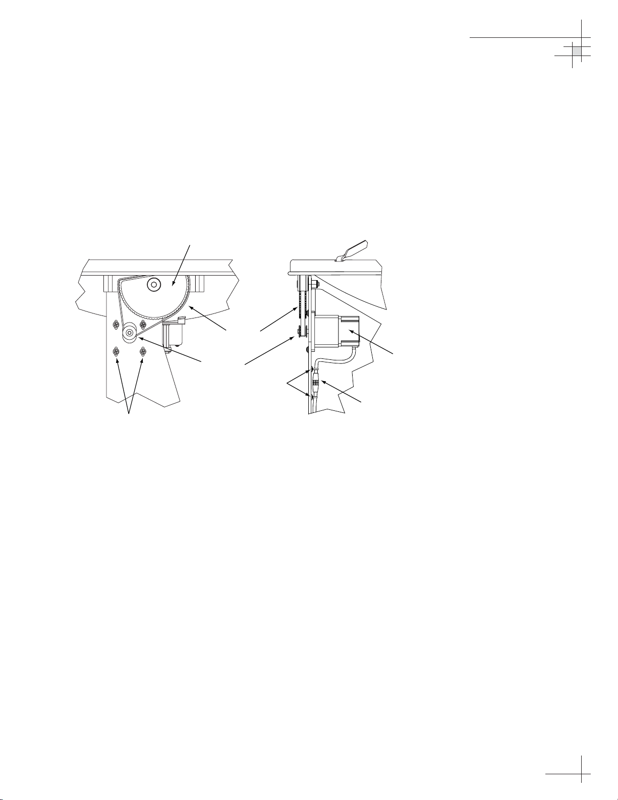
4.7 Replacing the Elevation Motor
and Belt
The elevation motor is mounted to the inside of the support
frame. Machine screws and washers hold the drive motor in
position to maintain proper tension on the toothed drive belt.
Figure 4-9 shows the arrangement of motor, drive belt, and
antenna pulley.
Replacing the Drive Belt
1. Loosen the four #8-32 Phillips screws until the
motor is free to move upward. Raise the motor to
the top of the slots and retighten the screws to
hold it there.
2. Roll the belt over the motor hub while slowly
moving the antenna reflector along its elevation
axis. Work the belt out from between the antenna
pulley and reflector.
3. Carefully work the new belt in between the
antenna pulley and the reflector. Ensure that the
teeth are on the inside of the belt. Feed the belt
over the motor hub. Once the belt is in place, work
it back and forth to ensure that the belt is aligned
and the teeth are engaged with the motor pulley.
Maintenance
54-0166
63
Figure 4-9
Elevation Drive Mechanism
Side View Front View
Pulley
Drive Belt
Motor Hub
Tie-wraps
Motor Screws and Washers
Elevation Motor
In-line Connector
Page 65

4. Loosen the screws and gently press downward on
the motor hub until the drive belt is at proper
tension. Adjust the belt tension for a maximum of
1
⁄8" (3 mm) deflection with moderate finger
pressure between the motor and antenna pulley.
Some readjustment may be necessary if the belt
tension results in excessive antenna reflector
vibration.
5. Tighten the screws.
Replacing the Elevation Drive Motor
1. Cut the top tie-wrap that secures the elevation
motor cable to the support frame (see Figure 4-9
on page 63).
2. Disconnect the elevation motor cable from the
in-line connector (see Figure 4-9).
3. Remove the four Phillips screws and washers that
secure the motor to the support frame (see
Figure 4-9). Remove the motor assembly.
4. Install the new motor assembly with the elevation
motor cable facing down, as shown in Figure 4-9.
Reinstall the screws and washers but do not
tighten.
5. Raise the motor and work the toothed drive belt
over the outer lip of the motor hub. Press down
gently on the motor body while rotating the
antenna reflector up and down to ensure free
movement.
6. Adjust the belt tension for a maximum of
1
⁄8" (3 mm) deflection with moderate finger
pressure between the motor and antenna pulley.
Some readjustment may be necessary if the belt
tension results in excessive antenna reflector
vibration.
7. Tighten the screws.
8. Connect the new elevation motor cable to the
in-line connector.
9. Secure the elevation motor cable to the support
frame using a tie-wrap at the top tie-wrap holder.
54-0166
64
TracVision 6 Technical Manual
Excessive belt tension may result in
antenna reflector vibration.
Page 66
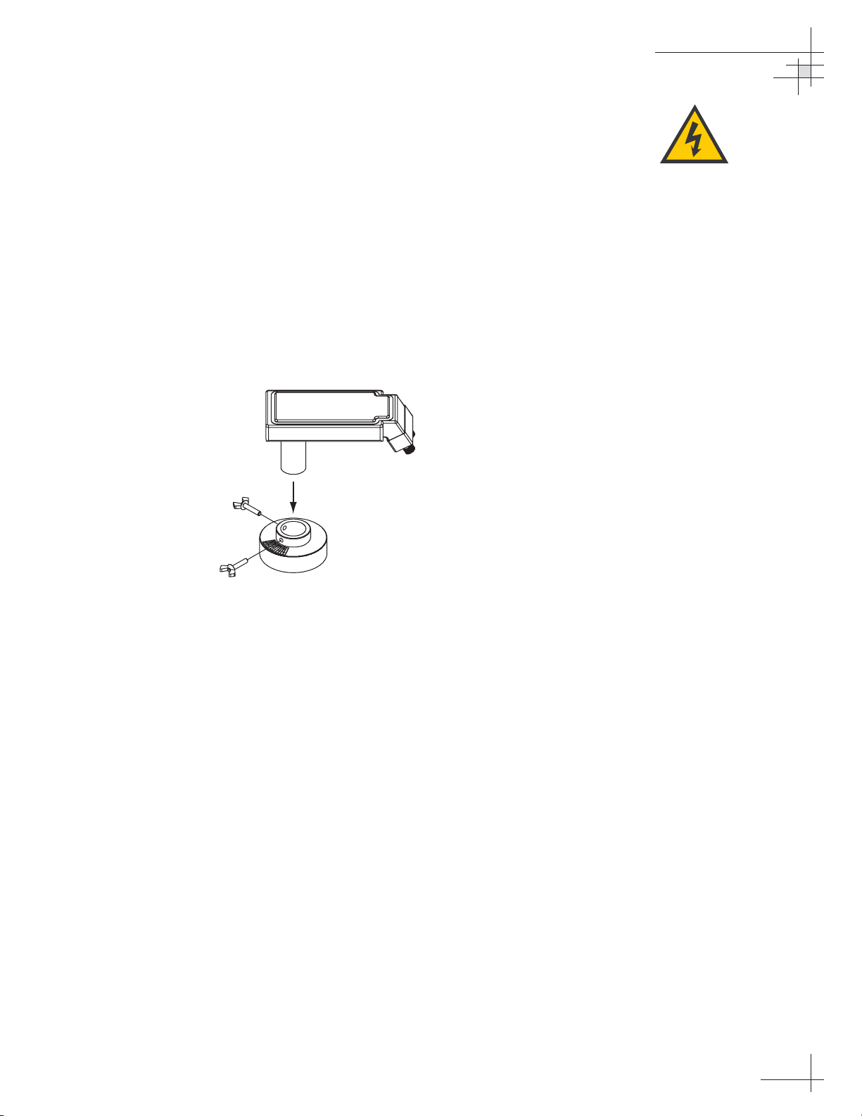
4.8 Replacing the LNB
The LNB assembly receives power from the IRD via the RF PCB.
Be certain that the IRD is turned off or disconnected from its
power source before removing or reconnecting the LNB.
Replacing a North American or Latin American LNB
1. Using a 7⁄16" wrench, carefully disconnect both RF
connectors from the LNB.
2. Loosen the two wing screws on the throat of the
choke feed until the LNB is free to slide out.
Withdraw the LNB as shown in Figure 4-10.
3. Insert the replacement LNB as far as it will go,
ensuring it reaches the bottom of the feedhorn. Be
careful not to puncture or dislodge the plastic seal
covering the LNB throat. Orient the LNB to align
with the strut holding the pair of RF cables.
4. Apply a small amount of thread-locking
compound (Loctite 425 or equivalent) to the wing
screw threads and tighten the screws to secure the
LNB in position.
5. Reattach the RF connectors to the LNB.
Maintenance
54-0166
65
Figure 4-10
North American or Latin American
LNB Replacement
Ensure that the IRD is turned off or
disconnected from its power source
before removing or reconnecting
the LNB.
Page 67
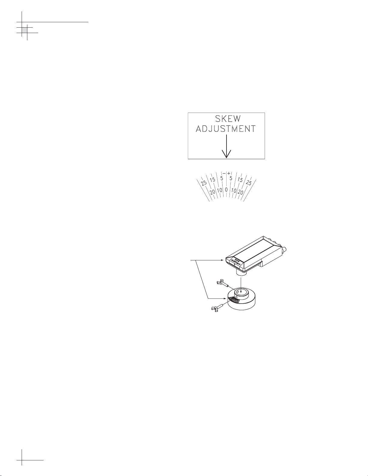
Replacing a European LNB
1. Using a 7⁄16" wrench, carefully disconnect the RF
connectors at the LNB.
2. Note the currently set skew value, as indicated by
the stickers on the LNB and choke assembly (see
Figure 4-11).
3. Loosen the wing screws and remove the LNB from
the choke assembly as shown in Figure 4-12.
4. Insert the replacement LNB as far as it will go,
ensuring it reaches the bottom of the feedhorn. Be
careful not to puncture or dislodge the plastic seal
covering the LNB throat. Adjust the LNB’s
position so that it has the same skew value noted
in Step 2.
5. Apply a small amount of thread-locking
compound (e.g., Loctite 425 or equivalent) to the
wing screw threads and tighten the screws to
secure the LNB in position.
6. Reattach the RF connectors to the LNB.
54-0166
66
TracVision 6 Technical Manual
Figure 4-12
European LNB Replacement
(Quad-output LNB Shown)
Figure 4-11
Skew Angle Labels
Skew Labels
Page 68
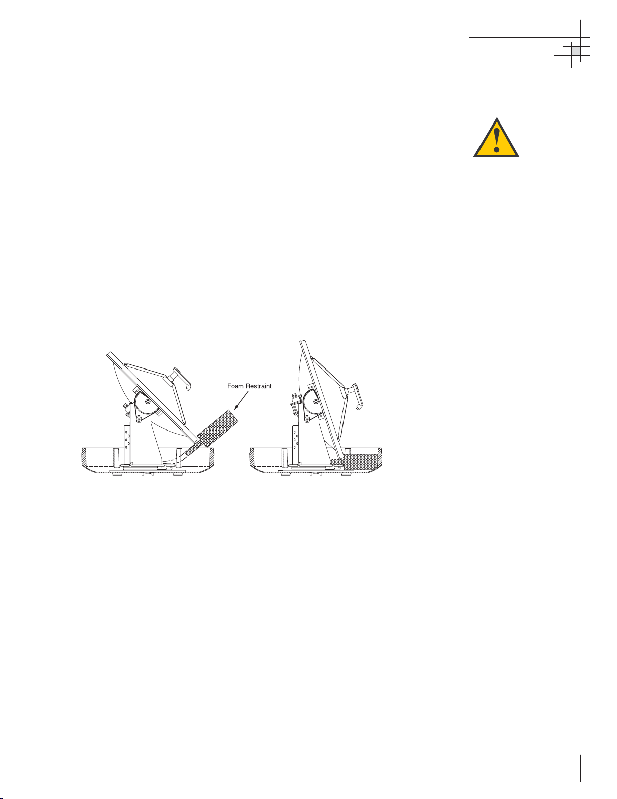
4.9 Preparing for Shipment
If you need to repack the antenna unit for shipment, the shipping
restraints removed during installation must be reinstalled. Follow
the steps below to reinstall the restraints.
1. Rotate the azimuth mechanism slowly to find the
limit switch stop. The front of the antenna should
be facing the forward arrow.
2. Rotate the azimuth mechanism 180˚ in the
opposite direction to ensure that the mechanism is
not resting on the limit switch stop.
3. With the antenna reflector slightly elevated, slip
the narrow end of the elevation shipping restraint
beneath the lip of the antenna reflector. Gently
wedge the restraint inside the baseplate as shown
in Figure 4-13.
Maintenance
54-0166
67
Figure 4-13
Elevation Shipping Restraint
Placement
When rotating the azimuth
mechanism by hand, go slowly!
Hitting the mechanical stops with
excessive force will damage the
azimuth limit switch.
Foam Restraint
Page 69
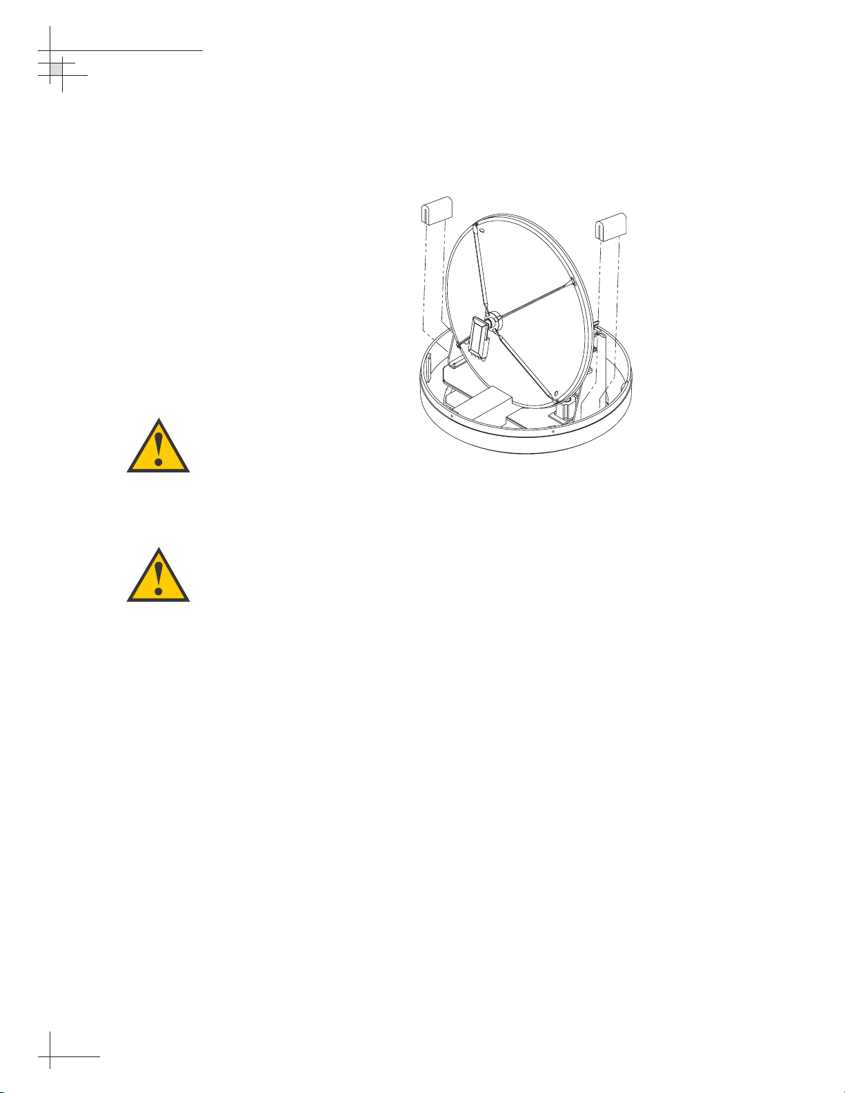
4. Insert the two azimuth shipping restraints
between the edge of the baseplate and the rotating
plate along the side of the antenna frame, as
pictured in Figure 4-14.
5. Pack the TracVision 6 antenna unit in its original
package.
6. As detailed in the warranty accompanying this
product and printed on the last page of this
manual, a Return Material Authorization (RMA)
number is required prior to the return of the
TracVision 6 system to KVH. Please contact the
KVH Technical Support Group at +1 401 847-3327
or via e-mail at techs@kvh.com to obtain an RMA
number. Please review your warranty to
familiarize yourself with all requirements,
liabilities, and policies.
54-0166
68
TracVision 6 Technical Manual
Figure 4-14
Azimuth Shipping Restraints
Placement
KVH is not liable for damage
caused by improper shipping.
Before returning the product, be
sure to obtain an RMA number
from KVH’s Technical Support
Department and write the
number on the outside of the
box. Shipments received without
an RMA number will be returned
to you at your expense.
Page 70

Appendices
54-0166
69
Appendices
This section contains several appendices of supplemental information,
including a mounting template, wiring diagram, and parser commands.
Contents
Appendix A System Specifications . . . . . . . . . . . . . . . . . . . . . . . . . . . . . . . . . .71
Appendix B Switchplate Template . . . . . . . . . . . . . . . . . . . . . . . . . . . . . . . . . . .73
Appendix C Comprehensive TracVision 6 System Wiring Diagram . . . . . . . . .75
Appendix D Startup Data Sequence . . . . . . . . . . . . . . . . . . . . . . . . . . . . . . . . .79
Appendix E Maintenance Port Parser Commands . . . . . . . . . . . . . . . . . . . . . .81
Page 71

System Specifications
54-0166
71
Appendix A
System Specifications
Physical Characteristics
Antenna Unit 27.4" (70 cm) h x 26.2" (67 cm) d;
55 lbs (25 kg)
Operating temperature –13° to +130° F (–25° to +55° C)
Storage temperature –40° to +185° F (–40° to +85° C)
Input Power
Input 11–16 VDC @ 3.5 amps nominal
(4.5 amps peak)
Antenna System Performance
Minimum EIRP 47 dBW
Elevation range 10° - 80°
Azimuth range 720°
Pitch/roll range ±15°
Pitch/roll rate 30°/second
Turn rate 45°/second
Yaw ±90° in 10 seconds
Tracking rate 30° per second
Position repeatability 0.1°
Surge/sway/heave ±0.2 G
Shock 20 G, 11 msec
Vibration 0.9 G rms over 5-33 Hz
Table A-1
TracVision 6 Antenna
Physical Specifications
Table A-2
TracVision 6 Power Specifications
Table A-3
TracVision 6 Performance
Specifications
Page 72
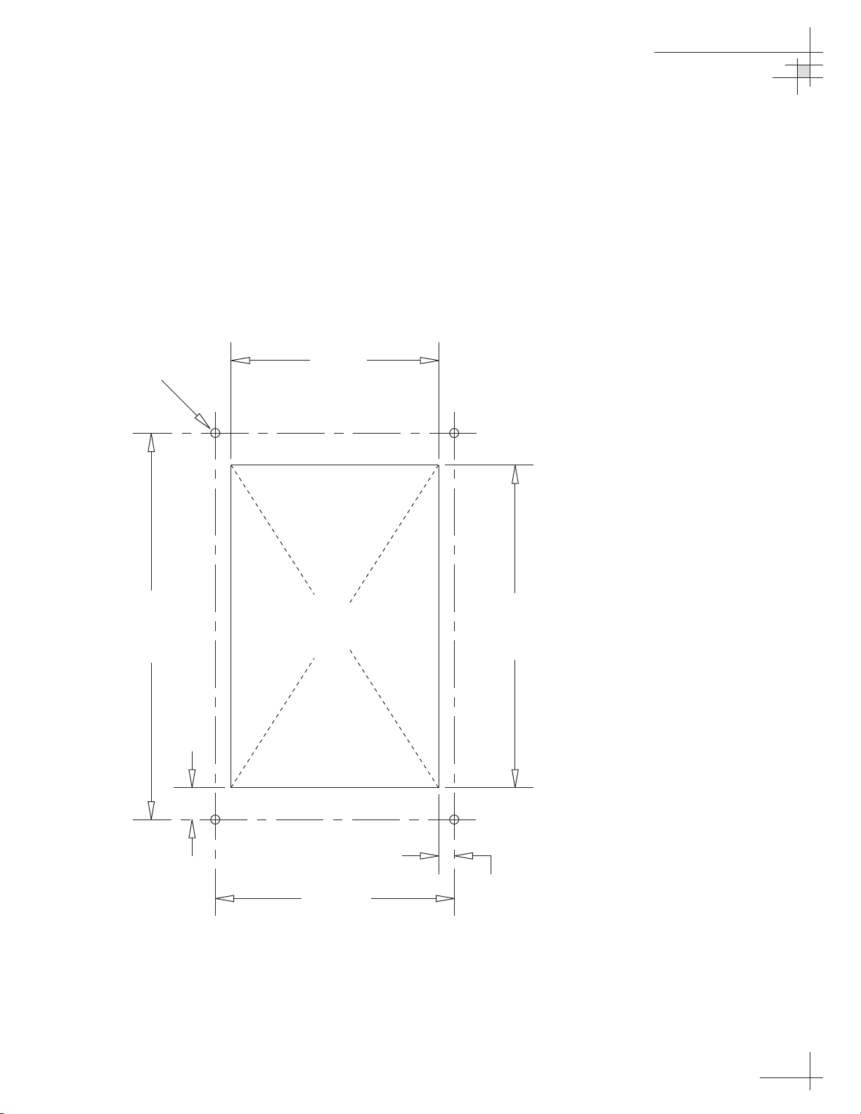
Appendix B
Switchplate Template
54-0166
Switchplate Template
73
/32" (3 mm) dia
3
3.82"
(97 mm)
.32" (8 mm)
2.05"
(52 mm)
3.19"
(81 mm)
Panel Cutout
2.36"
(60 mm)
.16" (4 mm)
Page 73

Appendix C
Comprehensive TracVision 6
Wiring Diagram
The comprehensive TracVision 6 wiring diagram is unavailable in PDF format. If
you require a copy of this wiring diagram, please contact KVH Technical
Support at +1 401 847-3327 or via email at techs@kvh.com. A copy of the diagram
can be mailed or faxed to you upon request.
Page 74

Startup Data Sequences
54-0166
79
Appendix D
Startup Data Sequence
The data on the following pages presents a sample startup
data sequence registered by the TracVision 6 when receiving
signals from DIRECTV, the DISH Network, or ExpressVu. This
sequence may vary based on the software version loaded onto
the TracVision 6 system. This data can be recorded using the
maintenance port and a PC.
?PGM
TracVision G6 Controller Rev X - Version X.XX - Serial number XXXXXXXX
EAD Motors
RF: ZAP
*** Initializing RF Controller ***
RF: S,A,V,U,V
RF: SATINSTALL,55,C,00,I
RF: L,A------------------------------------------ Identifies satellite A or B as currently RF:
SATCONFIG loaded for acquisition
RF: F,A,12368,20000,67,0X0000,V,U,2--------------Satellite configuration data, Satellite A
RF: F,A,12368,20000,67,0X0000,V,U,2
RF: F,A,12238,20000,67,0X0000,H,U,2
RF: F,A,12238,20000,67,0X0000,H,U,2
RF: F,B,00000,27500,34,0X0000,V,H,3--------------Satellite configuration data, Satellite B
RF: F,B,00000,27500,34,0X0000,V,L,3
RF: F,B,00000,27500,34,0X0000,H,H,3
RF: F,B,00000,27500,34,0X0000,H,L,3
RF: RF PCB Version X.X---------------------------Current RF software revision
RF COMM: PASS------------------------------------PASS is expected
Limit Switch Test
Limit Switch Status: PASS------------------------PASS is expected
*** Initializing Ext Sensor ***
RF: S,A,V,U,V
˛=h,0
˛S
˛=h,1
RF: S,A,H,U,V
RF: ?
ES Status Timeout
˛=h,0
˛S
˛=h,1
RF: S,A,V,U,V
ES Status Timeout
˛=h,0
˛S
˛=h,1
Page 75

54-0166
80
TracVision 6 Technical Manual
ES Status Timeout
Running Sensorless. No Ext Sensor Detected--------Configuring for sensorless operation
*** Initializing Antenna ***
*** NO GPS-Default Used ***-----------------------Accessing default location based on sat install
GPS: UTC: 083000.00, Lat: 4131.00N, Long: 7115.00W
*** Initializing Rate Bias ***
GPS: DSS_101 AZ = 220.9, EL = 33.4----------------Default satellite position based on sat install
RF: S,A,H,U,V
A/D: 2213 2067 497
A/D: 2058 2030 3132
A/D: 2037 2030 3118
A/D: 2040 2038 3089
RF: S,A,V,U,V
A/D: 2049 2046 2294
A/D: 2076 2085 2320
A/D: 2081 2075 2337
Gyro Bias: Az = 2060.52, El = 2058.07-------------Expected range is 1700-2300
Gyro Uncertainty: Az = 3.00, El = 3.00
RATE BIAS: PASS-----------------------------------PASS is expected
*** Entering Tracking ***
+POS: 62.7 34.0 2353
+POS: 63.1 33.6 2418
+POS: 63.1 33.6 2392
+POS: 63.0 33.5 2442
*** Network ID Check ***--------------------------Comparing the tracked satellite’s network ID to
+POS: 63.2 33.5 2472 the selected satellite’s network ID
+POS: 63.6 34.1 2454
+POS: 63.2 33.4 2492
RF: Y,0X0000---------------------------------------Indicates positive satellite identification
*** Tracking DSS_101 ***---------------------------Identifies satellite currently tracked
+POS: 63.9 33.8 2401 (TV broadcast image should be available)
+POS: 63.1 33.4 2505
+POS: 63.9 33.7 2425
+POS: 63.1 33.5 2562
+POS: 64.0 33.6 2427
Saved Sat Pos: AZ = 63.2, EL = 33.6
+POS: 63.1 33.7 2603
Page 76

Maintenance Port Parser Commands
54-0166
81
Appendix E
Maintenance Port
Parser Commands
The TracVision 6 system parser commands are parsed when the
system receives an ASCII carriage return (Hex 0D). An ASCII line
feed (Hex 0A) is permitted but is ignored in any transmitted
command. All system responses are terminated with an ASCII
carriage return followed by a line feed and ending with either an
acknowledge character (ASCII > (Hex 3E)) or a not-acknowledge
character (ASCII ? (Hex 3F)). The parser commands are shown
below in boldface capital letters but they are not case-sensitive. In
most cases, the command is responded to with an echo; that is, if
you type
ZAP, for example, and press “ENTER” the response
will be the command you have entered. For other commands, the
response is specific for each command, such as
VERSION,
STATUS or HELP.
E.1 System Commands
Software Version
Function: reports software version and system type
Command: VERSION
Response: KVH TracVision 6 Rev X - Version X.XX -
XXX Motors
System Status Report
Function: reports general system status
Command: STATUS
Response: system status string
Initialize/Restart the System
Function: initializes the system (performs a soft reset)
Command: ZAP
Response: echoes the command, then reinitializes the system
Table E-1
System Commands
Page 77

54-0166
82
TracVision 6 Technical Manual
Help on Parser Commands
Function: lists parser commands
Command: HELP
Response: lists all parser commands
Turn On Sleep Mode
Function: turns on Sleep Mode
Command: SLEEPON
Response: echoes the command
Turn Off Sleep Mode
Function: turns off Sleep Mode
Command: SLEEPOFF
Response: echoes the command
Turn On Instant On
Function: turns on Instant On feature
Command: INSTANTON
Response: echoes the command
Turn Off Instant On
Function: turns off Instant On feature
Command: INSTANTOFF
Response: echoes the command
Report Skew Angle
Function: reports skew angle of the current satellite
Command: SKEWANGLE
Response: SKEW ANGLE = XXXX.X
Report Serial Number
Function: reports system serial number
Command: =SERNUM
Response: SN = XXXXXXXX
Page 78
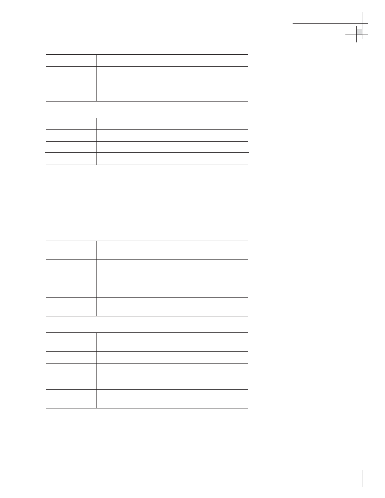
Maintenance Port Parser Commands
54-0166
83
Enter Serial Number
Function: enters system serial number
Command: =SERNUM,XXXXXXXX
Where: XXXXXXXX = the system’s serial number
Response: SN = XXXXXXXX
Configure System
Function: configures software for a particular system model
Command: =TVXXXX
Where: XXXX = system model (i.e., G6HP)
Response: system configures software and antenna restarts
E.2 Manual Positioning Commands
To execute the following commands, first put the antenna unit in
idle mode by typing
HALT and pressing “ENTER.” Positioning
commands may be entered after the antenna comes to rest.
Azimuth Angle
Function: commands a manual azimuth angle that the
mechanism moves to
Command: AZ,XXXX (range is 0000-3599)
Argument: desired azimuth angle of the mechanism relative to
external magnetic reference, or baseplate fwd,
000°-359.9°
Response: echoes the command; mechanism moves at a
fixed velocity
Elevation Angle
Function: commands a manual elevation angle that the
mechanism moves to
Command: EL,XXX (range is 100-850)
Argument: desired elevation angle of the mechanism relative to
up, or external sensor attitude reference, 10.0°-
85.0°
Response: echoes the command; mechanism moves at a
fixed velocity
Table E-2
Manual Positioning Commands
Page 79
54-0166
84
TracVision 6 Technical Manual
Azimuth CW Step
Function: commands a manual 0.1° clockwise step in azimuth
angle
Command: 6
Response: echoes the command
Azimuth CCW Step
Function: commands a manual 0.1° counter-clockwise step in
azimuth angle
Command: 4
Response: echoes the command
Elevation UP Step
Function: commands a manual 0.1° UP step in elevation
angle
Command: 8
Response: echoes the command
Elevation DOWN Step
Function: commands a manual 0.1° DOWN step in elevation
angle
Command: 2
Response: echoes the command
E.3 Operational Commands
Tracking Mode
Function: starts active tracking of the satellite
Command: TRACK
Response: echoes the command
Idle Mode
Function: halts active tracking and conical scan, then enters
Idle mode
Command: HALT
Response: echoes the command
Table E-3
Operational Commands
Page 80

Maintenance Port Parser Commands
54-0166
85
E.4 Tracking and Conical
Scan Commands
Target Location
Function: reports the target location in antenna frame; data
format is E### for elevation in degrees 000-900 and
A#### for azimuth in degrees 0000-3599 with
implied decimals
Command: TGTLOCATION
Response: Target Location = A = E###, A####
B = E###, A####
Analog Signal Strength Report
Function: reports signal strength from RF detector circuit in
A/D counts (000-FFF Hex)
Command: SIGLEVEL
Response: Signal Strength = XXXX
E.5 RF Board Commands
Serial Communications, Status/Polarization Report, Tone Changes
Function: starts serial communications, reports status and
polarization/tone changes
Command: @S
Response: S,s,p,b,m <cr> every 5 seconds until ><cr>is
returned from system software
Where: s = satellite (A = primary, B = secondary)
p = polarization (V = vertical, H = horizontal,
R = right, L = left, X = no LNB power)
b = band (H = high band, L = low band,
G = Latin America, U = USA)
m = mode (V = valid, I = invalid)*
* The Mode bit is used to evaluate the Satellite, Polarization and Band
combination vs. the Frequency/Symbol Rate/FEC currently in RAM. This
bit will be set to invalid if the Frequency for the selected combination is
set to 0x0000; otherwise it will be set to valid. For example the Mode bit
will be set to invalid when the frequency is set to 00000 to indicate that
there is not a frequency to track for the LNB tone and voltage setting.
Table E-4
Tracking and Conical
Scan Commands
Table E-5
RF Board Commands
Page 81
54-0166
86
TracVision 6 Technical Manual
Report RF Tracking Parameters
Function: reports all RF tracking parameters for primary &
secondary satellites*
Command: @SATCONFIG
Response: F,x,fffff,S,C,ID,P,B,D <cr>
Where: x = satellite (A = primary, B = secondary)
fffff = frequency in MHz (00000 and 10700 to
12700)
S = symbol rate in Mbit/Sec (1000 to 29999)
C = FEC code rate (valid rates = 12, 23, 34, 56,
67, 78)
ID = satellite network ID in hexidecimal format
(valid range = 0x0000 to 0xffff hex)
P = LNB polarization (V = vertical, H = horizontal,
R = right, L = left)
B = LNB down conversion frequency (L = low,
H = high, G = Latin America, U = USA)
D = decoding type (0 = test, 1 = DSS-A,
2 = DSS-B, 3 = DVB)
* This command returns all eight combinations of the Satellite/Freq/Sym/
FEC/ID/POL/Band/Decode currently stored in RAM.
Page 82
Maintenance Port Parser Commands
54-0166
87
Set RF Tracking Parameters
Function: sets RF tracking parameter
Command: @SATCONFIG,X,N,F,S,C,ID,P,B,D<cr>
Response: Echoes the input data
Where: @SATCONFIG = directs data to the RF Board
X = satellite location A or B
N = satellite table # (98 & 99 are slots for user-
configured satellites)
F = frequency in MHz (either 00000 or a range from
10700 - 12700)
S = satellite transponder symbol rate in
Mbit/second (01000 - 29999)
C = FEC code (e.g., 12, 23, 34, 56, 67, 78)
ID = satellite network ID in hexidecimal format
(0x####)
P = LNB polarization (V = vertical,
H = horizontal, R = right, L = left)
B = LNB down conversion frequency (L = low,
H = high, G = Latin America, U = USA)
D = decoding type (0 = test, 1 = DSS-A,
2 = DSS-B, 3 = DVB)
Switch Satellites
Function: shifts tracking to the second satellite
Command: @L,A or B
Response: echoes the command
Where: A = switches to Satellite A
or
B = switches to Satellite B
ID Match/Decoded Network ID
Function: reports ID match and decoded network ID
Command: @CHECKID
Response: Y,0X####
N,0X####
Y,NoID
N,NoID
Where: Y = yes
N = no
0X#### = network ID
NoID = satellite unidentified
Page 83
54-0166
88
TracVision 6 Technical Manual
Frequency Scan
Function: updates satellite frequency data
Command: @SC,XXXXX,YY
Where: XXXXX = symbol rate (010000 - 399999)
YY = FEC code (e.g., 12, 23, 34, 56, 67, 78)
Response: system automatically searches for the frequency
with the strongest signal, then updates the
satellite’s programmed data with the new frequency
(and associated network ID) and stores it in the
satellite library
RF PCB Software Version
Function: reports RF PCB software version
Command: @VER
Response: RF PCB Version X.X
Report Tracking Information
Function: reports hardware/software locks, AGC value, bit
error rate, and ADC value
Command: @I
Response: I,X,G,B,D,Y
Where: X = hardware lock (0 = not locked, 1 = locked on
satellite)
G = AGC value (signal level)
B = bit error rate
D = ADC value
Y = software lock (0 = not locked, 1 = locked on
satellite)
Do NOT use the Frequency Scan
function unless directed by KVH
Technical Support or a KVHauthorized technician. Improper
data selection may affect the
system’s operation.
Page 84
Maintenance Port Parser Commands
54-0166
89
E.6 Installation Commands
Set/Report GPS Position
Function: reports or sets default GPS position
Command: GPS<cr>
GPS,XX,D,YYY,E
Response: GPS = XXD YYYE
GPS: XXD YYYE
Where: XX = latitude (0-90)
D = S (South) or N (North)
YYY = longitude (0-180)
E = E (East) or W (West)
Report Satellite Names
Function: reports names for satellites A and B
Command: SATINSTALL
Response: SATINSTALL,<sat_a_name>,<sat_b_name>
Report Tracked Satellite
Function: reports name of satellite currently being tracked
Command: SAT
Response: SAT = <sat_name>
Report Configured Satellite Names
Function: reports names for all configured satellites
Command: SATLISTA
Response: SATLISTA,<sat_name1>,...,<sat_nameX>
Report Valid Satellite B Selections
Function: reports names for all valid Satellite B selections for
a given Satellite A selection
Command: SATLISTB,<sat_a_name>
Response: SATLISTB,<sat_a_name>,<sat_b_name1>
...,<sat_b_nameX>
Install Satellite Pair
Function: installs satellites A and B as the satellite pair
Command: SATINSTALL,<sat_a_name>,<sat_b_name>
Response: If valid pair, echoes the input data
If invalid pair, returns error message
Table E-6
Installation Commands
Page 85
54-0166
90
TracVision 6 Technical Manual
Configure Longitude of a User-configurable Satellite
Function: configures one of the user-configurable satellites
with the longitude provided
Command: SATCONFIG,USERX,YYY,Z,D,L
Response: If valid, echoes the input data
If invalid, returns error message
Where: X = 1 or 2
YYY = longitude (0-180)
Z = E (East) or W (West)
D = decoding type (0 = test, 1 = DSS-A,
2 = DSS-B, 3 = DVB)
L = LNB polarization (C = circular, L = linear)
Set Saved Satellite Position
Function: sets saved satellite position
Command: GOTO,AZXXXX,ELYYY
Response: SAVED SAT POS: AZ = XXXX, EL = YYY
Where: XXXX = azimuth (0000 - 3599)
YYY = elevation (100 - 850)
E.7 Debug Commands
Enter Debug Mode
Function: enters Debug mode
Command: DEBUGON
Response: echoes the command, system enters Debug mode
Limit Switch Test
Function: performs a limit switch test
Command: =LSTEST
Response: Limit Switch Status: PASS
Set/Report Offset Angles
Function: reports or sets system offset angles
Command: OFFSETS
OFFSETS,XXXXX,YYYY
Response: Offsets = XXXXX.X YYYYY.Y
Where: X = azimuth offset (-1800 - 1800)
Y = elevation offset (-450 - 450)
Table E-7
Debug Commands
Page 86
Maintenance Port Parser Commands
54-0166
91
Apply Default Values to Default Satellites
Function: updates the default satellites to the default values
Command: SATPAIR,X
Response: displays numerous frequency commands and
reports “Satellite Installation Complete”
Where: X = 0 (satellites default to Astra1 & Hotbird)
or
X = 1 (satellites default to Expressvu and
EchoStar 119)
or
X = 2 (satellites default to DSS_101 and
DSS_119)
or
X = 3 (satellites default to Galaxy3CN and
None)
Report Last Satellite Tracked/Update Value
Function: reports the last satellite tracked or updates the last
tracked satellite to the value input if it is different
from the current value
Command: LASTSAT
LASTSAT,X
Response: Last = <sat_name>
Where: X = A (updates to Satellite A)
or
X = B (updates to Satellite B)
Page 87

KVH Industries Limited Warranty
TracVision 6
Limited Warranty on Hardware
KVH Industries, Inc. warrants the KVH product purchased against defects in materials for a period of TWO (2) years
and against factory labor costs for a period of ONE (1) year from the date of original retail purchase by the original
purchaser. It is the customer’s responsibility to verify the date of purchase by returning the warranty card included with
the product to KVH within 30 days of purchase, or by providing a copy of a dated sales receipt for the KVH product
under warranty with the warranty claim. If this date cannot be verified, the warranty period will begin 30 days after the
date of manufacture of the original product purchased.
If you discover a defect, KVH will, at its option, repair, replace or refund the purchase price of the product at no charge
to you, provided you return it during the warranty period, transportation charges prepaid, to the factory direct. Please
attach your name, address, telephone number, a description of the problem and a copy of the bill of sale or sales
receipt as proof of date of original retail purchase, to each product returned to warranty service. Alternatively, you may
bring the product to an Authorized KVH dealer/distributor for repair. During the first year, and if the product was
installed by an Authorized KVH dealer/distributor (identified with the KVH Authorized dealer/distributor list), KVH will
cover the dealer’s/distributor’s labor charges for warranty repairs, provided the dealer/distributor contacts KVH for preapproval of the charges. Approval of charges is at KVH’s sole discretion.
This Limited Warranty does not apply if the product has been damaged by accident, abuse, misuse or misapplication
or has been modified without the written permission of KVH; if any KVH serial number has been removed or defaced;
or if any factory-sealed part of the system has been opened without authorization.
Return Authorization
A Return Material Authorization is required prior to returning the product to KVH Industries. Please call our Technical
Support Department at +1 401 847-3327 or send an e-mail to techs@kvh.com to obtain the RMA number. Write the
number in large, clear characters on the outside of the box. To avoid confusion and misunderstandings, shipments
without an RMA number clearly visible on the outside box will be refused and returned to you at your expense. If
possible, use the original box and packing material to protect the equipment from damage in shipment. KVH assumes
no responsibility for warranty shipments from the customer to the factory if not shipped in the manner prescribed
above.
THE EXPRESS WARRANTIES SET FORTH ABOVE ARE THE ONLY WARRANTIES GIVEN BY KVH WITH
RESPECT TO ANY PRODUCT FURNISHED HEREUNDER; KVH MAKES NO OTHER WARRANTIES, EXPRESS,
IMPLIED OR ARISING BY CUSTOM OR TRADE USAGE, AND SPECIFICALLY DISCLAIMS ANY WARRANTY OF
MERCHANTABILITY OR OF FITNESS FOR A PARTICULAR PURPOSE. SAID EXPRESS WARRANTIES SHALL
NOT BE ENLARGED OR OTHERWISE AFFECTED BY TECHNICAL OR OTHER ADVICE OR SERVICE PROVIDED
BY KVH IN CONNECTION WITH ANY PRODUCT.
KVH's liability in contract, tort or otherwise arising out of or in connection with any product shall not exceed the price
paid for the product. IN NO EVENT SHALL KVH BE LIABLE FOR SPECIAL, PUNITIVE, INCIDENTAL, TORT OR
CONSEQUENTIAL DAMAGES OR LOST PROFITS OR GOODWILL (INCLUDING ANY DAMAGES RESULTING
FROM LOSS OF USE, DELAY IN DELIVERY OR OTHERWISE) ARISING OUT OF OR IN CONNECTION WITH THE
PERFORMANCE OR USE OR POSSESSION OF ANY PRODUCT, OR ANY OTHER OBLIGATIONS RELATING TO
THE PRODUCT, EVEN IF KVH HAS BEEN ADVISED OF THE POSSIBILITY OF SUCH DAMAGES.
If any implied warranty, including implied warranties of merchantability and fitness for a particular purpose, cannot be
excluded under applicable law, then such implied warranty shall be limited in duration to ONE (1) YEAR from the date
of the original retail purchase of this product by the original purchaser.
Some states/countries do not allow the exclusion or limitation of implied warranties or liability for incidental or
consequential damages, so the above limitations may not apply to you. This warranty gives you specific legal rights,
and you may also have other rights which vary from state/country to state/country.
Page 88

KVH Industries, Inc.
50 Enterprise Center Middletown, RI 02842-5279 U.S.A.
Phone: (401) 847-3327 Fax: (401) 849-0045
E-mail: info@kvh.com Internet: www.kvh.com
KVH Europe A/S
Kokkedal Industripark 2B 2980 Kokkedal Denmark
Phone: +45 45 160 180 Fax: +45 45 160 181
E-mail: info@kvh.dk Internet: www.kvh.com
KVH®and TracVision®are registered trademarks of KVH Industries, Inc.
TV6_TM_Cover.0604
®
 Loading...