

Page 1

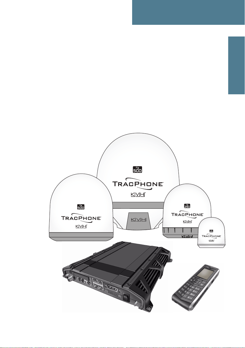
TracPhone FleetBroadband
FB250 & FB500
TracPhone FB250 & FB500 User’s Guide
Page 2
TracPhone FB250 & FB500
User’s Guide
The KVH® Industries’ TracPhone® FB250/FB500 system, manufactured by
Thrane & Thrane, delivers high-speed data and voice communications via
satellite through Inmarsat’s Broadband Global Area Network (BGAN). This
user’s guide provides all of the information you need to operate, set up, and
troubleshoot the system. For detailed installation information, please refer to
the Installation Guide.
Product Information
Before installing the TracPhone,
write down the following numbers:
SIM card #
Antenna serial #
Terminal serial #
Please direct technical questions to:
North/South America, Australia: Europe, Middle East, Asia:
KVH Industries, Inc. KVH Europe A/S
50 Enterprise Center Kokkedal Industripark 2B
Middletown, RI 02842-5279 USA 2980 Kokkedal, Denmark
Tel: +1 401 847-3327 Tel: +45 45 160 180
Fax: +1 401 845-8133 Fax: +45 45 160 181
E-mail: techs@kvh.com E-mail: support@kvh.dk
Internet: www.kvh.com Internet: www.kvh.com
If you have any comments regarding this manual, please e-mail them to
manuals@kvh.com. Your input is greatly appreciated!
KVH Part # 34-125645-D
© 2008, KVH Industries, Inc., All rights reserved.
Page 3

Trademark Information
TracPhone, KVH, and the unique light-colored dome with contrasting
baseplate are registered trademarks of KVH Industries.
Thrane & Thrane is a registered trademark of Thrane & Thrane A/S in the
European Union and the United States.
Windows and Outlook are registered trademarks of Microsoft Corporation in
the United States and other countries.
Inmarsat is a registered trademark of International Maritime Satellite
Organisation (IMSO) and is licensed by IMSO to Inmarsat Limited and
Inmarsat Ventures plc.
Inmarsat’s product names are trademarks or registered trademarks of
Inmarsat.
All other trademarks are the property of their respective owners.
Disclaimer
Every effort has been made to ensure the correctness and completeness of the
material in this document. No company shall be liable for errors contained
herein. The information in this document is subject to change without notice.
No warranty of any kind is made with regard to this material, including, but
not limited to, the implied warranties of merchantability and fitness for a
particular purpose.
Page 4
Safety summary 1
The following general safety precautions must be observed during all
phases of operation, service and repair of this equipment. Failure to comply
with these precautions or with specific warnings elsewhere in this manual
violates safety standards of design, manufacture and intended use of the
equipment. KVH Industries assumes no liability for the customer's failure to
comply with these requirements.
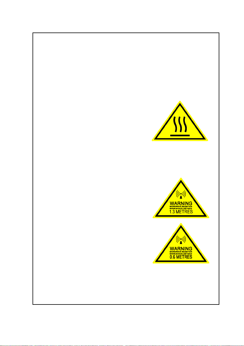
Observe marked areas
Under extreme heat conditions do not touch
areas of the terminal or antenna that are
marked with this symbol, as it may result in
injury.
Microwave radiation hazards
During transmission the antenna in this system radiates Microwave
Power.This radiation may be hazardous to humans close to the antenna.
During transmission, make sure that nobody gets closer than the
recommended minimum safety distance.
On the TracPhone FB500, the minimum safety
distance to the antenna panel on the focal line
is 1.3 m, based on a radiation level of 10 W/m2.
The radiation level is 100 W/m2 at a distance of
0.4 m from the antenna panel. Refer to the
drawing on the next page.
On the TracPhone FB250, the minimum safety
distance to the antenna panel on the focal line
is 0.6 m, based on a radiation level of 10 W/m2.
The radiation level is 100 W/m2 at a distance of
0.2 m from the antenna panel. Refer to the
drawing on the next page.
iii
Page 5
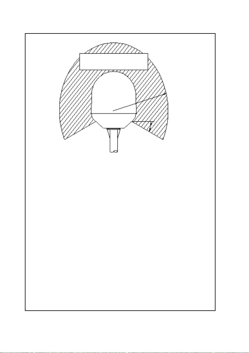
MICROWAVE RADIATION
No personnel within safety distance
Safety distance:
FB500:
1.3 m, 10 W/m
(0.4 m, 100 W/m
FB250:
0.6 m, 10 W/m
(0.2 m, 100 W/m
25° for FB500
60° for FB250
2
2
2
2
Distance to other equipment
Do not move the antenna closer to radars than the minimum safe distance
specified in the installation manual - it may cause damage to the antenna.
The equipment must be installed with the following minimum safe distances
to magnetic steering compass:
TracPhone terminal: min. 0.3 m.
TracPhone FB500 antenna: min. 1.0 m
TracPhone FB250 antenna: min. 1.1 m
Service
User access to the interior of the terminal is prohibited. Only a technician
authorized by KVH Industries may perform service - failure to comply with
this rule will void the warranty. Access to the interior of the antenna is
allowed, but only for replacement of certain modules - as described in the
Installation manual. General service may only be performed by a technician
authorized by KVH Industries.
)
)
Do not service or adjust alone
Do not attempt internal service or adjustments unless another person,
capable of rendering first aid resuscitation, is present.
iv
Page 6

Grounding, cables and connections
To minimize shock hazard, the equipment chassis and cabinet must be
connected to an electrical ground. Both terminal and antenna must be
grounded to the vehicle. For further grounding information refer to the
Installation manual.
Do not extend the cables beyond the lengths specified for the equipment.
The cable between the terminal and antenna can be extended if it complies
with the specified data concerning cable losses etc.
All cables for the TracPhone system are shielded and should not be affected
by magnetic fields. However, try to avoid running cables parallel to AC
wiring as it might cause malfunction of the equipment.
Power supply
The voltage range is 10.5 - 32 V DC; 14 A - 5.5 A. It is recommended that the
voltage is provided by the 24 V DC bus on the ship. Be aware of high start-up
peak current: 20 A@24 V, 5 ms.
If a 24 V DC power bus is not available, an external 115/230 VAC to 24 V DC
power supply can be used.
Do not operate in an explosive atmosphere
Do not operate the equipment in the presence of flammable gases or fumes.
Operation of any electrical equipment in such an environment constitutes a
definite safety hazard.
Keep away from live circuits
Operating personnel must not remove equipment covers. Component
replacement and internal adjustment must be made by qualified
maintenance personnel. Do not replace components with the power cable
connected. Under certain conditions, dangerous voltages may exist even
with the power cable removed. To avoid injuries, always disconnect power
and discharge circuits before touching them.
Failure to comply with the rules above will void the warranty!
v
Page 7

About the manual 2
Intended readers
This manual is a user manual for the TracPhone FB500 system and
the TracPhone FB250 system. The readers of the manual include
anyone who is using or intends to use one of these two systems.
No specific skills are required to operate the TracPhone system.
However, it is important that you observe all safety requirements
listed in the beginning of this manual, and operate the system
according to the guidelines in this manual.
Manual overview
Note that this manual does not cover installation nor does it cover
how to use the IP handset that comes with the system. For
information on installation refer to the installation manual and for
information on the IP handset refer to the user manual for the IP
handset. Part numbers for both manuals are listed in the next
section.
This manual has the following chapters:
• Introduction contains an overview of the BGAN services and a
brief description of the system.
• Getting started explains how to insert SIM card and start up
the unit. It also contains a short guide to making the first call.
• Operating the system explains how to use the system.
• Using the web interface explains how to use the built-in web
interface of the terminal, and describes the available menus
and settings, including advanced setup of interfaces.
• Troubleshooting contains a short troubleshooting guide and
explains how to update software. It also describes the
functions of the light indicators and the Reset button, and
explains the event messages that may show in the web
interface. Further, it gives information on where to get help if
needed.
vi
Page 8
This manual may not always reflect the latest software
functionality of your terminal. To obtain the latest version of the
manual, please visit www.kvh.com and download the latest
version from the FB250 or FB500 product page.
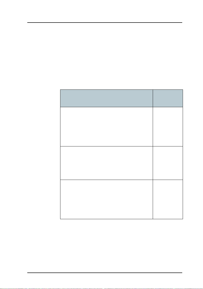
Related documents
The below list shows the documents related to this manual and to
the TracPhone FB500 and TracPhone FB250 system.
Title and description
TracPhone FB250 & FB500
Installation Guide
Explains how to install the TracPhone terminal,
the TracPhone FB500 antenna and the
TracPhone FB250 antenna.
TracPhone FB250 & FB500
Quick Reference Guide
A short guide to the most important functions
of the TracPhone systems.
TracPhone IP Handset User’s Guide
Explains the features and functions of the IP
handset. The IP handset works as a standard IP
handset, but also serves as a user interface for
the TracPhone systems.
Document
number
34-125646
54-0554
34-126059
vii
Page 9

Typography
In this manual, typography is used as indicated below:
Bold is used for the following purposes:
• To emphasize words.
Example: “Do not touch the antenna”.
• To indicate what the user should select in the user interface.
Example: “Select SETTINGS > LAN”.
Italic is used to emphasize the paragraph title in cross-references.
Example: “For further information, see Connecting Cables on
page...”.
viii
Page 10

Table of Contents
Safety summary ................................................................iii
About the manual ..............................................................vi
Chapter 1 Introduction
Welcome ............................................................................ 1
In this chapter ....................................................................2
Features and interfaces ......................................................3
Main units ..........................................................................4
The Inmarsat BGAN system ............................................... 11
Matrix of services and interfaces .......................................17
What’s next? .................................................................... 18
Chapter 2 Getting started
In this chapter ...................................................................19
Before you start .................................................................19
Starting up the terminal ....................................................21
Connecting the IP handset ...............................................24
Connecting a computer ....................................................25
Entering the SIM PIN for the terminal ...............................26
Registering on the BGAN network ....................................30
Making the first call .........................................................32
What’s next? ....................................................................33
Chapter 3 Operating the system
In this chapter ..................................................................35
ix
Page 11

Table of Contents
General ............................................................................35
Using a phone or fax machine ..........................................38
Using a computer .............................................................52
Using the IP handset ........................................................55
What’s next? .....................................................................55
Chapter 4 Using the web interface
In this chapter ..................................................................57
Introduction .....................................................................57
Entering the SIM PIN in the web interface ........................63
Using the Dashboard ........................................................65
Using the phone book ...................................................... 71
Using the Call log .............................................................76
Handling SMS messages ..................................................79
Setting up the interfaces .................................................. 86
Managing LAN network users ...........................................111
Uploading software ........................................................ 126
Selecting the preferred BGAN satellite ............................. 131
Administration ................................................................ 133
Help desk and diagnostic report ..................................... 148
Event logging and self test .............................................. 150
What’s next? ................................................................... 152
Chapter 5 Troubleshooting
In this chapter ................................................................ 153
Getting support .............................................................. 153
x
Page 12

Table of Contents
Uploading software .........................................................154
Part numbers ..................................................................155
Troubleshooting guide ....................................................157
Status signaling ..............................................................163
Logging of events ............................................................179
Reset button ................................................................... 180
Chapter 6 Conformity
TracPhone FB500 ............................................................183
TracPhone FB250 ............................................................185
Glossary ........................................................................................187
Index ........................................................................................193
xi
Page 13

Table of Contents
xii
Page 14
Chapter 1
Introduction 1
Welcome
Congratulations on the purchase of your TracPhone system!
TracPhone FB500 and TracPhone FB250 are maritime broadband systems,
providing simultaneous high-speed data and voice communication via
satellite through the Broadband Global Area Network (BGAN).
Introduction
1
Page 15

Chapter 1: Introduction
Applications include:
• Internet browsing
•E-mail
• Phone and fax services
• Large file transfers
• Video conferencing and Streaming
• VPN (Virtual Private Network) access to corporate servers
In this chapter
This chapter introduces the TracPhone FB500 system and the
TracPhone FB250 system, and gives an overview of the physical units and
their features and functions.
It also gives an overview of the BGAN system and services.
2 In this chapter
Page 16

Features and interfaces
The TracPhone system offers the following features and interfaces:
Chapter 1: Introduction
Simultaneous voice and data communication over BGAN
Full duplex, single or multi-user, up to:
TracPhone FB500: 432 kbps
TracPhone FB250: 284 kbps
Support for streaming IP at:
TracPhone FB500: 32, 64, 128, 256 kbps
TracPhone FB250: 32, 64, 128 kbps
ISDN service, only TracPhone FB500: 64 kbps
Voice: Standard Voice (4.0 kbps) or 3.1 kHz Audio
4 LAN (Local Area Network) ports with Power over Ethernet (PoE) for
computers, e-hubs, IP handsets etc.
2 Standard Phone/Fax ports for standard phones, fax machines or analog
modems
1 Euro ISDN port for ISDN phones or, for TracPhone FB500 only: G4 fax or
ISDN modem
1 L-Band output for connecting a broadcast receiver for maritime data
1 multi-purpose I/O connector with 5 configurable inputs/outputs
1 SIM slot for your BGAN SIM card
Integral DHCP/NAT router
Introduction
Built-in web interface allowing you to manage your phone book,
messages and calls, and customize the terminal to your specific needs
Input power: 10.5 - 32 V DC (14 A - 5.5 A)
CE certified
Features and interfaces 3
Page 17

Chapter 1: Introduction
Main units
TracPhone FB500/ TracPhone FB250
The main difference between the TracPhone FB500 system and the
TracPhone FB250 system lies in the antenna.
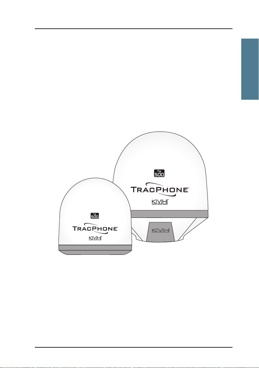
• TracPhone FB500 uses an FB500 antenna, which is a maritime BGAN Class
8 antenna.
This antenna is larger and provides more bandwidth than the antenna
used for the TracPhone FB250 system.
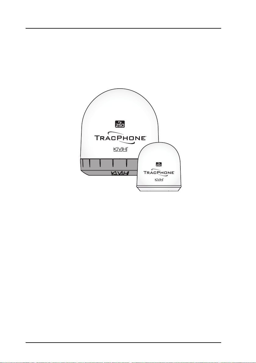
• TracPhone FB250 uses an FB250 antenna, which is a medium size,
maritime BGAN Class 9 antenna.
The TracPhone FB500 system and the TracPhone FB250 system basically use
the same type of terminal, except that the TracPhone FB500 offers a few more
features than the TracPhone FB250. See Features and interfaces on page 3.
Units overview
The TracPhone FB500 system includes the following main units:
• TracPhone FB500 antenna
• TracPhone terminal
• TracPhone FleetBroadband IP handset with cradle
The TracPhone FB250 system includes the following main units:
• TracPhone FB250 antenna
• TracPhone terminal
• TracPhone FleetBroadband IP handset with cradle
4Main units
Page 18
TracPhone antennas
TracPhone FB500 antenna
Chapter 1: Introduction
The TracPhone FB500 system uses the FB500 antenna, which is a maritime
BGAN antenna. The antenna contains all functions for satellite tracking,
including a GPS system. A single coaxial cable carries all RF communication,
supply voltage and modem communication between the antenna and the
terminal.
For information on how to install the antenna, refer to the installation manual.
Introduction
This antenna is larger and provides more bandwidth than the antenna used
for the TracPhone FB250 system.
Main units 5
Page 19
Chapter 1: Introduction
TracPhone FB250 antenna
The TracPhone FB250 system uses the FB250 antenna, which is a medium
size, maritime BGAN phased array antenna.
For information on how to install the antenna, refer to the installation manual.
6Main units
Page 20
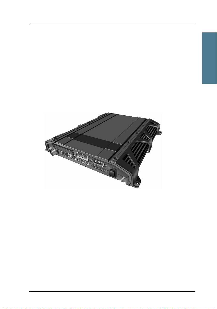
TracPhone terminal
Overview
Chapter 1: Introduction
Whether you have purchased a TracPhone FB500 system or a
TracPhone FB250 system, the terminal is basically the same. For this reason
this section covers both systems.
The TracPhone terminal is the controlling unit in the TracPhone system. It
contains all user interfaces and LED indicators and stores configuration data.
For information on how to install the terminal, refer to the installation manual.
Tools for setup and daily use
The IP handset can be used for displaying status and for entering the PIN code
for the terminal. The IP handset connects to the LAN interface of the terminal.
For information on how to use the handset menus, see the user manual for the
IP handset.
Introduction
The built-in web interface is used for easy configuration and daily use. The
web interface is accessed from a computer connected to the terminal, using an
Internet browser. No installation of software is needed.
For further information on the web interface, see Chapter 4, Using the web
interface.
Main units 7
Page 21

Chapter 1: Introduction
SIM card
The terminal has a SIM slot (Subscriber Identity Module) located in the
connector panel behind a small cover plate.
The terminal requires a dedicated FleetBroadband SIM card, which is acquired
from your Airtime Provider.
The system requires a SIM card to go online and to access the settings of the
terminal. However, using the web interface you can view the Dashboard and
upload software without inserting a SIM card. Upload of software without a
SIM card requires an Administrator user name and password.
8Main units
Page 22
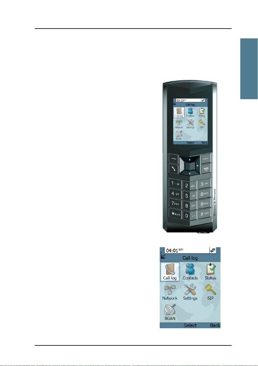
IP handset and cradle
IP handset
The IP handset communicates using Internet
protocols. The handset is not strictly
dedicated to the TracPhone system, but can
also be used in a public network as a
standard IP telephone.
When the IP handset is used with the
terminal, it communicates using Internet
protocol between the handset and the
terminal. However, on the BGAN network
side of the terminal, calls are transmitted as
circuit switched calls.
The IP handset is powered directly from the
LAN interface using Power over Ethernet
(PoE).
Chapter 1: Introduction
Introduction
When connected to the terminal the IP
handset provides a dedicated BGAN menu
with a subset of the terminal configuration
options.
For more information on the functions of the
IP handset, refer to the user manual for the
IP handset.
Main units 9
Page 23

Chapter 1: Introduction
IP cradle
The IP cradle serves as a holder for the IP handset.
The cradle connects to the coil cord from the handset and, using an Ethernet
cable, to the terminal.
10 Main units
Page 24

Chapter 1: Introduction
The Inmarsat BGAN system
What is BGAN?
The Broadband Global Area Network (BGAN) is a mobile satellite service that
offers high-speed data up to 492 kbps and voice telephony. BGAN enables
users to access e-mail, corporate networks and the Internet, transfer files and
make telephone calls.
The Inmarsat FleetBroadband service
FleetBroadband is a maritime communications service offered in the BGAN
system. Based on 3G standards, FleetBroadband provides cost-effective
broadband data and voice simultaneously.
Introduction
The Inmarsat BGAN system 11
Page 25
Chapter 1: Introduction
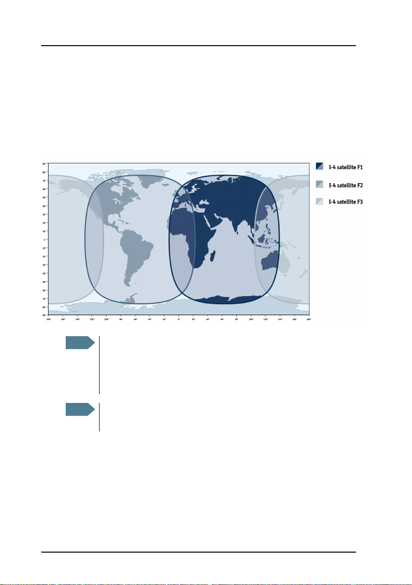
Coverage
The Inmarsat BGAN services are based on geostationary satellites situated
above the equator. Each satellite covers a certain area (footprint). The
coverage map below shows the footprints of the BGAN system.
(Launch planned
for 2008)
Note
The map depicts Inmarsat's expectations of coverage, but does not
represent a guarantee of service. The availability of service at the
edge of coverage areas fluctuates depending on various conditions.
The launch of the F3 satellite (POR) is planned for 2008.
Note
Certain FleetBroadband services are not available in areas with low
elevation. For further information, see Limitations on page 16.
12 The Inmarsat BGAN system
Page 26
Chapter 1: Introduction
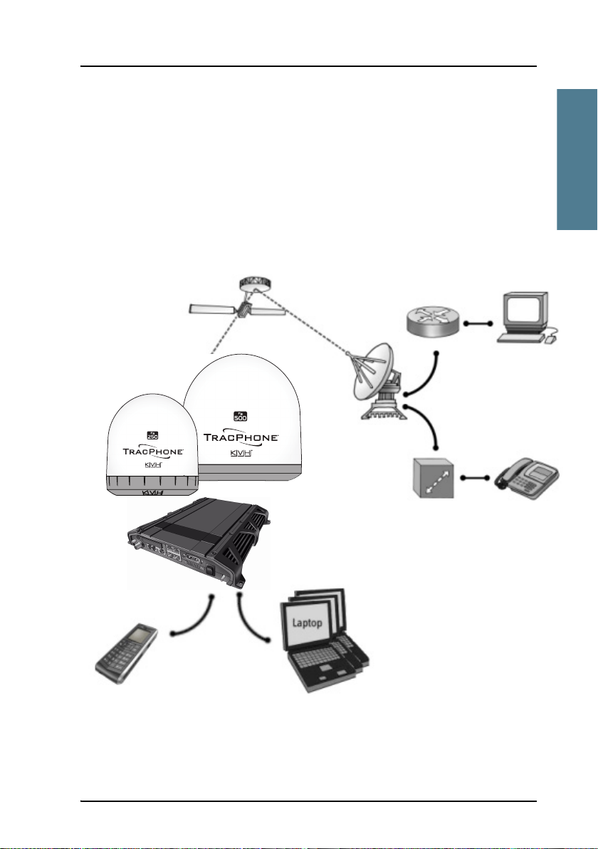
Overview of the BGAN FleetBroadband system
A complete BGAN FleetBroadband system may include the TracPhone terminal
with connected peripherals, a TracPhone FB500 antenna or a
TracPhone FB250 antenna, the BGAN satellite, and the Satellite Access Station
(SAS). The satellites are the connection between your terminal and the SAS,
which is the gateway to the worldwide networks (Internet, telephone network,
cellular network, etc.).
Packet Switched Network
Introduction
TracPhone FB250
antenna
IP Handset
Satellite
TracPhone
FleetBroadband
terminal
TracPhone FB500
antenna
IP Router
Satellite Access Station
(SAS)
Switch
PC
Standard voice
and ISDN
Circuit Switched Network
The Inmarsat BGAN system 13
Page 27

Chapter 1: Introduction
The BGAN services
Supported services
The services currently supported by BGAN comprise:
• A Packet Switched connection to the Internet
• A Circuit Switched (Dialed) connection for voice, fax or data
• Short Messaging Service (SMS)
Packet data service
The BGAN network supports different classes of data connection to the
Internet.
•Using a Standard data connection several users can share the data
connection simultaneously. This type of connection is ideal for e-mail, file
transfer, and Internet and intranet access. The user pays for the amount of
data sent and received.
•Using a Streaming data connection you get an exclusive high-priority
connection ensuring seamless transfer of data. This type of connection is
ideal for time critical applications like live video over IP. The user pays for
the duration of the connection (per minute charge).
Note
14 The Inmarsat BGAN system
The BGAN system supports maximum 11 concurrent PS connections
at a time per TracPhone system.
Page 28

Chapter 1: Introduction
Circuit switched (dialed) service
The following types of circuit switched connection are available:
• Standard Voice. A low-tariff connection for voice only. The voice signal is
compressed to 4.0 kbps, which reduces the bandwidth use and
consequently the tariff.
• 3.1 kHz Audio. A high quality connection which can be used for Premium
Voice, G3 fax or analog modems. The signal is uncompressed 3.1 kHz
audio, which allows for optimum voice quality.
• ISDN. A high quality connection which can be used for voice (3.1 kHz
Audio), G4 fax or 64 kbps UDI/RDI data.
Introduction
Note
The BGAN system only supports one CS call at a time per TracPhone
system.
SMS service
The BGAN system provides a Short Messaging Service (SMS) for sending and
receiving SMS messages.
Supplementary services
The BGAN system also provides the following supplementary services:
• Call hold
• Call waiting
•Call forwarding
•Voice mail
• Call barring
The Inmarsat BGAN system 15
Page 29
Chapter 1: Introduction
Limitations
SIM lock
The supplier may SIM lock the terminal to a specific provider. For further
information, contact your supplier.
Limitations in available services
The services available depend on your airtime subscription. Your SIM card
may not allow for all the services described in this manual.
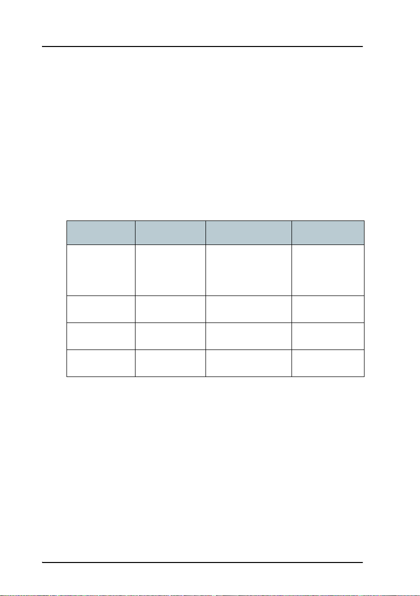
Further, for FleetBroadband Class 9 (TracPhone FB250), the following
limitations apply:
Service Elevation < 15 15 < Elevation < 20 Elevation ≥ 20
3.1 kHz Audio
for voice and
fax
ISDN Not supported Not supported Not supported
Standard IP Up to 284 kbps Up to 284 kbps Up to 284 kbps
Streaming 32, 64 kbps 32, 64, 128 kbps 32, 64, 128 kbps
For FleetBroadband Class 8 (TracPhone FB500), Streaming 256 kbps can only
be guaranteed in elevations > 15°.
Not supported Not supported Supported
16 The Inmarsat BGAN system
Page 30

Chapter 1: Introduction
Matrix of services and interfaces
The following table shows which services can be accessed from which
interfaces on the terminal, and which types of equipment can be used.
Interface on the terminal
Service
Phone/Fax LAN (PoE) ISDN
Introduction
Circuit Switched
Packet Switched
SMS
3.1 kHz
Audio
Standard
Voice
Data, UDI
or RDI
Data
multi-user
Data
single-
user
Analog
telephone
G3 Fax machine G3 Fax machine
Computer with
analog modem
Analog
telephone
IP handset ISDN telephone
IP handset ISDN telephone
G4 fax machine
or computer with
ISDN modem
Computer
Computer
IP handset or
computer with
web interface
Matrix of services and interfaces 17
Page 31

Chapter 1: Introduction
What’s next?
This chapter has provided an overview of the BGAN system and of the
TracPhone system.
The next chapters will go into more detail about how to set up and use your
system. The following chapter, Getting started, explains how to start up the
system.
18 What’s next?
Page 32

Chapter 2
Getting started 2
In this chapter
This chapter describes how to start up the system and make the first call or
data session.
For information on how to install the system, insert SIM card and connect
cables, refer to the installation manual for the TracPhone FB500 and
TracPhone FB250 systems.
Before you start
Operation at high temperatures
Getting started
In very high ambient temperatures, do not touch areas of
the terminal that are marked with this symbol.
If the terminal is installed in a location where the ambient temperature may
rise above 50°C, we recommend placing the terminal where unintentional
contact is avoided. Note that the maximum allowed ambient temperature is
55° C.
If the maximum ambient temperature does not exceed 50°C, the terminal can
be placed in a public area.
For further information on installation, refer to the installation manual for the
TracPhone systems.
19
Page 33

Chapter 2: Getting started
Connector panel
The drawing below shows the connector panel of the terminal.
L-Band ISDNPhone/Fax 1Antenna
Reset button
SIM slot
Phone/Fax 2
DC input
4 x LAN w. PoE
I/O
Power
switch
Grounding stud
For information on how to connect to each interface, refer to the installation
manual for the TracPhone FB500 and TracPhone FB250 systems.
20 Before you start
Page 34

Chapter 2: Getting started
Starting up the terminal
SIM card
Note that the TracPhone terminal requires a SIM card dedicated to
FleetBroadband. The terminal can only access the BGAN network when the
right type of SIM card is installed. For information on how to insert the SIM
card, refer to the installation manual.
Getting started
Starting up the terminal 21
Page 35

Chapter 2: Getting started
Switching on the terminal
Using the Power switch
To switch on the terminal, use the Power switch in the connector panel. It
normally takes one or two seconds for the terminal to switch on.
Using the ignition system
Normally the ignition function is not used in maritime installations. Instead
you may want to use the remote on/off function described in the next section.
If you have connected the ignition system of your vessel to the I/O connector,
you may leave the power switch in the “on” position and the terminal will
switch on/off when you start/stop the engine of your vessel. When the engine
is stopped the terminal is in standby mode, meaning that only the primary
parts of the system are kept alive. The standby current is max. 15 mA when the
ignition is off. For information on how to connect to the I/O connector, refer to
the installation manual for the TracPhone FB500 system.
You must set up the ignition function in the web interface. For further
information, see Configuring the I/O interface on page 110.
Using a remote on/off switch
If a switch is connected to the remote on/off pins in the DC connector, you may
leave the power switch in the “on” position and use the remote switch to turn
the terminal on and off. When the remote switch is off, the terminal is off.
However, if you leave the power switch on the terminal in the “on” position,
22 Starting up the terminal
Page 36

Chapter 2: Getting started
you can always switch the terminal back on with the remote switch. The
standby current when the remote switch is off is max. 2 mA. For further
information on the remote on/off function, refer to the installation manual for
the TracPhone systems.
Power up completed
When the terminal is switched on, the Power indicator in the LED panel of the
terminal lights green.
You can now access the terminal settings, but the terminal is not ready for
making calls or running data sessions until the system is registered on the
BGAN network. This normally requires that you enter a SIM PIN. For further
information, see Entering the SIM PIN for the terminal on page 26 and
Registering on the BGAN network on page 30.
Getting started
To switch off the terminal tip the Power switch back. It takes 5 to 10 seconds to
power down the terminal. Alternatively use the ignition or remote on/off
function described above.
Starting up the terminal 23
Page 37

Chapter 2: Getting started
Connecting the IP handset
Power supply
The IP handset is powered from the LAN interface, using Power over Ethernet.
Starting up the IP handset
The following procedure is for the TracPhone FleetBroadband IP handset. The
procedure may be different for another type of IP handset.
Note
Do as follows:
1. Connect the IP handset to one of the LAN (PoE) connectors on the terminal
2. If your SIM card requires a PIN and the PIN has not yet been entered in
For further information on the IP handset, refer to the user manual for the
handset.
The first handset that is connected to the LAN interface on the
terminal is automatically registered in the terminal and assigned the
local number 0501 and password 0501. For information on how to
connect additional handsets, see Connecting a new IP handset on
page 105.
as described in the user manual for the handset.
The handset starts up automatically.
the terminal, you can enter the PIN from the BGAN menu of the IP
handset.
To enter the PIN, select BGAN > Enter PIN from the handset menu system.
Note that this menu item is only available if the terminal is waiting for a
PIN. Then type in the Administrator user name and password followed by
the PIN for the terminal.
24 Connecting the IP handset
Page 38

Chapter 2: Getting started
Connecting a computer
Before connecting to the LAN interface
For the LAN interface to work without any further setup, the connected
computer must be set up to obtain an IP address and a DNS server address
automatically.
Important Notice About Your Data Connection
To prevent inadvertent airtime usage, the user must disconnect the data
connection when not in use. If the data connection is not properly
disconnected, the computer may dial out on its own, which could result in an
unintended airtime charge. KVH accepts no responsibility if this occurs. It is
the vessel owner's responsibility to ensure that the TracPhone system is
correctly interfaced with the vessel's computer(s).
Connecting a computer to the LAN interface
Do as follows:
1. Power up your computer.
2. Connect your LAN cable between the network connector on your computer
and one of the LAN connectors on the terminal.
3. When the computer and the terminal are ready, check the connection e.g.
by accessing the built-in web interface of the terminal with your browser.
For further information, see Accessing the web interface on page 60.
You may have to disable the Proxy server settings in your browser. For
further information, see Browser settings on page 58.
For information on how to configure the LAN interface on the terminal, see
Configuring the LAN interface on page 87.
Getting started
Connecting a computer 25
Page 39

Chapter 2: Getting started
Entering the SIM PIN for the terminal
Overview
Depending on your SIM card, you may have to enter a SIM PIN to use the
system. You can enter the PIN using a standard phone or ISDN phone, the IP
handset or the web interface.
For information on how to connect the IP handset or computer you are going
to use, see Connecting a computer to the LAN interface on page 25 or
Connecting the IP handset on page 24.
Entering the PIN using a phone or IP handset
To enter the PIN
If you have a phone connected to the terminal, you can use it to enter the PIN
at start up.
Do as follows:
• For an analog or ISDN phone:
Pick up the phone. When the terminal is waiting for a PIN, you will hear 2
beeps - pause - 2 beeps - etc.
Dial <PIN> followed by #.
When you hear a “busy” tone or a dialing tone, the PIN has been accepted
and you can hang up or dial a number.
• For an IP handset:
Select the BGAN menu, select Enter PIN and enter the user name and
password for the terminal. Then enter the PIN for the terminal.
Note that the menu item “Enter PIN” is only available if the terminal is
waiting for a PIN.
26 Entering the SIM PIN for the terminal
Page 40

Chapter 2: Getting started
Wrong PIN
Analog phone or ISDN phone: If, instead of the busy tone or dialing tone, you
continue to hear 2 beeps - pause - 2 beeps - etc., it means the PIN was not
accepted. Check that you have the correct PIN and try again.
If a wrong PIN has been entered three times, you will hear 3 beeps - pause - 3
beeps - etc. This means you have to enter the PUK (PIN Unblocking Key)
provided with your SIM card.
After entering the PUK, you must enter a new PIN of your own choice (4 to 8
digits long).
Dial the following:
<PUK> * <New PIN> * <New PIN> followed by # or off-hook key.
Example: If the PUK is 87654321 and the new PIN is 1234, dial
87654321 * 1234 * 1234 followed by # or off-hook key.
If you enter 10 wrong PUKs, the SIM card will no longer be functional. Contact
your Airtime Provider for a new SIM card.
IP handset: After having entered the user name and password for the terminal
you have 3 attempts to enter the SIM PIN, before you are asked to enter the
PUK (Pin Unblocking Key). The PUK is supplied with the SIM card for your
terminal.
Getting started
Enter the PUK followed by a new PIN of your own choice. The PIN must be
from 4 to 8 digits long.
If you enter a wrong PUK 10 times, the SIM card will no longer be functional,
and you have to contact your Airtime Provider for a new SIM card.
Entering the SIM PIN for the terminal 27
Page 41

Chapter 2: Getting started
Entering the PIN using the web interface
To enter the PIN
Do as follows:
1. On a computer connected to the terminal, open your browser and enter
the IP address of the terminal. Refer to Using the web interface on page 57.
The default IP address is 192.168.0.1.
If your SIM card uses a PIN and the PIN has not yet been entered, the web
interface will open on the PIN page.
2. Type in the PIN and click OK.
When the PIN is accepted, the web interface opens the Dashboard and is
ready for use. If the PIN is not accepted, see the next section Wrong PIN.
28 Entering the SIM PIN for the terminal
Page 42

Chapter 2: Getting started
Wrong PIN
You have 3 attempts to enter the PIN in the web interface, before you are
asked to enter the PUK (Pin Unblocking Key). The PUK is supplied with your
SIM card.
Enter the PUK followed by a new PIN of your own choice. The PIN must be
from 4 to 8 digits long.
If you enter a wrong PUK 10 times, the SIM card will no longer be functional,
and you have to contact your Airtime Provider for a new SIM card.
Getting started
Entering the SIM PIN for the terminal 29
Page 43

Chapter 2: Getting started
Registering on the BGAN network
Registration procedure
When the SIM PIN is accepted by the terminal, the TracPhone system starts the
registration procedure on the BGAN network.
Note
You can monitor the registration procedure by looking at the Antenna and
Terminal indicators in the LED panel of the terminal.
Note that the registration procedure may take several minutes. The table on
the next page shows the normal sequence.
We recommend keeping the vessel on a steady course while the
antenna is performing a sky scan. If the vessel is turning during sky
scan, it increases the total duration of the sky scan process.
30 Registering on the BGAN network
Page 44

Chapter 2: Getting started
LED indications during the registration procedure
This table shows how the startup procedure is signaled with the light
indicators. If an error occurs, the indicators will light yellow or red, depending
on the severity of the error.
Status Antenna indicator Terminal indicator
The antenna is starting up Flashing slowly green
The antenna is
performing a sky scan
The terminal is
registering on the
network
The antenna is tracking. Steady green
The system is registered
and ready for use.
For further information on the indicators, see Light indicators on page 163.
Flashing rapidly green
Flashing green
Steady green Steady green
Getting started
Registering on the BGAN network 31
Page 45

Chapter 2: Getting started
Making the first call
Introduction
When the Antenna and Terminal indicators in the LED panel on the terminal
both light steady green, you are ready to make or receive the first call.
The following sections provide a short guide to making calls. For more
detailed information, see Making or receiving a phone call on page 42.
Making a call from the terminal
To make a call from a phone or handset connected to the terminal, dial
00 <country code> <phone number> followed by # or off-hook key.
Example: To call the number +45 39558800 from an analog phone,
dial 00 45 39558800 #
Making a call to the terminal
Note
To make a call to a phone connected to the terminal, dial
+ <Mobile number>
• + is the prefix used in front of the country code for international calls.
32 Making the first call
By default all handsets connected to the terminal will ring on
incoming calls. If you have connected a fax, set the incoming call
type on that Phone/Fax interface to 3.1 kHz Audio to avoid that the
fax rings and answers an incoming Standard call. For further
information, see Selecting the call type on page 39.
Page 46

Chapter 2: Getting started
• Mobile number: The mobile number of the terminal you are calling. The
first part of the number is always 870, which is the “country code” for the
BGAN system.
Note
Example: If you are calling from Denmark and the mobile number for 3.1 kHz
If the mobile numbers are listed in the web interface, you can look them up by
selecting PHONE BOOK > Mobile numbers.
If the numbers are not listed, refer to your airtime subscription. We
recommend using the web interface to save the mobile numbers for future
reference. See Viewing and editing the mobile numbers on page 75.
There are two Voice numbers, one for 3.1 kHz Audio and one for
Standard Voice.
Audio is 870782105234 on your terminal, and you want to make a
call to the terminal using 3.1 kHz Audio, dial 00 870 782105234.
Making a call from one terminal to another
To make a call from one terminal to another,
dial 00 <Mobile number>.
What’s next?
After reading this chapter you should be able to start up the terminal and
make a simple data or voice connection.
Getting started
The next chapters provide more information on the user interfaces and the
setup of the terminal. The following chapter, Operating the system, explains
how to use the system.
What’s next? 33
Page 47

Chapter 2: Getting started
34 What’s next?
Page 48

Chapter 3
Operating the system 3
In this chapter
This chapter describes how to use the TracPhone systems.
It does not describe advanced configuration of interfaces. For this type of
information, refer to the “Configuring...” sections for the interfaces in Chapter
4, Using the web interface.
General
Tools for setup and use
Operating the system
Overview
You can use the IP handset for viewing status, using the phone book of the
terminal and for entering the PIN, but for enhanced use and for configuration
of interfaces, you need to connect a computer.
With a computer and a browser, you can use the built-in web interface to set
up the terminal.
35
Page 49

Chapter 3: Operating the system
The IP handset
When you connect the IP handset to one of the LAN (PoE) connectors on the
terminal you can use the handset display and keypad to enter the PIN or to
view the status of the terminal.
The IP handset includes the following items for the terminal:
• Viewing C/No (signal strength) and status (“Ready”, “Registering” etc.) for
the TracPhone system.
• Viewing the IP address and software version of the terminal.
• Viewing the IP handset settings from the terminal.
• Entering the PIN and PUK for the terminal.
• Inclusion of the terminal phone book (not editable) in the IP handset
Contacts.
For further information on the IP handset, see the user manual for the IP
handset.
The web interface of the terminal
The web interface is a built-in web server for setting up and controlling the
terminal, using a connected computer with a browser. No installation of
software is required.
With the web interface you can access the same settings as with the IP
handset, and additionally:
• edit the phone book
• view information on calls to/from the terminal
• view properties of the terminal and antenna
• set up the interfaces of the terminal
• upload software
• set up user rights (requires Administrator password)
• set up network user groups (requires Administrator password)
For information on how to use the web interface, see Using the web interface
on page 57.
36 General
Page 50

Chapter 3: Operating the system
Services and interfaces
The following table shows the possible combinations of services and
interfaces, and which types of equipment can be used.
Interface on the terminal
Service
Phone/Fax LAN (PoE) ISDN
Circuit Switched
Packet Switched
SMS
3.1 kHz
a
Audio
Standard
Voice
Data, UDI
or RDI
Data
multi-user
Data
single-user
Analog
IP handset ISDN telephone
telephone
G3 Fax machine G3 Fax machine
Computer with
analog modem
Analog
IP handset ISDN telephone
telephone
a
G4 fax machine
or computer with
ISDN modem
Computer
Computer
IP handset or
Computer with
web interface
Operating the system
a. Notes for TracPhone FB250:
UDI data is not available.
In low elevations (< 20°), 3.1 kHz Audio is not available.
General 37
Page 51

Chapter 3: Operating the system
Using a phone or fax machine
Available interfaces
Three types of voice equipment connect to the terminal:
Standard analog phone or G3 fax machine: The terminal has two phone
connectors for connecting standard analog phones or fax machines.
IP handset: The terminal has four LAN connectors with Power over Ethernet for
connecting IP handsets or other IP equipment. For information on the features
and functions of the IP handset, refer to the user manual for the handset.
ISDN phone or G4 fax machine: The terminal has one ISDN connector for
connecting an ISDN phone, a modem or a fax machine. Note that only
TracPhone FB500 supports G4 fax (UDI).
Phone/Fax 1 Phone/Fax 2 ISDN LAN
For information on how to connect to the interfaces, see the installation
manual for the TracPhone FB500 and TracPhone FB250 systems.
38 Using a phone or fax machine
Page 52

Chapter 3: Operating the system
Selecting the call type
Definition
The phone connection can use one of the following call types:
• Standard Voice, which is a low-tariff voice connection compressed to
4.0 kbps,
• 3.1 kHz Audio, which is a high quality connection used for Premium Voice,
G.3 fax or analog modem,
• UDI or RDI (only on ISDN interface), which is used for G4 fax or data.
In the web interface you can set up which type of connection to use by default
when you make or receive a call from the Phone/Fax or ISDN interface or from
an IP handset connected to the LAN interface.
When connecting a fax or a modem to the Phone/Fax interface you must use
3.1 kHz Audio.
Example: If you always have a fax connected to the same Phone/Fax
interface you can set this interface to 3.1 kHz Audio only. This will
mean that if an incoming Standard Voice call is received, this
Phone/Fax interface will not ring.
When connecting a G4 fax or a modem to the ISDN interface in the
TracPhone FB500 system you must use UDI.
Note
UDI and RDI are not available with the TracPhone FB250 system, so
you cannot connect a G4 fax machine nor a modem to the ISDN
interface on the TracPhone FB250 system.
Selecting the default outgoing call type
To select the default call type for outgoing calls, do as follows:
• ISDN. Select the call type in the web interface under SETTINGS > ISDN.
For further information, see Configuring the ISDN interface on page 92.
• Phone/Fax. Select the call type for each port in the web interface under
SETTINGS > Phone/Fax.
Operating the system
Using a phone or fax machine 39
Page 53

Chapter 3: Operating the system
For further information, see Configuring the Phone/Fax interface on
page 90.
• IP handset. Select the call type for each handset in the web interface under
SETTINGS > IP Handset > Call settings. For further information, see Setting
the call types for IP handsets on page 108.
Overriding the default outgoing call type
To override the default setting for a specific outgoing call, do as follows:
•To use Standard Voice for the call,
dial 1* before the number.
•To use 3.1 kHz Audio for the call,
dial 2* before the number.
Example: To make a call to the number +45 39558800, forcing the
connection to use Standard Voice, dial 1* 0045 39558800 followed
by # if calling from an analog or ISDN phone, or off-hook key if
calling from an IP handset.
Note
40 Using a phone or fax machine
This will not change the default call type, only the type used for the
ongoing call.
Page 54

Chapter 3: Operating the system
Phone numbers for incoming 3.1 kHz Audio and Standard Voice
3.1 kHz Audio and Standard Voice have separate phone numbers. This way, a
person calling a phone connected to the terminal can select whether to use
3.1 kHz Audio or Standard Voice, simply by using the dedicated phone
number.
Note
If the mobile numbers are listed in the web interface, you can look them up as
follows:
Connect a computer, access the web interface and select PHONE BOOK >
Mobile numbers. For further information, see Viewing and editing the mobile
numbers on page 75.
If the mobile numbers are not available in the web interface, refer to your
airtime subscription.
Note
For information on how to make a call to the terminal, see Making a call to the
terminal on page 44.
The call type you are using must be selected in the web interface
(refer to the next section).
There are two Voice numbers, one for 3.1 kHz Audio and one for
Standard Voice.
Selecting the incoming call type
To select which call types are accepted for an incoming call, use a computer
and the web interface.
• ISDN. Select the call type under SETTINGS > ISDN.
For further information, see Configuring the ISDN interface on page 92.
• Phone/Fax. Select the call type for each port under SETTINGS > Phone/Fax.
For further information, see Configuring the Phone/Fax interface on
page 90.
• IP handset. Select the call type for each handset in the web interface under
SETTINGS > IP Handset > Call settings. For further information, see Setting
the call types for IP handsets on page 108.
Operating the system
Using a phone or fax machine 41
Page 55

Chapter 3: Operating the system
Making or receiving a phone call
Analog phone, ISDN phone or IP handset
There are different methods for activating a call, depending on the type of
phone:
• Analog phone or ISDN phone: Dial # after the number.
• IP handset: Press the off-hook key after the number.
Making a call
First connect your phone to the relevant interface. For further information, see
the Installation Manual.
You have different options for making a call:
• Short Dial. If the number is in the phone book of the terminal, you can use
the Short Dial number, which is found in the first column of the phone
book in the web interface. See Short dial on page 73.
Simply dial 00 <Short Dial> followed by # or off-hook key.
Example: To call entry number 4 in the phone book,
dial 004 followed by # or off-hook key.
• Manual Dial. To make a call, dial
00 <country code> <phone number> followed by # or off-hook key.
Example: To call the number +45 39558800 from an analog or ISDN
phone, dial 00 45 39558800 #
• Call from phone book or call log (only IP handset).
• Enter the phone book of the IP handset, scroll to the wanted number
and press the off-hook key, or
• press the off-hook key from the main screen to display the latest calls
in the call log. Then scroll to the wanted number and press the offhook key again.
Note that this is the call log of the IP handset, not of the terminal.
42 Using a phone or fax machine
Page 56

Chapter 3: Operating the system
If there was an error establishing the connection, refer to the Troubleshooting
Guide on page 157.
If you are using the IP handset, the handset may show an error message.
Depending on the type of error, the web interface may also show an error
message. See Viewing the Event list or the Event log on page 150.
Receiving a call
To be able to receive a call, the phone must be connected to the relevant
interface on the terminal.
By default, all devices connected to the Phone/Fax interface, the ISDN
interface or the LAN (PoE) interface will ring when one of the mobile numbers
is called. Note, however, that this depends on the call type settings. Refer to
Selecting the incoming call type on page 41.
Call log
Information of missed calls is stored in the call log of the terminal. You can
view the call log in the web interface under CALLS. For further information,
see Viewing the lists of calls on page 77.
Operating the system
Using a phone or fax machine 43
Page 57

Chapter 3: Operating the system
Making a call to the terminal
To make a call to a phone connected to the terminal, dial
+ <Mobile number>
• + is the prefix used in front of the country code for international calls.
• Mobile number. The first part of the mobile number is always 870, which is
the “country code” for the BGAN system. If the mobile numbers are listed
in the web interface, you can look them up as follows:
Connect a computer, access the web interface and select PHONE BOOK >
Mobile numbers. For further information, see Viewing and editing the
mobile numbers on page 75.
If the mobile numbers are not available in the web interface, refer to your
airtime subscription.
Note
There are two Voice numbers, one for 3.1 kHz Audio and one for
Standard Voice.
44 Using a phone or fax machine
Page 58

Chapter 3: Operating the system
Dialing functions
Special-purpose numbers
There are a number of dialing functions available in the terminal. The
following list shows the allocated special-purpose numbers for the terminal.
Number Function
0 * followed by # or off-hook key Redial last called number on this interface.
00 * followed by # or off-hook key Redial last answered call on this interface.
Note: If the last answered number is an
unlisted number, you will not be allowed to
dial back.
00 followed by one of the numbers
1-199 and # or off-hook key
0300 followed by # or off-hook key Local call broadcast to both analog phones.
Short dial phone numbers in phone book.
Operating the system
0 followed by one of the numbers
301-302 and # or off-hook key
0400 followed by # or off-hook key Local call broadcast to all ISDN phones.
0 followed by one of the numbers
401-402 and # or off-hook key
0500 followed by # or off-hook key Local call broadcast to all IP handsets.
0 followed by one of the numbers
501-516 and # or off-hook key
0900 followed by # or off-hook key Local call broadcast to all handsets.
Using a phone or fax machine 45
Local call to analog phone.
Local call to ISDN phone.
Local call to IP handset.
Page 59

Chapter 3: Operating the system
Dialing prefixes
Apart from the numbers above, the terminal uses the following dialing
prefixes:
• 1* before the phone number will force the connection to use Standard
Voice.
• 2* before the phone number will force the connection to use 3.1 kHz
Audio.
• #31# before the phone number will hide the callers phone number to the
recipient.
• *31# before the phone number will show the callers phone number to the
recipient where it would otherwise be hidden, e.g. because the number is
an ex-directory number.
• R is used during a call to indicate that the following key-presses should
activate a supplementary services function. The supplementary services
functions supported by the terminal are described in the subsequent
sections.
Making local phone calls
You can make local calls between various phones connected to the terminal.
Local phone numbers always start with 0.
For an overview of the numbers, see Special-purpose numbers on page 45.
To make a local call, dial
<local number> followed by # or off-hook key.
Local numbers of analog phones, ISDN phones and IP handsets are assigned
according to the table in Special-purpose numbers on page 45. Note that if
you are using local numbers for ISDN devices, the numbers must be
programmed in the devices. For further information refer to the
documentation for your ISDN device.
46 Using a phone or fax machine
Page 60

Handling waiting calls
Chapter 3: Operating the system
Note
During a call, if a second party attempts to make contact with you, you may
hear a Call Waiting indication. The Call Waiting indication is two beeps and a
pause of 3 seconds, then two beeps again etc. If no action is taken, the waiting
call is released after a time out period.
In the web interface you can enable or disable the call waiting indication. For
further information, see Call waiting on page 100.
When you receive a Call Waiting indication, you have the following options:
If you want to: Do as follows:
Clear the current call,
and accept the waiting call.
Hold the current call,
and accept the waiting call.
Ignore the waiting call. Take no action.
Reject the waiting call. Press R 0 #, within the time out period.
The phone must have an R key to be able to use these functions.
Press R 1 #, within the time out period.
Press R 2 #, within the time out period.
Operating the system
Note
The BGAN system only supports one external call at a time.
Using a phone or fax machine 47
Page 61

Chapter 3: Operating the system
Holding a call
Note
During a call, you may place the initial call on hold while another call is made.
If you want to: Do as follows:
Place a call on hold. Press R 2 #.
Place the existing call on
hold and establish a new
call.
Shuttle between the two
calls.
Clear the held call, if no
waiting call exists.
Clear an active call and
return to the held call.
The phone must have an R key to be able to use these functions.
Press R and dial the second phone number
followed by #.
Press R 2 #
(irrespective of whether the second call was
acquired using Call Hold or acceptance of
Call Waiting.)
Press R 0 #.
Press R 1 #.
Note that this is only possible if no waiting
call exists.
Note
48 Using a phone or fax machine
The BGAN system only supports one external call at a time.
Page 62

Transferring a call
Chapter 3: Operating the system
Note
When you receive a call, you can transfer this call to another phone connected
to the terminal.
To transfer the incoming call to another phone or headset, do as follows:
1. Press R 4 * <local number> #.
2. You now have two options.
Note
The phone must have an R key to be able to use these functions.
The phone with the local number you dialed starts to ring.
• Hang up. The phone or headset you transferred the call to continues to
ring. When the call is answered, a connection is established between
the initial caller and the new recipient.
• Do not hang up. When the new recipient answers, you can have a
conversation before hanging up. When you hang up, the call is handed
over to the initial caller.
The BGAN system only supports one external call at a time.
Operating the system
Using a phone or fax machine 49
Page 63

Chapter 3: Operating the system
Sending or receiving a fax message
Handling delays
When sending or receiving fax messages over satellite, both fax units must be
capable of handling longer delays without timing out. Some fax machines
have an Overseas mode, which enables the unit to handle the long delays.
Sending a fax message from the terminal
Note
The fax machine must be connected to the Phone/Fax interface or the ISDN
interface of the terminal. Refer to the installation manual.
3.1 kHz Audio must be used for an analog fax machine. Refer to Selecting the
default outgoing call type on page 39.
UDI must be used for an ISDN G4 fax machine, Note that this is not possible in
a TracPhone FB250 system. Refer to Configuring the ISDN interface on
page 92.
To send a fax from a fax machine connected to the terminal, dial
00 <country code> <phone number> #
Example: To send a fax to the number +45 39558888,
If the default setting in the web interface is not 3.1 kHz Audio, you
can dial 2 * before the number, to force the connection to use 3.1 kHz
Audio. For further information, see Overriding the default outgoing
call type on page 40.
dial 00 45 39558888 #
50 Using a phone or fax machine
Page 64

Chapter 3: Operating the system
Sending a fax message to the terminal
To send a fax message to the terminal, dial
+ <Mobile number> #
• + is the prefix used in front of the country code for international calls.
• Mobile number. The first part of the mobile number is always 870, which is
the “country code” for the BGAN system. Use the 3.1 kHz mobile number if
you are calling a G3 fax and the UDI number if you are calling an ISDN G4
fax connected to the terminal. If the mobile numbers are listed in the web
interface, you can look them up as follows:
Connect a computer, access the web interface and select PHONE BOOK >
Mobile numbers. For further information, see Viewing and editing the
mobile numbers on page 75.
If the mobile numbers are not available in the web interface, refer to your
airtime subscription.
Note
There are four mobile numbers, one for 3.1 kHz Audio, one for
Standard Voice, one for UDI and one for RDI.
Receiving a fax message
Operating the system
An analog fax machine connected to the terminal can only receive a fax with
3.1 kHz Audio. Refer to Selecting the incoming call type on page 41.
An ISDN G4 fax machine connected to the TracPhone FB500 terminal can only
receive a fax with UDI. TracPhone FB250 does not support UDI and cannot be
used with a G4 fax machine.
Using a phone or fax machine 51
Page 65

Chapter 3: Operating the system
Using a computer
Interfaces
The terminal has four LAN connectors for connecting computers or other LAN
equipment.
For information on how to connect to the interfaces, see the installation
manual for the TracPhone FB500 and TracPhone FB250 systems.
Standard or Streaming data on LAN
Definition
The BGAN network supports different classes of data connection to the
Internet. The main classes are Standard data and Streaming data.
•Using a Standard data connection, several users can share the data
connection simultaneously. This type of connection is ideal for TCP/IP
traffic such as e-mail, file transfer, and Internet and intranet access.
The user pays for the amount of data sent and received.
•Using a Streaming data connection, you get an exclusive, high-priority
connection, ensuring seamless transfer of data. This type of connection is
52 Using a computer
Page 66

Chapter 3: Operating the system
ideal for time critical applications like live video over IP.
The user pays for the duration of the connection (per minute charge).
Note
For optimum performance it is important that you select the right
traffic class when defining profiles for your connection.
You can set up various types of connection using the profiles and traffic flow
filters. For further information, see Using profiles on page 139 and Using traffic
flow filters on page 143.
Setting up and activating a Streaming connection
The TracPhone FB250 system supports 32, 64 and 128 kbps Streaming.
The TracPhone FB500 system supports 32, 64, 128 and 256 kbps Streaming.
Note
By default, any data connection on the terminal is a Standard data connection.
If you want to set up a Streaming connection, select a Streaming profile when
setting up your network user group. See Managing LAN network users on
page 111.
To start or stop a Streaming session on the LAN interface, do as follows:
You may have difficulties establishing the fastest Streaming
connection if you are located close to the edges of the satellite beam.
256 kbps Streaming on TracPhone FB500 and 128 kbps Streaming on
TracPhone FB250 normally require an elevation angle of more than
15 degrees.
Operating the system
1. Access the web interface.
2. In the Dashboard, locate the field STREAMING PROFILES ON LAN.
3. Click the Start or Stop link of the relevant Streaming profile.
Note
If another primary profile is active you must stop it before you
can start your new profile.
Note
When running a Streaming session you are charged for the time
you are connected. A started Streaming session will stay active
until you stop it.
Using a computer 53
Page 67

Chapter 3: Operating the system
For further information, see Using profiles on page 139 and Setting up the
network user groups on page 113.
Working with network groups
The LAN users of the TracPhone system can be organized in network user
groups with different setup and different access rights.
Users can only see and start/stop profiles configured for their own network
user group.
Using the built-in web interface with an Administrator password you can
configure the network user groups and network devices.
For further information, see Managing LAN network users on page 111.
54 Using a computer
Page 68

Chapter 3: Operating the system
Using the IP handset
You can use the IP handset as user interface for the TracPhone system as well
as for making calls or sending SMS messages.
The IP handset has a dedicated menu for the TracPhone system.
For information on how to start up the IP handset, see Connecting the IP
handset on page 24.
For further information on how to use the IP handset, refer to the IP Handset
User Manual.
What’s next?
This chapter has described the basics of how to use the TracPhone system.
The following chapter, Using the web interface, describes how to use the builtin web interface for setting up and using the system.
Operating the system
Using the IP handset 55
Page 69

Chapter 3: Operating the system
56 What’s next?
Page 70

Chapter 4
Using the web interface 4
In this chapter
This chapter describes how to use the web interface to operate, set up and
configure your TracPhone system.
Introduction
The web interface
What is the web interface?
The web interface is built into the terminal, and is used for operating, setting
up and configuring the system.
You can access the web interface from a computer with a standard Internet
browser. Internet Explorer 6.0, Mozilla Firefox 1.0 and Apple Safari 2.0 were
tested successfully with the web interface. You may be able to use other
browser versions as well.
Connecting
Connect your computer to the terminal, using the LAN interface. For
information on how to connect to the LAN interface, see the installation
manual.
To access the web interface, an Internet browser must be installed on the
computer.
Using the web interface
57
Page 71

Chapter 4: Using the web interface
Browser settings
If you are connecting your computer using the LAN interface, the Proxy server
settings in your browser must be disabled before accessing the web interface.
Most browsers support disabling of the Proxy server settings for one specific IP
address, so you can disable Proxy server settings for the web interface only, if
you wish. Consult your browser help for information.
To disable the use of a Proxy server completely, do as follows:
Note
1. In Microsoft Internet Explorer, select Tools > Internet Options >
The following description is for Microsoft Internet Explorer. If you
are using a different browser, the procedure may be different.
Connections > LAN Settings.
58 Introduction
Page 72

Chapter 4: Using the web interface
2. Uncheck the box labeled Use a proxy server for your LAN.
3. Click OK.
When the proxy server settings are disabled, close your browser.
You may need to change this setting back on return to your Internet
connection.
Introduction 59
Using the web interface
Page 73

Chapter 4: Using the web interface
Accessing and navigating the web interface
Accessing the web interface
To access the web interface, do as follows:
1. Connect your computer to the terminal.
2. Start up the terminal.
For further information, see Getting started on page 19.
3. Open your browser and enter the IP address of the terminal.
The standard IP address is 192.168.0.1.
Note
If the IP address is changed and you do not have the new address,
you can temporarily set the IP address to the default value by
pressing the Reset button next to the SIM slot in the connector panel
of the terminal. You can then access the web interface and change
the IP address.
Note that if you do not change the IP address, the default IP address
will only be valid until the terminal is powered off. Then the terminal
returns to the IP address from before the Reset button was pressed.
For further information on the Reset button, see Reset button on
page 180.
60 Introduction
Page 74

Chapter 4: Using the web interface
Overview of the web interface
When the web interface opens, the title bar shows the name of the product.
Note
If no antenna is connected, the web interface will assume that the
system is a TracPhone FB500 system.
The web interface consists of the following sections.
Title bar
Status
field
Navigation
pane
Icon bar Contents section
Using the web interface
•The navigation pane holds the main menu. Clicking an item in the menu
opens a submenu in the navigation pane or a new page in the contents
section.
•The status field shows the signal strength.
•The icon bar shows icons for new SMS messages and for active events,
when relevant. For explanations of the icons, see the next section, Icons in
the icon bar.
•The contents section shows the page selected in the navigation pane. This
section is used for viewing or changing settings, or for performing actions.
Introduction 61
Page 75

Chapter 4: Using the web interface
Icons in the icon bar
The following icons may appear in the icon bar in the web interface:
Icon Explanation
A new SMS message, or information of Voice mail, has arrived.
Click the icon to see new messages or information of Voice mail.
For further information, see Receiving a message on page 82.
An event is active.
Click the icon to see a list of active events. For explanations of the
event messages, see List of events on page 168.
Note that this icon will remain in the icon bar as long as the
event is still active.
Navigating the web interface
• To expand a menu, click the menu in the navigation pane.
• To access status and settings, click the relevant subject in the navigation
pane or click the relevant icon in the icon bar. The status or settings are
displayed in the contents section.
• To see the site map, click SITE MAP in the navigation pane. Click on items
in the site map to go directly to the relevant location.
62 Introduction
Page 76

Chapter 4: Using the web interface
Entering the SIM PIN in the web interface
Note
If a computer is connected when you start up the terminal, you can access the
web interface and enter the SIM PIN here.
If your SIM card requires a PIN, and the PIN has not yet been entered: When
you access the web interface, it opens on the PIN page. Until you enter the PIN
you can only upload software and view the Dashboard. Access to all other
parts of the web interface requires a PIN.
You may not have to enter a SIM PIN to access the terminal. This
depends on whether or not the use of a SIM PIN is enabled on your
SIM card.
Using the web interface
Type in the PIN and click OK.
If you enter a wrong PIN 3 times you are asked for a PUK (PIN Unblocking
Key). For further information, see Wrong PIN on page 29.
If the PIN has already been entered in the terminal, or the PIN is disabled, the
web interface goes directly to the Dashboard at start-up.
Entering the SIM PIN in the web interface 63
Page 77

Chapter 4: Using the web interface
When the correct PIN is entered, the web interface opens the Dashboard and
is ready for use.
Note
Some parts of the web interface may be greyed out if the user
permissions are limited. For information on how to set up user
permissions, see Setting up user permissions on page 146.
64 Entering the SIM PIN in the web interface
Page 78

Chapter 4: Using the web interface
Using the Dashboard
Overview
The Dashboard is used for control and inspection of ongoing communication
and for viewing properties and status of the terminal and antenna.
Using the web interface
Using the Dashboard 65
Page 79

Chapter 4: Using the web interface
Properties
The PROPERTIES section of the DASHBOARD shows the following information:
• Airtime provider. The name of your Airtime Provider.
• GPS position. The GPS position of your TracPhone system.
Note
• Status. The status of the terminal and antenna.
Examples of status information are: Scanning, Ready and Data active.
• Satellite selection. The satellite selected for logon. For further information,
see Selecting the preferred BGAN satellite on page 131.
• Unit serial number. The serial number of the terminal.
• Software version. The version of the software embedded in the terminal.
• Local IP address. The local IP address of the terminal. This is the IP
address used to access the terminal from a device connected to the
terminal.
• IMEI number. The IMEI number (International Mobile Equipment Identity)
of the terminal. This is a unique number that identifies your terminal.
• MAC address for the LAN interface in the terminal.
• Antenna. The type of antenna connected to the terminal, and the status of
the antenna.
In some cases, the BGAN network does not allow the position to
be displayed to the user. If this is the case, the display may just
show GPS acquired. This means that the GPS position is received,
but the user is not allowed to see it.
This also applies if the TracPhone is not yet registered on the
BGAN network, but the GPS position is received.
66 Using the Dashboard
Page 80

Chapter 4: Using the web interface
Managing data sessions
Overview
Data sessions are displayed under PROFILES ON LAN or STREAMING PROFILES
ON LAN at the bottom of the Dashboard.
• Primary profiles are listed in the left side and secondary profiles (if any)
are listed to the right.
• Profiles that are currently active are displayed as a link with the text “Stop
<name of profile>”.
• Profiles that are ready to be activated are displayed as a link with the text
“Start <name of profile>”.
Using the web interface
Using the Dashboard 67
Page 81

Chapter 4: Using the web interface
Start/stop a Streaming session on the LAN interface
Note
Before starting a Streaming session, make sure you have set up a
Streaming profile for your user group in the SETTINGS > LAN >
Network user groups page.
To start or stop a Streaming session, click the link with the name of your
Streaming profile under STREAMING PROFILES ON LAN.
Note that if another primary profile is active you must stop it before you can
start your new profile!
If a primary profile is already active, your new profile will not appear as a link
but as plain text. The active primary profile is displayed as a link with the text
“Stop <name of profile>”. Click this link first to stop the active profile. Then
click your new profile, which is now displayed as a link.
Important
If you have selected a Streaming connection as your primary
profile, the LAN interface will be running a Streaming
connection until you stop it or disconnect the interface.
However, if you select one or more secondary profiles, you can
set up your traffic flow filter so that it will only use the
Streaming profile for certain types of traffic.
For information on setup of the network user groups, see Managing LAN
network users on page 111. For information on how to set up a profile, see
Using profiles on page 139.
Note
You may have difficulties establishing the fastest Streaming
connection if you are located close to the edges of the satellite beam.
256 kbps Streaming on TracPhone FB500 and 128 kbps Streaming on
TracPhone FB250 normally require an elevation angle of more than
15 degrees.
68 Using the Dashboard
Page 82

Chapter 4: Using the web interface
Start/stop Standard data on the LAN interface
By default, Standard data is always activated on the terminal. If you only want
Standard data to be activated when you have specifically enabled it, you can
disable automatic activation using the SETTINGS > LAN > Network user groups
page.
When automatic activation is disabled in the Network user groups page, you
can manually start/stop your Standard data profile from the Dashboard by
clicking Start <name of profile> or Stop <name of profile> under PROFILES ON
LAN at the bottom of the page.
Note
If a primary profile is already active, your new profile will not appear as a link
but as plain text. The active primary profile is displayed as a link with the text
“Stop <name of profile>”. Click this link first to stop the active profile. Then
click your new profile, which is now displayed as a link.
If another primary profile is active you must stop it before you can
start your new profile.
Using the web interface
Using the Dashboard 69
Page 83

Chapter 4: Using the web interface
Viewing information on calls and data sessions
The following sections in the Dashboard show information on calls and data
sessions.
• ONGOING CALLS is a list of calls that are currently active. The list shows the
call type and the time connected for each call.
• ONGOING DATA SESSIONS is a list of data profiles that are currently active,
including the IP address that is assigned to each profile.
• SESSIONS TOTAL lists the totals for each connection. The list shows the
time connected for voice and Streaming data, and MB transferred for
Standard data.
The counters show totals for connections since the counters were last cleared.
70 Using the Dashboard
Page 84

Chapter 4: Using the web interface
Using the phone book
General usage
Overview
In the phone book you can:
• Look up phone numbers.
• Look up short dial numbers for easy dialing from a handset.
• Modify or delete existing names and phone numbers, or enter new names
and phone numbers.
Using the phone book 71
Using the web interface
Page 85

Chapter 4: Using the web interface
Accessing the phone book
To access the phone book, select PHONE BOOK from the left navigation pane.
The phone book shows all entries with entry number, name and phone
number. Empty place holders are also included.
To sort the phone book, click the title of the column you wish to sort by. For
example, to sort by the names in the phone book alphabetically, click on Name
in the top row of the phone book.
The phone book holds 199 entries divided into subpages. To select the
subpages you want, click the relevant link at the bottom of the page.
72 Using the phone book
Page 86

Chapter 4: Using the web interface
Short dial
The entry number in the phone book is the Short dial number. When making a
call from the terminal you can use this number instead of dialing the entire
phone number.
Simply dial 00 <short dial> followed by # or off-hook key.
Example: To call the third entry in the phone book from an analog phone,
take the phone off hook and dial 003 #.
Using the phone book 73
Using the web interface
Page 87

Chapter 4: Using the web interface
Editing phone book entries
Adding a new entry
To add a new entry, do as follows:
1. In the phone book, locate the empty entry number where you want to add
the new phone number and click New.
2. Type in the name and phone number of the new entry and click Save
entry.
The new name and number are now listed at the specified entry number in
the phone book.
Modifying an entry in the phone book
To modify an entry, do as follows:
1. In the phone book, click Edit next to the entry you want to modify.
2. Modify the name or number as wanted and click Save entry.
The name and/or number in the selected entry is now replaced with the
new information.
Deleting an entry in the phone book
To delete an entry, click Delete next to the entry you want to delete.
Deleting all entries in the phone book
To delete all the entries in the phone book, click Delete all entries in phone
book at the bottom of the PHONE BOOK page.
74 Using the phone book
Page 88

Chapter 4: Using the web interface
Viewing and editing the mobile numbers
To view the mobile numbers
To view the mobile numbers of the terminal, select PHONE BOOK > Mobile
numbers from the left navigation pane. The mobile numbers are the phone
numbers to use when making a call to the terminal.
Note
These numbers are not listed at delivery. The user must enter the
numbers received from the Airtime Provider.
To enter or edit the mobile numbers
Using the web interface
To enter or edit the mobile numbers, click Edit at the bottom of the page, type
in the numbers received from your Airtime Provider and click OK.
Using the phone book 75
Page 89

Chapter 4: Using the web interface
Using the Call log
Note
If power to the terminal is interrupted, all information on calls since
last power up is lost. This could mean that you will be charged for
more calls than the number of calls registered in the call log.
Information on total usage
To enter the CALLS page select CALLS from the left navigation pane. The CALLS
page contains information on usage for circuit switched connections.
For an explanation of the circuit switched services, see Circuit switched
(dialed) service on page 15.
The listed information includes:
• Time connected using Standard Voice and
• time connected using 3.1 kHz Audio.
76 Using the Call log
Page 90

Chapter 4: Using the web interface
Exporting the call log
The system logs all calls and data sessions. For information on how to view the
lists of calls and data sessions, see the next section.
To export the entire call log to a file, do as follows:
1. In the CALLS page, click the link Export call log to file.
2. Browse to the location where you want to save the log.
3. Click OK.
Viewing the lists of calls
To see information on outgoing, received or missed calls or data sessions,
select one of the following lists from the left navigation pane in the CALLS
page:
• Outgoing calls shows the start time, receiving end phone number,
duration, type (Standard or 3.1 kHz Audio) and estimated charge of each
outgoing call.
• Received calls shows the start time, calling phone number, duration and
type (Standard or 3.1 kHz Audio) of each incoming call.
• Missed calls shows the start time, calling phone number and type
(Standard or 3.1 kHz Audio) of each incoming call that was not received.
• Standard data sessions shows the start time, bytes in, bytes out and
estimated charge of each Standard data session.
• Streaming data sessions shows the start time, duration, type (Streaming
32, 64, 128 or 256 kbps) and estimated charge of each Streaming data
session.
Using the web interface
Date and time is UTC time, received from the satellite.
Using the Call log 77
Page 91

Chapter 4: Using the web interface
For information on the available types of service, see The BGAN services on
page 14.
Note
The estimated charge is based on your entries under
ADMINISTRATION > Call charges. KVH Industries does not take
responsibility for the correctness of this estimated charge.
You can sort each of the lists by clicking the title of the column you wish to sort
by.
If a list covers more than one page, you can click the relevant link at the
bottom of the page, to go to another page.
When there are more than 100 calls in the total list, the oldest calls are
automatically removed to make room for new calls.
78 Using the Call log
Page 92

Handling SMS messages
Sending an SMS message
Chapter 4: Using the web interface
Important
To send an SMS message from the terminal, do as follows:
1. Click MESSAGES from the left navigation pane.
This page contains new incoming messages.
2. In the left navigation pane, click Write message.
If the terminal is not online when you attempt to send a
message, the message is moved to the Outbox in stead of the
Sent folder. Messages in the Outbox are not automatically sent
when the terminal goes online. For further information on the
Outbox, see the next section, Options for messages in the
Outbox.
To make sure a message has been sent, check that it has been
moved to the Sent folder.
Using the web interface
Handling SMS messages 79
Page 93

Chapter 4: Using the web interface
3. Type in the message in the Write new message field.
If the message text is too long for one SMS, the message is sent as two or
more SMS messages. The field below the message field shows the number
of SMS messages used to send the message.
4. Type in the phone number in the Recipient field.
Remember 00 and country code (e.g. 00 45 to call Denmark or 00 1 to call
USA).
5. Select whether or not you want Delivery notification for this SMS message.
If you click Yes, the Status column in the Sent folder will show the status of
your message when it has been sent.
You can set up delivery notification generally for all SMS messages. This
setting is used by default when you send a message. For further
information, see Configuring message settings on page 84.
6. Click Send.
The message is now sent and moved to the Sent folder.
Options for messages in the Outbox
Messages in the Outbox are messages that have not been sent, e.g. because
the terminal was not online when you attempted to send the messages.
To access the Outbox, click MESSAGES > Outbox from the navigation pane.
You have the following options for messages in the Outbox:
• When the terminal is online, click Resend next to the message you want to
send. When the Write message page opens, click Send.
The terminal now attempts to send the message again. To make sure the
message has been sent, look in the Sent folder.
Note
• Click Delete next to a message to delete it.
• Click Delete all messages in Outbox to delete all the messages.
80 Handling SMS messages
The original message remains in the Outbox. When you have
succeeded in sending the message you may want to delete it
from the Outbox.
Page 94

Chapter 4: Using the web interface
Options for messages in the Sent folder
The Sent folder contains SMS messages that have been sent.
To access the Sent folder, select MESSAGES > Sent from the navigation pane.
The Status column shows the status of each message, if you have selected
Delivery notification when sending the message.
From the Sent folder you have the following options:
• Click Resend next to a message you want to send again.
When the Write message page opens, click Send.
The terminal now attempts to send the message again. To make sure the
message has been sent, look in the Sent folder. There should now be two
copies of the sent message.
• Click Forward next to a message you want to forward.
Type in the phone number of the new recipient and click Send.
The terminal now attempts to send the message to the new recipient. To
make sure the message has been sent, look in the Sent folder.
• Click Delete next to a message to delete it.
• Click Delete all sent messages to delete all the messages.
Using the web interface
Sending an SMS message to the terminal
You can send an SMS message to the terminal e.g. from a mobile phone,
using one of the mobile numbers for voice. Dial
+ <Mobile number>
The first part of the mobile number is always 870, which is the “country code”
for the BGAN system. If the mobile numbers are listed in the web interface,
you can look them up as follows:
Select PHONE BOOK > Mobile numbers. If the mobile numbers are not listed in
the web interface, refer to your airtime subscription.
Note
There are two Voice numbers, one for 3.1 kHz Audio and one for
Standard Voice.
Handling SMS messages 81
Page 95

Chapter 4: Using the web interface
Receiving a message
If a message has arrived, the icon bar at the top of the web interface shows an
unopened envelope. Click the envelope to see the new message(s).
Otherwise, to see new messages click MESSAGES from the left navigation
pane.
The page shows new incoming messages.
Note
If the message is not an SMS message but information of voice mail, call your
voice mail service number to hear the voice mail.
To find your voice mail number, select MESSAGES > Message settings from the
left navigation pane and locate the Voice mail number.
Note that the voice mail number is only shown if it is available on the SIM
card. Otherwise, refer to the information included with your Airtime
subscription.
The terminal does not accept more than 100 incoming messages
(including read and unread messages). If you have received 100
messages, you have to delete some of them in order to free space
for new messages. Otherwise, the new messages are rejected.
82 Handling SMS messages
Page 96

Chapter 4: Using the web interface
Options for new SMS messages
To see new messages, click MESSAGES from the left navigation pane.
Besides viewing the new messages, you have a number of options for what to
do with each message:
• Click Read to move it to your Inbox containing read messages.
• Click Reply to reply to a message.
Then type in your reply and click Send.
For information on how to include the original message in your reply, see
Setting up the default message options on page 84.
• Click Forward to forward a message to someone.
Then type in the phone number in the Recipient field and click Send.
• If you want to move all the new messages, click Move all new messages to
Inbox.
Note
New messages cannot be deleted until they have been moved to
the Inbox.
Options for SMS messages in the Inbox
The messages in the Inbox are the incoming messages that have been read
and moved from the list of new messages (refer to the previous section).
From the Inbox, you have the following options:
• Click Reply to reply to a message.
Then type in your reply and click Send.
For information on how to include the original message in your reply, see
Setting up the default message options on page 84.
• Click Forward to forward a message to someone.
Then type in the phone number in the Recipient field and click Send.
• Click Delete to delete the message.
• Click Delete all messages in Inbox to delete all read messages in the Inbox.
Using the web interface
Handling SMS messages 83
Page 97

Chapter 4: Using the web interface
Configuring message settings
Setting up the default message options
You can set up general options for your outgoing messages. These settings
apply by default to all your outgoing messages. Note, however, that you can
change the Delivery notification setting for an individual message. For further
information, see Sending an SMS message on page 79.
Do as follows:
1. Select MESSAGES > Message settings from the left navigation pane.
2. If you want to include the original message when you reply, select Yes
next to Include message in reply.
3. Select whether or not you want Delivery notification for SMS messages.
If you click Yes, the Status column in the Sent folder will show the status of
your message when it has been sent.
4. Click Apply.
84 Handling SMS messages
Page 98

Chapter 4: Using the web interface
Viewing or changing SMS service center number
The SMS service center number identifies the SMS service center used when
sending and receiving SMS messages. The SMS service center number is
stored on the SIM card.
• To see the SMS service center number, select
MESSAGES > Message settings from the left navigation pane.
• To change the number, click Edit next to SMS service center, change the
number and click Save. Then click Apply to apply all changes in the page.
The SMS service center number is provided from your Airtime Provider.
Viewing the Voice mail number
The Voice mail number is the number you call to hear your incoming voice
mails.
Note
To see the Voice mail number, select
MESSAGES > Message settings from the left navigation pane. The Voice mail
number field shows the Voice mail number.
The Voice mail number is only listed if it is available on the SIM
card. Otherwise, refer to the information included with your Airtime
subscription.
Handling SMS messages 85
Using the web interface
Page 99

Chapter 4: Using the web interface
Setting up the interfaces
The SETTINGS page (Antenna properties)
The SETTINGS page shows properties of the connected antenna and contains a
field for enabling or disabling the L-Band interface on the terminal.
To access the SETTINGS page, select SETTINGS from the left navigation pane.
Enabling or disabling the L-Band interface
The L-Band interface is used for connecting a broadband receiver for
reception of position data. To enable or disable the L-Band interface, do as
follows:
1. In the L-BAND CONNECTOR field of the SETTINGS page, select Enable or
Disable.
2. Click Apply.
86 Setting up the interfaces
Page 100

Chapter 4: Using the web interface
Configuring the LAN interface
Overview
The TracPhone terminal has 4 LAN connectors with PoE (Power over Ethernet).
The major part of the LAN parameters are set up in the network management
pages. For information on these settings, refer to Managing LAN network
users on page 111.
Caution! All connections to the LAN interface may be affected when
you change the settings below. This also includes your own
current connection.
Setting up the interfaces 87
Using the web interface
 Loading...