

Kverneland NGH 301, NGH 401, NGH 351, NGS 401, NGS 301 Instruction Manual
...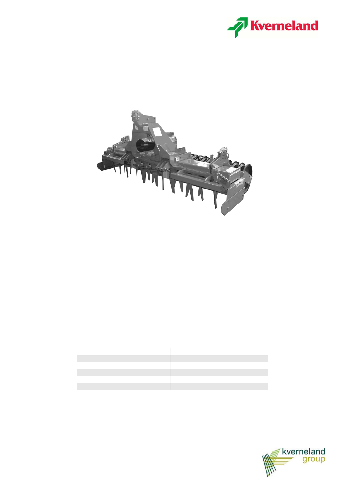
NGH 301-351-401
NGS 301-401-451
Instruction manual
Edition
Print
Language EN
from machine number
Article code
06/2014
06/2014
MUM78EN08

Machine identification
To enable your dealer to help quickly and efficiently, you need to supply certain information about your machine. Use the spaces below to record this information.
Designation
NG............
Serial number
Accessories
Dealer's address
Manufacturer's address
Kverneland Group Modena
Strada Ponte Alto, 74
41100 Modena
ITALIA
Telefono +39 059 380 511
Copyright owned by Kvernel and Gr oup Mode na, I TALY. A ll c opying , tr anscri ption to o ther me dia, t rans latio n and use of extr acts o r par ts is prohibited without the express authorization of Kverneland. All right reserved. The contents of this instruction manual are subject to modifcation without prior notice. We reserve t he right to make technical modifcations.

Contents
Contents
Introduction . . . . . . . . . . . . . . . . . . . . . . . . . . 4
About this manual 4
Meaning of symbols 4
Safety . . . . . . . . . . . . . . . . . . . . . . . . . . . . . . . 5
For your safety 5
Other regulations to be observed 5
Safety symbols 5
Meanings of the safety symbols 5
Positions of the safety warning labels 7
Sound pressure levels 7
Lifting 8
Getting to know your machine . . . . . . . . . . 9
Intended use 9
Key to parts 9
Technical specifications 10
Delivery and preparation of the
machine . . . . . . . . . . . . . . . . . . . . . . . . . . . . 11
Checking the machine 11
Preparation 11
Universal seed drill attachment 32
Hydraulic seed drill attachment 34
Accord seed drill triangular mounting
frame 36
Troubleshooting . . . . . . . . . . . . . . . . . . . . . 37
Warranty . . . . . . . . . . . . . . . . . . . . . . . . . . . . 38
Guide to warranty conditions 38
Service information 38
Disposal of the machine . . . . . . . . . . . . . . . 39
EC Declaration of Conformity . . . . . . . . . . 40
Index . . . . . . . . . . . . . . . . . . . . . . . . . . . . . . . 43
Hitching the machine . . . . . . . . . . . . . . . . . 13
Preparation for work . . . . . . . . . . . . . . . . . 16
Checking the oil levels 16
Working speed 17
Speed selection 18
Transporting the implement on
the road . . . . . . . . . . . . . . . . . . . . . . . . . . . . 20
Preparations in the field . . . . . . . . . . . . . . . 21
Lateral stone guards 21
Adjusting the working depth 21
Adjustment of the levelling bar 22
Positioning the track eradicator 23
Cleaning, care and storage . . . . . . . . . . . . 24
Safe storage 24
Winter storage 24
Maintenance . . . . . . . . . . . . . . . . . . . . . . . . 25
Changing the oil 25
Comparative classification of viscosity 27
Replacing the tines of the harrow 28
Packer roller 29
Disc rollers 30
Accessories . . . . . . . . . . . . . . . . . . . . . . . . 32
3

Introduction
Introduction
Introduction
About this manual
Training
This Instruction Manual is addressed to qualified users or experienced
agricultural operatives who have received suit able tra ining on the use
of the machine.
For your safety
Before hitching up or operating the machine, please familiarise
yourself with the contents of this Instruction Manual. This will ensure
that you achieve optimum results and work in conditions of safe ty.
The manufacturer accepts no liability for any damage or operating
problems caused by failure to adhere to the instructions given in this
manual.
For the employer
All personnel must receive proper training in the use of the machine
(at least once a year) in accordance with the guidelines on safety at
work.
Unauthorized and untrained persons are prohibited from using the
machine.
Your dealer will provide instructions on the operation and care of the
machine.
Meaning of
symbols
NOTE
The following symbols are used in this manual as an aid to
comprehension:
• a bullet point denotes the individual items in a list
> a triangle indicates the operations to be carried out
-->an arrow refers the reader to informa tion in other sections of the
manual
Furthermore, other graphic symbols are used to help the reade r to find
the relative instructions more quickly:
The term "Note" is used to indicate suggestions and notes on use of
the machine.
The wrench symbol denotes suggestions for attachment or
adjustment of the machine.
The warning triangle is used to highlight important safety warnings.
Failure to observe these warnings may result in:
• Serious malfunction of the machine
• Damage to the machine
• Personal injury or accidents
An asterisk indicates examples provided to aid comprehension of the
instructions in the text.
44

Safety
Safety
Safety
For your safety
Other regulations
to be observed
This section contains general safety warnings. The individual sections
of manual contain additional specific safety warnings which are not
included in this section. Take particular care to observe the safety
warnings
• for your own personal safety
• for the safety of other persons and
• to prevent damage to the machine.
Improper use of the machine and other agricultural equipment can
create serious hazards. Always work with maxium care and attention
and never in haste.
The employer should:
At regular intervals and in accordance with legal requirements, ensur e
that all persons working with the machine are informed of these safety
warnings.
Respect regulations
In addition to these warnings, you must also observe:
• accident prevention regulations
• technical rules for safety, occupational health and the highway
code
• the warnings contained in this Instruction Manual
• the instructions for use, maintenance and repair.
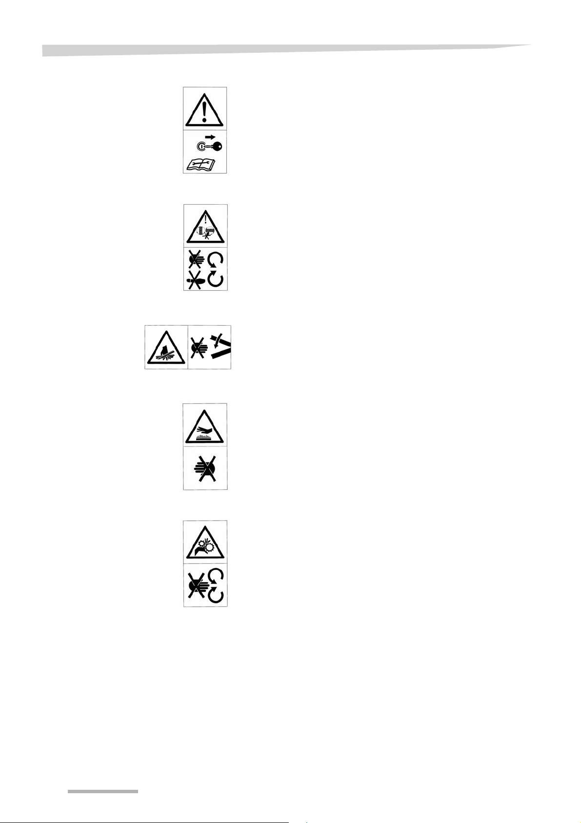
Safety symbols
Meanings of the
safety symbols
Adhesive labels bearing safety symbols are affixed to the machine to
warn the operator of potential hazards.
Observe the safety warnings!
Always:
• Keep the safety warning labels clean and legible
• Replace any damaged or missing labels
Read the instructions
Read the Instruction Manual and the safety warnings carefully before
putting the machine into service. Keep this manual in a safe place.
Adhesive label code: ZD75500710
55
Safety
Safety
Switch off the engine and remove the starter key
Before proceeding with any maintenance or repair operations, first
switch off the engine and remove the key fr om the st a rter switch, then
consult the instruction manual
Adhesive label code: ZD75500711
Keep clear of moving parts
Rotating parts hazard.
Keep hands and feet clear
Adhesive label code: ZD75500713
Keep clear of moving parts
Crushing hazard.
Keep hands clear of the danger zone.
Wait until all moving parts have come to a complete stop
Adhesive label code: ZD75500703
Keep clear of hot surfaces
Keep a safe distance from hot surfaces
Adhesive label code: ZD75500706
Moving parts
Do not lean over the moving parts of the transmission.
Do not open or remove the safety shields when the engine is running
Adhesive label code: ZD75500708
66
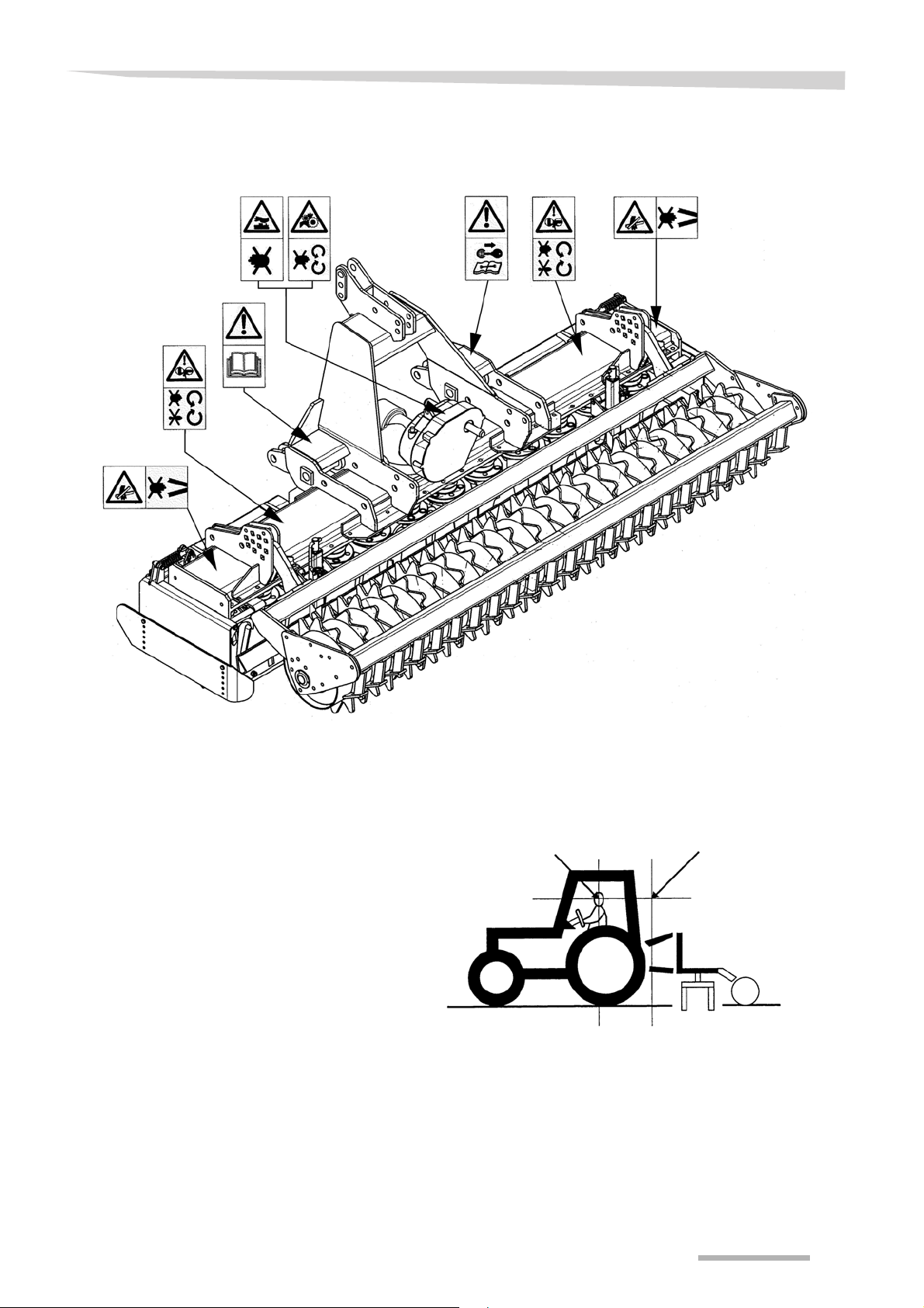
Positions of the
safety warning labels
Safety
Safety
Sound pressure
levels
Microphone1
Measured values Tractor only Tractor+implement
cab open open
Microphone 1 92 dB (A) 96 dB (A)
Microphone 2 92 dB (A) 94 dB (A)
Microphone 2
height of
measurement
77
Safety
Safety
Lifting
Observe safety rules!
Do not stand under suspended loads
T ake all necessary precautions to prevent injury or damage caused by
accidental falls
When using a crane or other lifting equipment, the harrow must be
attached at the upper mounting as shown in the figure
88
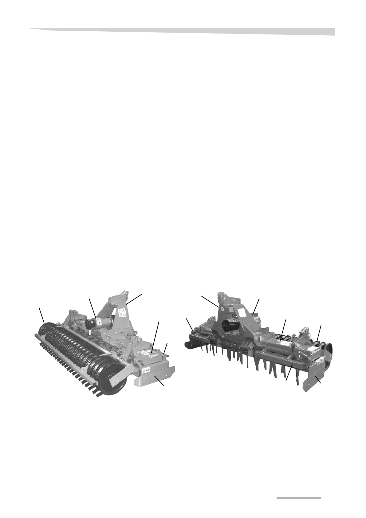
Getting to know your machine
Getting to know your machine
Intended use
Key to parts
This section contains general information on the machine and
information on:
Getting to know your machine
• characteristics
• Technical specifications
The NGH and NGS harrows have been designed and built for the
usual agricultural applications. Any other use is to be considered
improper.
Standard machine
• Transmission casing (Ref.1):
3.0m - 12 tine holders - 24 tines (NGH 301 and NGS 301)
3.5m - 14 tine holders - 28 tines (NGH 351)
4.0m - 16 tine holders - 32 tines (NGH 401 and NGS 401)
4.5m - 18 tine holders - 36 tines (NGS 451)
• Frame for attachment to 3-point hitch of the tr actor, with floating or
fixed lower mountings (Ref.2):
Cat.II for model NGH 301
Cat.II + III for models NGH 351, NGH 401 and NGS 301 - 401 - 451.
• Gearbox with exchange speed change or lever change
(OPTIONAL) (Ref.3)
• Lateral stone guards with spring (Ref.4)
• Safety guards (Ref.5)
NGH 301-351-401 NGS 301-401-451
3
2
6
1
5
4
Accessories
The NGH and NGS harrows can be equipped with a wide range of
optional accessories, such as, for example, different drive shafts and
different rollers (Ref.6), all of which may be ordered from your dealer.
2
4
3
1
5
6
4
99

Getting to know your machine
Getting to know your machine
Technical
specifications
Identification plate
All machines carry an identification plate which indicates:
• the type of machine (Ref. A),
• the model (Ref. B),
• the serial number (Ref. C),
• the year of manufacture (Ref. D),
• the weight in kg (Ref. E)
General characteristics NGH
MODEL
NGH 301
NGH 351 3.50 m 1836 Kg
NGH 401 4.00 m 2046 Kg
Maximum tractor
power
131 kw/ 180 HP exchange speed
Type of gearbox
Working
width
3.00 m 1626 Kg
Machine weight with Ø500 mm
packer roller, wit
approx. values)
(
General characteristics NGS
MODEL
NGS 301
NGS 401 4.00 m 2275 Kg
NGS 451 4.50 m
Maximum tractor
power
183 kw / 250 HP exchange speed
Type of gearbox
Working
width
3.00 m 1836 Kg
Machine weight with Ø500 mm
packer roller, without drive shaft
(approx. values)
hout drive shaft
2514 Kg
1010

Delivery and preparation of the machine
Delivery and preparation of the machine
Delivery and preparation of the machine
Checking the
machine
Pre-delivery checks
On delivery, check that all parts of the machine are present and that
they have not been damaged in transit; notify your dealer, importer or
the manufacturer immediately of any defects found.
NOTE For shipping purposes, some of the components may be supplied
pre-assembled on the machine, while others may be fixed temporar ily .
The machine leaves the Manufa cturer with all parts in fully working
order. In all cases, it is the Retailer's responsibility to check the
following upon delivery to the User:
• the three-point attachment is correctly mounted,
• the grease in the transmission unit and the oil in gearbox are at
prescribed levels,
• grease injected into the greasers is present,
• all adhesive safety labels indicated in the present booklet must be
present and legible,
• screws and bolts must be securely tightened,
• EEC-compliant guards are provided,
• the machine must be free of imperfections up o n gene r al
inspection.
Preparation
The Retailer must draw the user's attent ion to this manual and the
drive shaft manual also provided, which must both be kept by the user
throughout the machine's service life. The Retailer is also responsible
for recommending that the user reads these manuals carefully.
Risk of crushing and cuts!
During machine preparation operations, o bserve the SAFETY rules, in
particular:
• make sure that the machine is in a very stable position.
• Do not stand between the tractor and the machine during h itching
or unhitching operations. If it is necessary to work in the area
between the tractor and the machine, observe the safety rules
(tractor engine switched off, Pto disengaged, tractor parking brake
applied, key removed from starter switch, chocks placed under
wheels of the tractor)
• Before hitching or unhitching the machine to/from the tractor,
position the lift control lever in a position where it is not possible to
operate it.
• Do not stand under suspended loads
• Take all necessary precautions to prevent injury or damage
caused by accidental falls
Reposition and securely fix in working position all those parts of the
machine that were secured in temporary positions for shipment.
Positioning the roller
for work
When supplied with the machine, the roller is secured in transport
position; to position the roller in the correct working position, proceed
as follows:
1111
Delivery and preparation of the machine
Delivery and preparation of the machine
>
Support the roller, observing safety rules
>
Unscrew the nuts securing the arms and remove the bolts
Caution: suspended load hazard!
>
Move the arms and the roller into the correct position (see figure) and
replace the bolts
>
Replace the nuts and tighten
Working position Transport position
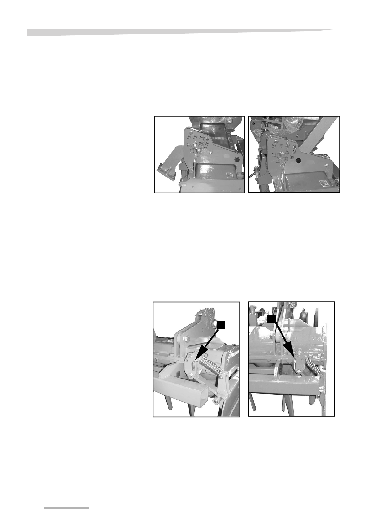
Positioning the
lateral stone guards
for work
The stone guards are secured in transport position for shipment; to
position the two stone guards in the correct working position, proceed
as follows:
Remove the locking pin from the pivot pin (7)
>
>
Remove the pivot pin (7) from the transport position hole
>
Raise the stone guard
>
Insert the pivot pin (7) in the working position hole
>
Reinsert the locking pin in the pivot pin
Working position Transport position
7
7
1212
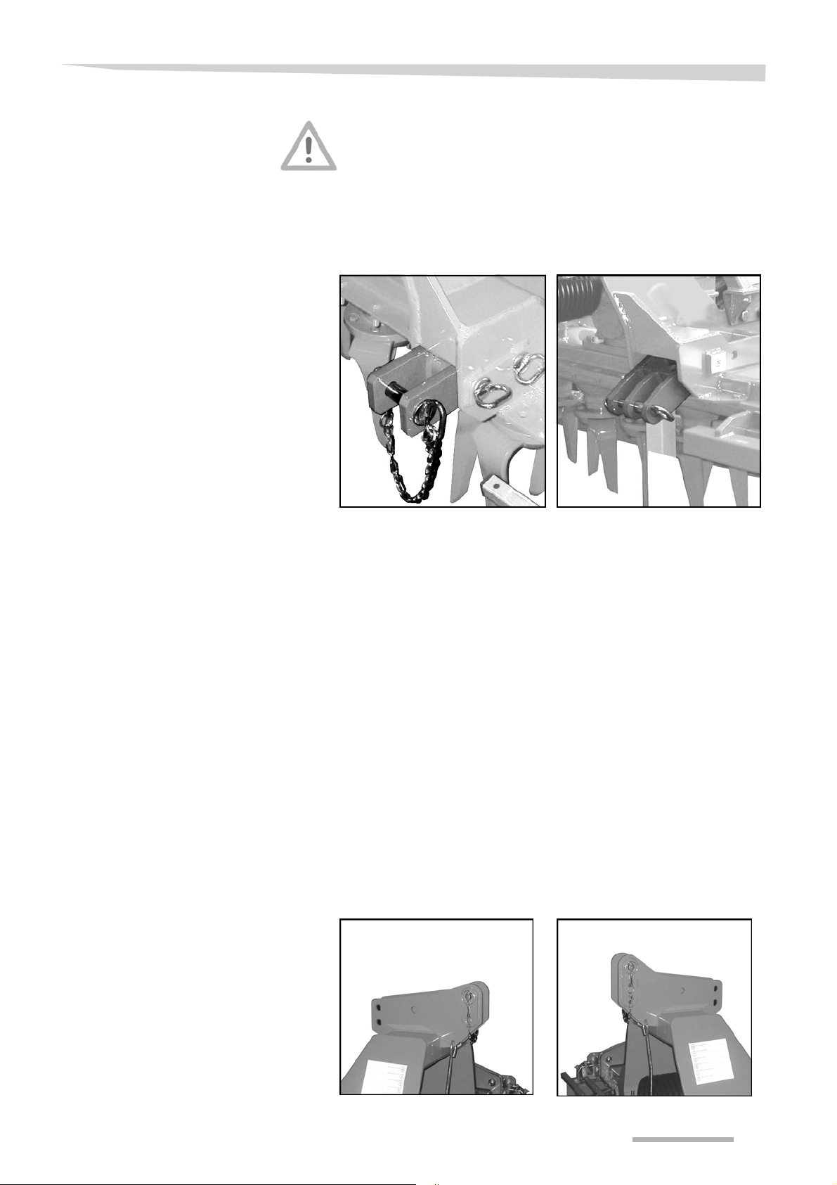
Hitching the machine
Hitching the machine
We strongly recommend that you observe the safety warnings given
in the previous pages of this manual.
The category of the tractor 3-point linkage must match that of the
implement.
Mounting bracket
for Cat.2 linkage
Mounting bracket
for Cat.2+3 linkage
Hitching the machine
To attach the harrow to the tractor, proceed as follows:
Line up the tractor with the harrow
>
>
Insert the lower links of the tractor's hydraulic linkage in the corresponding
mounting brackets on the implement, which should both be positioned at
the same distance from the tractor.
>
Secure the lower links with the pins and locking pins provided.
NOTE Attachment is made easier if the lower link stabilisers are adjusted so
as to allow the lower links to move freely.
On completion of the hitching operation, the stabilisers should be
adjusted so as to limit oscillation (during implement transport, all
oscillation must be completely eliminated).
Insert the end of the top link of the tractor's hydraulic linkage in the upper
>
mounting bracket of the harrow and secure it with the relative pins and
locking pins.
>
Adjust the length of the top link, bearing in mind that the drive shaft
transmitting power from the tractor Pto to the harrow must be horizontal
when the implement is in operation.
NGH NGS
1313
 Loading...