

Kverneland Miniair Nova Operating Manual
Miniair Nova
Operating manual
Edition 9/2011
Print 11.2011
Language EN [Original]
From machine number ACPNPxx1940
Explanation Foldable
Product number AC758881

Identification of the machine
Your dealer requires some information about your machine in order to be able to help you as quickly as possible.
Please enter the information here.
Designation
Working width
Weight
Machine number
Accessory
Address of dealer
Miniair Nova
Address of manufacturer
Kverneland Group Soest GmbH
Coesterweg 42
D-59 494 Soest
Tel: +49 (0)2921 / 974-0
Copyright by Kverneland Soest GmbH, Germany. Reproduction, transfer to other media, translation or the use of extracts or parts of this manual
without the explicit permission of Kverneland, is not permitted. All rights reserved. The content s of this operating ma nual are subject to chang e
without notice. The right to technical revision is reserved.

Table of Contents
Preliminary information..................................5
Target group for this operating manual 5
Meaning of the symbols 5
Safety................................................................6
For your safety 6
Safety stickers 6
Who is allowed to operate the machine? 11
Coupling 11
Centre of gravity 12
Road transport 14
Putting the machine into operation 14
Uncoupling the machine 16
Care and maintenance 16
Further regulations 17
Getting to know the machine .......................18
Range of application of the machine 18
Proper use 18
Definitions 18
Characteristics of the machine 19
Component designations 20
Technical specifications 25
Delivery and assembly..................................28
Check scope of supply 28
Coupling the machinery................................29
Coupling the machine 29
Connections 29
Preparing for operation.................................33
General 33
Frame 34
Track marker [+] 36
Adjust sowing units 42
Setting of the grain distance 46
Adjusting the seed coverer 51
Adjusting the intermediate press wheel [+] 53
Adjusting the clod deflector [+] 54
Adjusting double seed rows 54
Emptying the seed hopper 58
Filling seed 59
Adjusting the negative pressure and overpressure 60
Settings at the seeding heart 63
Lifting device [+] 64
Checks 65
Granule distributor [+] 66
Table of Contents
Driving on the road .......................................72
Safety 72
Prior to travel on public roads 72
Transport position of seed rows 74
Folding in the track markers [+] 74
Granule distributor [+] 76
Fold in frame 77
Lengthways transport attachment 79
Checking the machine 81
Road transport 82
Preparations in the field ...............................83
Lengthways transport attachment 83
Frame and track markers 85
Granule distributor [+] 86
Seed rows 86
Inspection tasks 86
Filling the seed hopper 87
Filling the granule distributor 87
Test drive 88
Operation .......................................................90
Before sowing 91
Sowing 91
Turning 91
Mechanical hectaremeter[+] 92
Checks during sowing 94
Cleaning and care .........................................95
Cleaning 95
Care 96
Parking and storage......................................97
Parking and securing the machine 97
Storing the machinery 98
Maintenance...................................................99
For your safety 99
General information 100
Maintenance General 106
Boom 107
Frame 107
Hydraulics 107
Seed row 108
Dust filter on the fan 110
Wheels 111
Drive 112
Track marker 113
Granule distributor [+] 115
3

Table of Contents
Accessories .................................................120
Hydraulic changeover of track markers 120
Lengthways transport attachment 120
Press wheels 121
Intermediate press wheels 122
Coverer 123
Clod deflector 124
Crumbler 124
Band sowing coulter 124
Other accessories 125
Eliminating malfunctions............................127
Frame, rigid 127
Frame,
6.00 metres PH 128
Frame
9.00 m and 12.00 m, oscillating 129
Hydraulic lengthways transport
attachment 130
Seeding technology 130
Disposal........................................................131
EU Conformity Declaration.........................132
As per EC Directive
2006/42/EC 132
Index.............................................................133
4

Preliminary information
Preliminary information
Target group for
this operating ma-
nual
Training
Meaning of the symbols
This operating manual is directed at trained farmers and individuals
who are otherwise qualified to perform agricultural activities and who
have received training in the operation of this machinery.
For your safety
Study the cont ent s of thi s operat ing manual c areful ly bef ore ass embly
or initial operation of the machine. In this way, performance and work
safety are optimised.
For the employer
All personnel are to be regularly trained in the use of the machine (at
least once a year) i n accordance wit h employers' liabi lity insurance association guidelines. Untrained or unauthorised individuals are not
permitted to use the machinery.
Your dealer will provide instruction on the operation and care of the
machine.
We have used v ari ous sy mbols to make t his manual clear and easy t o
read. They are explained below:
• A dot accompanies each item in a list
> A triangle indicates operating functions which must be performed
→ An arrow indicates a cross-refe rence to other sections of this manual
[+] A plus sign indicates an accessory that is not included in the standard version.
We have also used pictograms to help you find instructions more
quickly:
The warning triangle i ndicate s imp ort ant safe ty instruct ion s. Failur e to
observe these safety instruct ions can result in:
• Serious operational faul ts for the machinery;
• Damage to the machinery;
• Personal injury or accidents
This symbol indica tes information, tips and instruct ions about operation.
This symbol indicates tips for assembly or adjustment work.
This symbol indicates examples that help you to understand the instructions better
5
Safety
Safety
For your safety
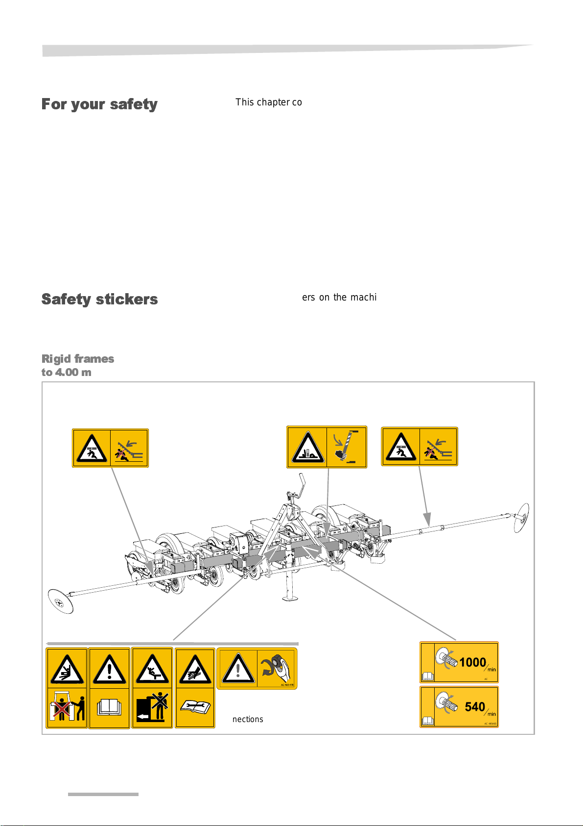
Safety stickers
Rigid frames
to 4.00 m
This chapter contains general saf ety instruct ions. Each chapter of the
operating manual contains additional specific safety instructions
which are not described here. Observe the safety instructions:
• in the interest of your own safety,
• in the interest of the safety of others,
• to ensure the safety of the machine
Numerous risks can result from handling agricultural machines in the
wrong way . The refore , alway s work wi th sp eci al car e and never under
pressure.
The employer should:
Inform personnel working with the machine of these safety instructions at regular intervals and according to statutory regul ations.
There are stickers on the machine that serve to ensure your safety.
The stickers must not be removed. If stick ers become il legible or have
peeled off, n ew stickers can be order ed and att ached in the appropri ate places
AC 495463
For machines with hydraulic
connections
6
AC 495465
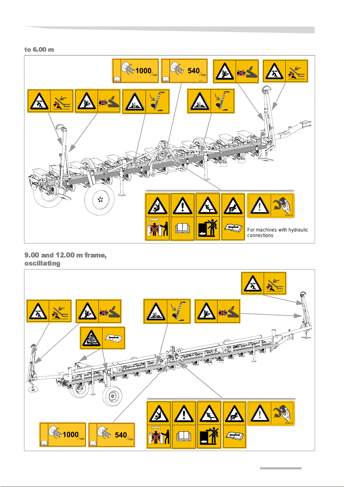
to 6.00 m
Safety
AC 495465AC 495463
9.00 and 12.00 m frame,
oscillating
For machines with hydraulic
connections
AC 495463
AC 495465
For machines with hydraulic
connections
7
Safety
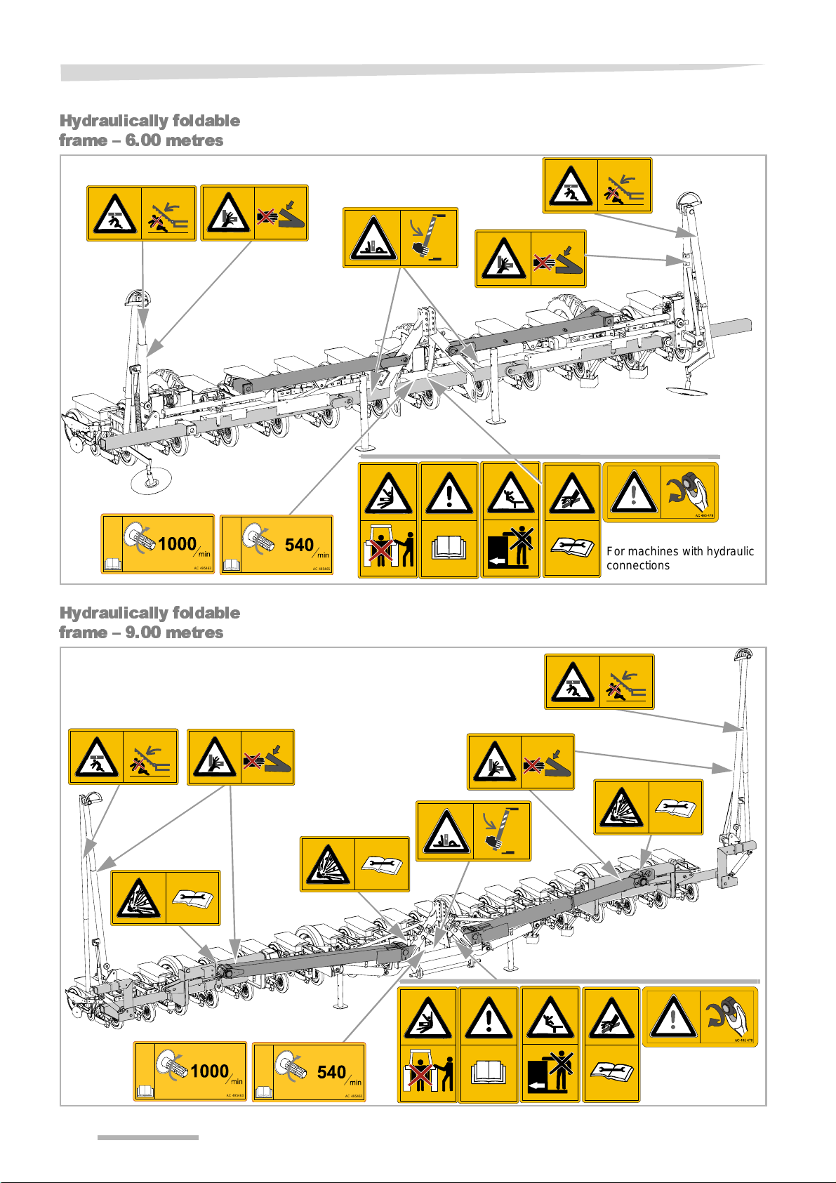
Hydraulically foldable
frame – 6.00 metres
AC 495463
Hydraulically foldable
frame – 9.00 metres
AC 495465
For machines with hydraulic
connections
AC 495463
AC 495465
8
Safety
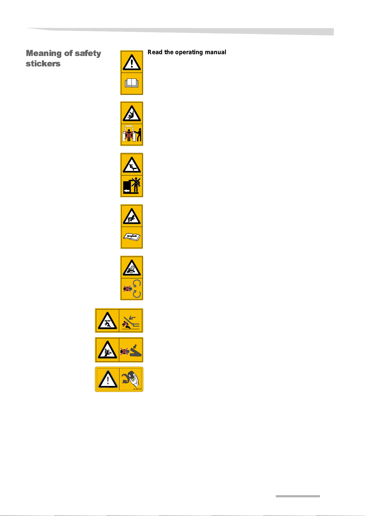
Meaning of safety
stickers
Read the operating manual carefully and follow the instructions
Initial operation of the machine must not take place before the operating manual has been read and understood. This particularly applies
to safety instructions.
Do not stand between the tractor and the machine
St anding bet ween the t ractor and the machi ne is es pecially p rohi bite d
during coupling and uncoupling and when the motor is running. The
tractor must be additionally immobili sed.
Riding on the machine is strictly prohibited
Do not transport people or objects on the machine. Riding on the machine is hazardous and strictly prohibited.
Proceed with great care in the event of leaking hydraulic fluid
Observe the corresponding safet y instruct ion s in the operating manual.
Never remove the guards
Never open or remove the guards while the engine is running. Never
operate the machine without guards.
Stay clear of the slewing range
There is an acute risk of injury in the slewing range due to swivelling
or folding machine components.
Risk of crushing
Avoid the danger area. Gaps between components may become
smaller or disappear completely.
Retighten screws
After the first opera ting hours al l scr ew must b e check ed and ret ightened, if needed. Vibrations might have loosened the screws.
9

Safety
Caution, danger of explosion
The accumulator contains pressurised gas and oil. Disassembly and
repair work must only be carried out by qualified specialists.
Caution, risk of tipping
The machine or part s thereof might topp le over . Attach the safet y supports before you stand in the danger ar ea. To uncouple, use the strut s
provided and position on a firm surface.
Check the rotational speed of the PTO stub shaft
Connect the PTO shaf t to a P TO stub s haft with t he required r otati onal
speed. Always switch off the PT O st ub shaft when working on the ma-
AC 495463
chine.
AC 495465
10

Safety
Who i s a llo w e d to
operate the ma-
chine?
Couplin g
Only qualified personnel
Only qualified persons who have been informed of the dangers associated with handling the machine are permitted to operate, service or
repair the machine. As a rule, such persons are trained and experienced in agricultural work or have bee n tho roughly train ed in a si milar
fashion.
Increased risk of injury
When coupling the machine to the tractor, there is an increased risk of
injury. Therefore:
• Secure the tractor in such a way that it cannot roll for wards or back-
wards
• The tractor and machine must belong to the same category
• Never stand between the tractor and the machine during coupling
• Actuate the three-point power l if t system slowly and carefully
Nonobservance can lead to serious or fatal injury.
Only connect electric wires or cables after mounting the at tachment
The electrical supply must not be connected to t he tractor when mounting the lighting equipment. Short circuits and damage to the electronics are possible.
Only connect hydraulics at zero pressure
Only connect the hydraul ic hose s to the tr actor hy drau lic sy stem if th e
tractor and machine hydraulic system is depressurised. A hydraulic
system which is under pr essure can cause unforeseen movement s on
the machine.
High pressures in the hydraulic system
The hydraulic syst em is under hi gh pressure. Regul arly check a ll lines,
tubes and screwed connecti ons for leaks and ext erna lly visi ble damage. Only use suitable agent s when looking for leaks. Elim inat e damage immediately. Escaping fluid may result in injuries and fires. Seek
medical attention immediately if injur ies occur .
Colour-coded hydraulic hoses
To prevent operating errors, plug sockets and plugs for hydrau lic connections between the tractor and the machine must be identified by
different colours . Incorrectly connec ted hydraulic tube s can initiate unforeseen movements on the machine.
11
Safety
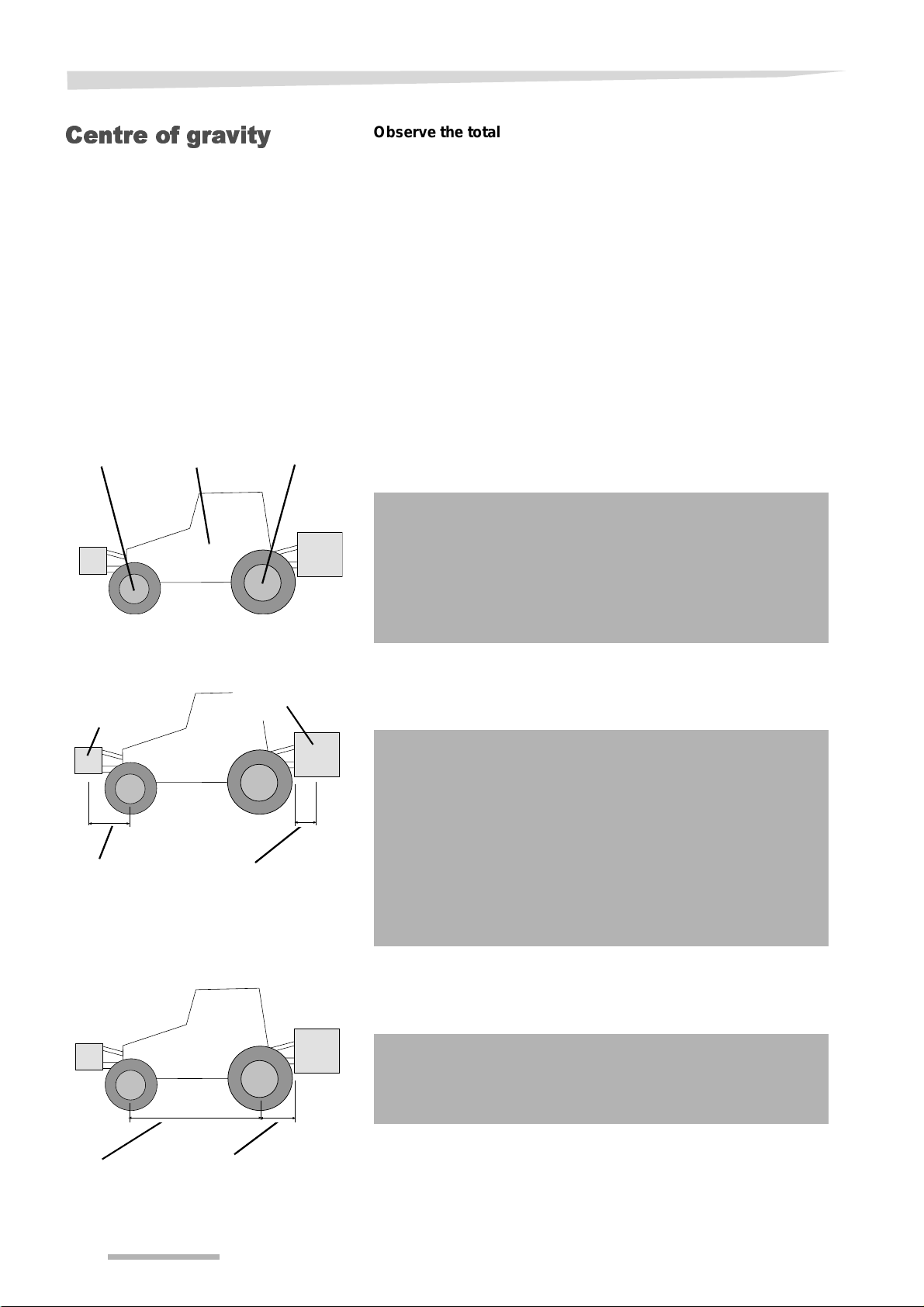
Centre of gravity
(B)
Front axle
load
(A)
Empty
weight
(C)
Rear axle
load
Observe the total weight, axle loads, tyre load-bearing capacity
and minimum ballast specifications
The front or rear at tachment of machines must not cause the tractor's
permissible total weight, its permissible axle load or its tyre load-bearing capacity to be exceeded. In order for steering capability to be
maintained, the front axle must bear at least 20 % of the t ractor's empty weight.
By investing some effort in making t he calculations i t is possible to determine the:
• Gross weight
• Axle load
• Tyre load-bearing capacity and
• Minimum ballast
The following data is required to make this cal culation:
Data from the tractor's operating manual:
• (A) Empty weight
• (B) Front axle load
• (C) Rear axle load
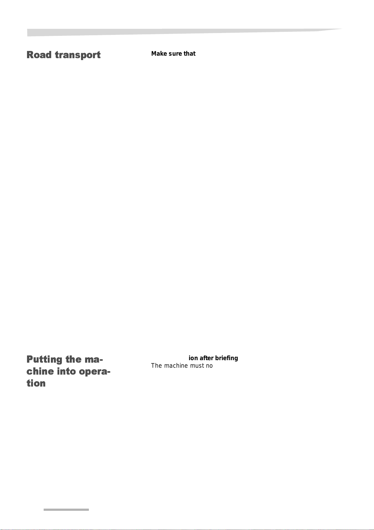
(E)
Total weight of
front attachment
(F)
Distance:
between centre of
gravity of front attachment and
middl e of f ro nt ax le
(D)
Total weight
rear attachment
(G)
Distance:
between lower link ball
midpoint and centre of gravity of rear attachment
Please take into consideration, for example, the weight of water in
the tyres, accessories, etc.
Data from this operating manual:
• (D) Total weight of the machine (rear attachment); the suppor-
ting load with the equipment attached
• (E) Total weight of the machine (front attac hme nt)
• (F) Distance between the machine's centre of gravity (front at-
tachment) and the centre of the front axle
• (G) Distance bet ween lower link b all midpoint and the machine's
centre of gravity (rear attachment). With machines attached,
G=0.
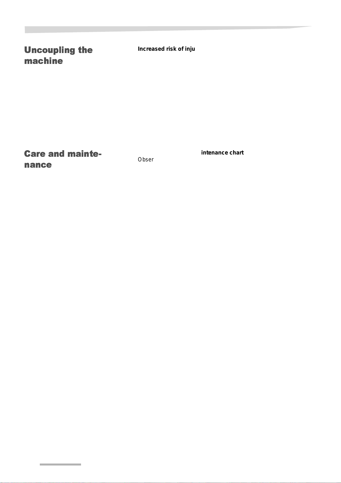
Data which you can determine through measurement:
• (H) The tractor's wheel base
(H)
Wheel base
12
• (I) Distance between the rear axl e midpoi nt and the lower link
ball midpoint
(I)
Distance:
between middle of rear
axle and lower link ball
midpoint

Safety
Calculation
Front ballast
Rear ballast
Front axle load
Gross weight
Rear axle load
The measured values can now be inserted into the formulae.
Calculation of front ballast
for machines attached at rear.
DIG
Front ballast in kg =
Calculation of rear ballast
for machines attached at front.
Rear ballast in kg =
Calculation of the actual front axle load
Front axle load in kg =
Calculation of act u a l to tal weight
Total weight =
Calculation of the actual rear axle load
Rear axle load in kg = actual total weight - actual front axle load
-------------------------------------------------------------------------------------------
EF×
------------------------------------------------------------------------------------
EFH) BH) DIG)+(×–×(++(×
-------------------------------------------------------------------------------------- -
EAD++
)+(× BH) 02 A H)××,(+×(–
FH+
) C( H) 045 A H)××,(+×–
HIG++
H
Tyre lo ad rating
Summary
Information about the tyre load-bearing capacity of the front and rear
wheels can be found in the tyre manufacturer's details.
• The front tyre load- bearing capacity for t wo wheels is equal to t wice
the permissible tyre load-bearing capacity of a single front wheel.
• The rear tyre load-bear ing capacity for two wheel s is equal to twice
the permissible tyre load-bearing capacity of a single rear wheel.
Check if the following conditions are met:
• The actual values for the rear axle load must be less than the per-
missible values given in the tract or's operating manual.
• The tyre load-bearing capaci ty must be great er than the values for
the rear axle load given in the operating manual.
• The actual total weight must be less than the permissi ble total
weight given in the tractor's operating manual.
If these conditions are not met, the machine must not be attached to
this tractor.
If you have a sufficiently large weigh-br idge, you can determine the total weight and the rear axle load by weighing.
13
Safety
Road transport
Make sure that the condition of the machine conforms to traffic
regulations
The machine must conform to current traffic regulations if you intend
to drive it on public roads. These include, f o r example:
• Lights, warning equipment and protective equipment are installed
• The permissible transport width and wei ght, axle loads, tyre load-
bearing capacity and total weights are observed
The driver and owner of the vehicle are liable if traffic regulations are
not observed.
Close the ball valves
If there are ball valves on the hydraulic lines or chassis cylinders, you
must close them prior to road transport. The accidental actuation of
control valves o n the tractor might otherwi se cause movements on the
machine. This can result in damage to the machine or accidents.
Check remote cord for the quick release coupling
Remote cords must hang loose and must not, when in their lowered
position, release the coup lings of their own accord. Coup led machines
might otherwise come loose from the three-point linkage of their own
accord.
Riding on the machine is strictly prohibited
Do not transport people or objects on the machine. Riding on the machine is hazardous and strictly prohibited.
Putting the ma-
chine into opera-
tion
Note the altered driving and braking performance
Driving and braking performance are altered when the machine is attached to the tractor. Take the width and balancing weight of the machine into consideration, especially when cornering. A driving style
which not adjusted to the road conditions can l ead to acci dents.
Moderate your speed
Always adjust your driving speed to the road conditions. If conditions
are poor and your speed is too high, extremely high forces can arise
that place a major load on the tractor and machine and might overstress them. T ravelling at an inappropriate speed can result in machine damage and accidents.
Initial operation after briefing
The machine must not be put into operation until the user has been
given proper initial instruction by an employee of the dealer, a factory
representative, or an employee of the manufacturer. Commissioning
without instruction can lead to damage to the machine due to false
operation or accidents can happen.
Ensure that the machine is in perfect working condition
Do not operate the machine unless it is in perfect working condition.
Check all important components and replace any defective components before starting the machine. Defect components can cause damage to equipment and injury to persons.
14

Safety
Do not remove the protective equipment
Protective equipment must not be removed or by-passed. Check all
protective equipment before start ing the machine. Unprotected machine components can cause severe or fatal accidents.
Checking tyre pressures
Check tyre pressure regularly. If the tyre pressure is too high or too
low, this can reduce the service life of the tyre and result in undesirable work results. Accidents might occur during road transport.
Riding on the machine is strictly prohibited
Do not transport people or objects on the machine. Riding on the machine is hazardous and strictly prohibited.
Height of machine and overhead power lines
If a height of 4.00 m is exceeded when folding the machine in and out,
the machine must not be folded in the vicinity of conducting overhead
power lines! Danger of electrocution! Should the machine come into
contact with an overhead power line:
• Do not attempt to climb out of the tractor cabin
• Do not touch any metal parts on the tractor
• Do not create any conductive contact with the ground
• Warn all persons in the area not to app roac h the tractor or the ma-
chine
• Wait for help from professional emergency service personnel as
power in the overhead line must first be switched off
Never climb onto the machine if it is beneath con ducting overh ead power lines. The voltage can jump even if the lines are not actually touching the machine.
Make sure the immediate vicinity is clear
Before starting up, folding out the machine, and using it, check the
vicinity of the machine. Mak e sure the oper ator has an adequat e view
of the work area. Do not beg in work unt il th e immediate vicinity is cleared of any persons or objects. Any use of the machine without verification of the situation around it can lead to accidents.
Retighten all nuts, bolts and screws
Nuts, bolts and screws should be checked at regular intervals and
tightened if necessary. Screws can come loose unnoticed while operating. Damage can occur to the machine or injury to persons.
What to do in the event of a malfunction
In the event of a malfunction, shut down and secure the machine immediately. The malfunction may be eliminated immediately, or your
dealer must be assigned the task. Further operation of the machine
can lead to damage to the machine or injury to persons.
15
Safety
Uncoupling the machine
Care and m ai nte-
nance
Increased risk of injury
There is an increased risk of injury when uncoupling the
machine from the tractor. Therefore:
• Secure the tractor in such a way that it cannot roll for wards or back-
wards
• Never stand between the tractor and the machine during uncou-
pling
• Actuate the three-point power l if t system slowly and carefully
• Make sure the machine is standing on a secure and level surface
• Only disconnect the hydraulic hoses if there is no pressure in the
tractor and machine hydraulic system
Nonobservance can lead to serious or fatal injury.
Follow the care and maintenance chart
Observe prescribed interval s for maintenance chec ks and insp ections
specified in the operat ing manual . No nobservanc e of the time peri ods
can lead to damage to the machine, poor quality of work or accident s.
Only use OEM replacement parts (original equipment manufacturers)
Many components have special ch aracteris tics whic h are essent ial for
the machine's stability and correct function. Only accessories and
spare parts supplied by the manufacturer have been tested and approved. Using other pr oduct s may le ad to mal functions or impa ir safety. The use of non-OEM spare parts renders the manufacturer's guarantee null and void and frees the manufacturer from all liability.
When performing care and maintenance work:
• Switch off the tractor's power take-off shaft
• Depressurise the hydraulic system
• Whenever possible, uncouple the tractor
• Make sure the machine is standing securely. Provide additional
support as required
• Do not use parts of the machi ne as c lim bing ai ds; u se on ly spec ial
and safe means of ascent
• Secure the tractor so that it cannot rol l forwards or backwards
• Never reach into the V-belt while it is moving
It is only possible to guarantee work safety during care or maintenance work through observing these regulations.
Turn off the electrical supply
Prior to carrying out work on the electrical system, disconnect it from
the power supply . Equipment under electrical power can cause damage to equipment and injury to persons.
16

Safety
Replace hydraulic hoses
Replace hydraulic tubes every three years. Hydraulic hoses can age
without any externally vi sible damage. Defect hy drauli c lines can lead
to severe or fatal injuries.
Caution when cleaning with a high-pressure cleaner
The machine can be cleaned using either water or a steam jet. Only
use low pressure to clean bearings, fans, signal distribution boxes,
plastic part s and hydraulic tubes. Excessi vely high pressures can cause damage to these parts.
Prior to welding work, disconnect the battery and generator
Prior to carrying out electrical welding work on the attached machine,
disconnect the tractor's battery and generator. This prevents damage
to the electrical syst em .
Tighten the screw connections
All screw connections r eleased d uri ng mainte nance and rep air oper ations must now be retightened. Loo se threaded connecti ons can undo
without you noticing during your work. As a result, machine parts can
fall off. Severe injury to persons or damage to equipment can result.
Further regulati-
ons
Observe the regulations
In addition to these safety instructions, observe the following:
• Accident-prevention regulations
• Generally recognised safety regulations, occupational heal th re-
quirements and road traffic r egulations
• Instructions given in this oper ati ng manual
• Operation, maintenance, and repair regulations
17
Getting to know the machine
Range of applica-
tion of the ma-
chine
Proper u s e
This section contains general information on your machine and information on:
Getting to know the mach ine
• Range of application
• Proper use
• Definitions
• Characteristics
• Designation of the assemblies, and
• Technical specifications
The Miniair Nova is a precision seed drill for seeding after seedbed
preparation. It i s for normal use i n agriculture. V er satile equipment options allow the seeding of round, calibrated seed. The prerequisite is
always a soil condition that allows cultivation and seeding. The level
of wetness or dr yness, f or exampl e, ca n make se eding t he soil impossible with some soil types.
Any application other than or beyond this, e.g. as a means of transport, for stump pulling or to transfer power t o other objec ts i s considered improper use. The manufacturer and dealer are not liable for damage caused by improper use. The risk is borne solely by the user
Definitions
Seeding after ploug-
hing
Seeding after seed-
bed preparation
Mulch seeding
Direct seeding
There are different in terpretations and definiti ons for some agr onomic
terms. The terms used in this opera ting manual are defined as foll ows.
Seeding after completion of turning the soil with the plough.
Seeding after completion of seedbed prepar ation or secon dary prep aration after turning the soil. The purpose of seedbed preparation is to
prepare the top soil layer f or seeding. By working at a const ant depth,
clods are crushed, the soil surface levelled and the ground below the
seed deposit is recompacted due to the soil contact required.
Seeding after completion of mixing the soil. The soil must be worked
deeper than the required deposit depth.
Seeding without working the soil. Residue from the previous crop is
chaffed or in a condition that enabl es dir ect seeding.
18

Getting to know the machine
Characteristics of the machine
Perfect combination
Thanks to specially harde ned mate rial combined wi th an opt imum design and high manufacturing quality, you acquire a reliable machine
for seeding. It is easy t o handle and featur es low-maintenance mechanics.
Exact depth adjustment and guidance
All sowing units can be adjusted exact ly to the des ired depth. The deposit depth can be adjusted via the front press wheels. The pre-running press wheels allow in combination with parallelogram construction of the sowing units a precise depth guidance.
Seed spacing and seed deposit
Even without tools, the seed spacing can be adjusted easily either
electronically or using a shift gear. The optoelectronics of the machinery is responsible for the monitoring of the grain deposit (accessory). An inter mediate pre ss wheel beds the s eed in an optimum manner in the moisture-c onducting soi l layer . A seed coverer cove rs it wit h
loose earth and a press wheel firms up the ground which means that
it is better protected against mud formation.
19
Getting to know the machine
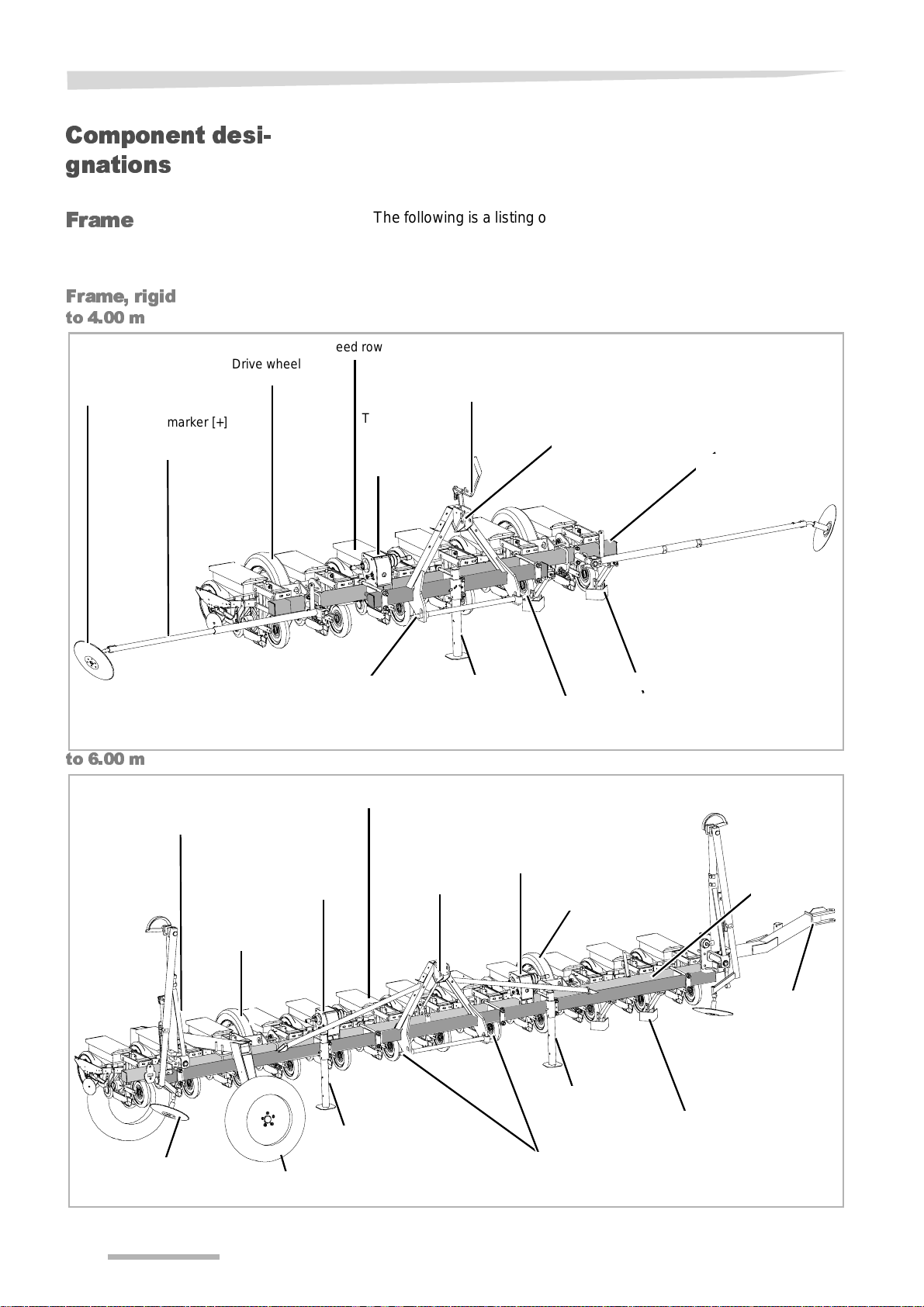
Component desi-
gnations
Frame
Frame, rigid
to 4.00 m
Track marker
disc [+]
Track marker [+]
Drive wheel
The following is a list ing of the most important assemblies in the frame
as an overview. The assemblies for the sowing units can be found
from page 23.
.
Seed row
Switchover lever for
the track marker
Transmission
(for mechanical
machines)
Attach m e nt po i nt
for the primary
top link
Frame
to 6.00 m
Track marker [+]
Drive wheel
Track marker
disc [+]
Attachment
point for the lower link
.
Seed row
Attachment
Transmission
(for mechanical machines)
Drawbar
pipe
Transportation wheel of the
lengthways transport attachment
point for the
primary top
link
Drawbar
pipe
Transmission
(for mechanical machines)
Attachment
point for the lower link
Attachment
point for the lower link
Drive wheel
Drawbar
pipe
Clod deflector [+]
Frame
Drawbar on
the lengthways
transport attachment
Clod deflector [+]
20
Getting to know the machine
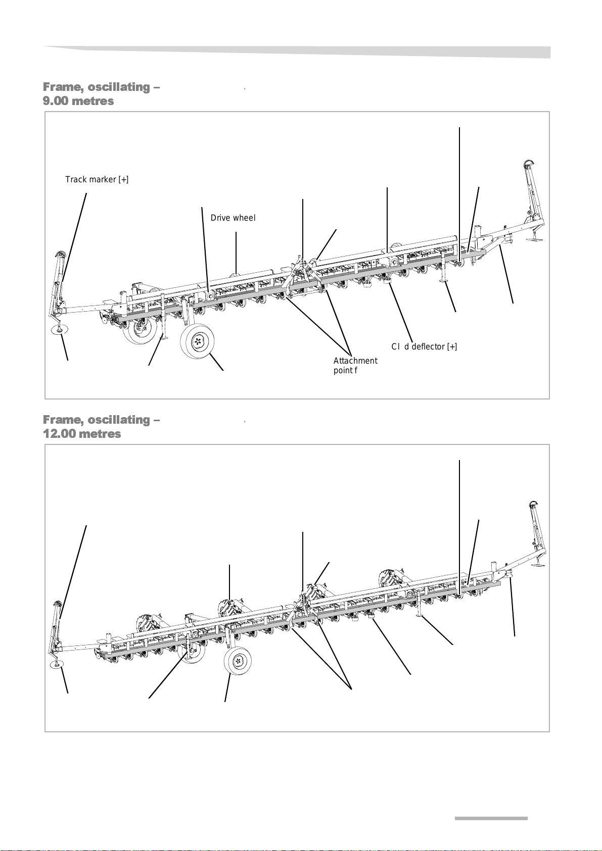
Frame, oscillating –
9.00 metres
Track marke r [+]
Track marker
disc [+]
Drawbar
pipe
.
Transmission
(for mechanical machines)
Drive wheel
Transportation wheel of the
lengthways transport attach-
Attachment point
for the primary
top link
Drive wheel
Transmission
(for mechanical machines)
Attachment
point for the lower link
Seed row
Drawbar
pipe
Clod deflector [+]
Frame
Drawbar on
the lengthways
transport at-
Frame, oscillating –
12.00 metres
Track marke r [+]
Track marker
disc [+]
Drawbar
pipe
.
Attachment point for
the primary top link
Drive wheel
Transportation wheel of the
lengthways transport attachment
Drive wheel
Attachment
point for the lower link
Seed row
Drawbar
pipe
Clod deflector [+]
Frame
Drawbar on
the lengthways
transport attachment
21
Getting to know the machine
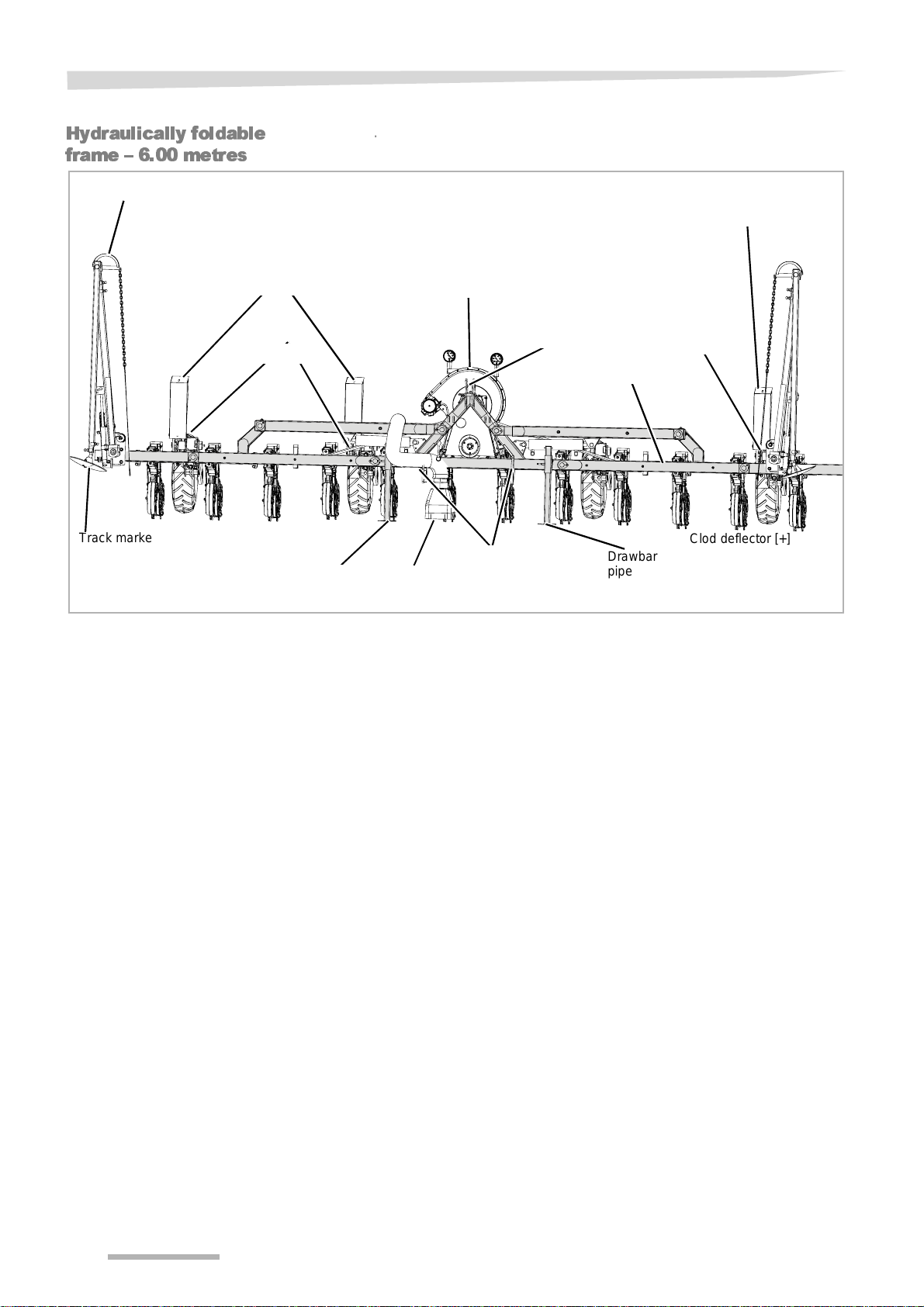
Hydraulically foldable
frame – 6.00 metres
Track marker [+]
Transmission
(for mechanical machines)
Drive wheel
Track marke r
disc [+]
Drawbar
pipe
.
Clean-Air
[+]
Fan
Attachment
point for the lower link
Attachment point for
the primary top link
Frame
Drawbar
pipe
Transmission
(for mechanical machines)
Drive wheel
Clod deflector [+]
22
Getting to know the machine
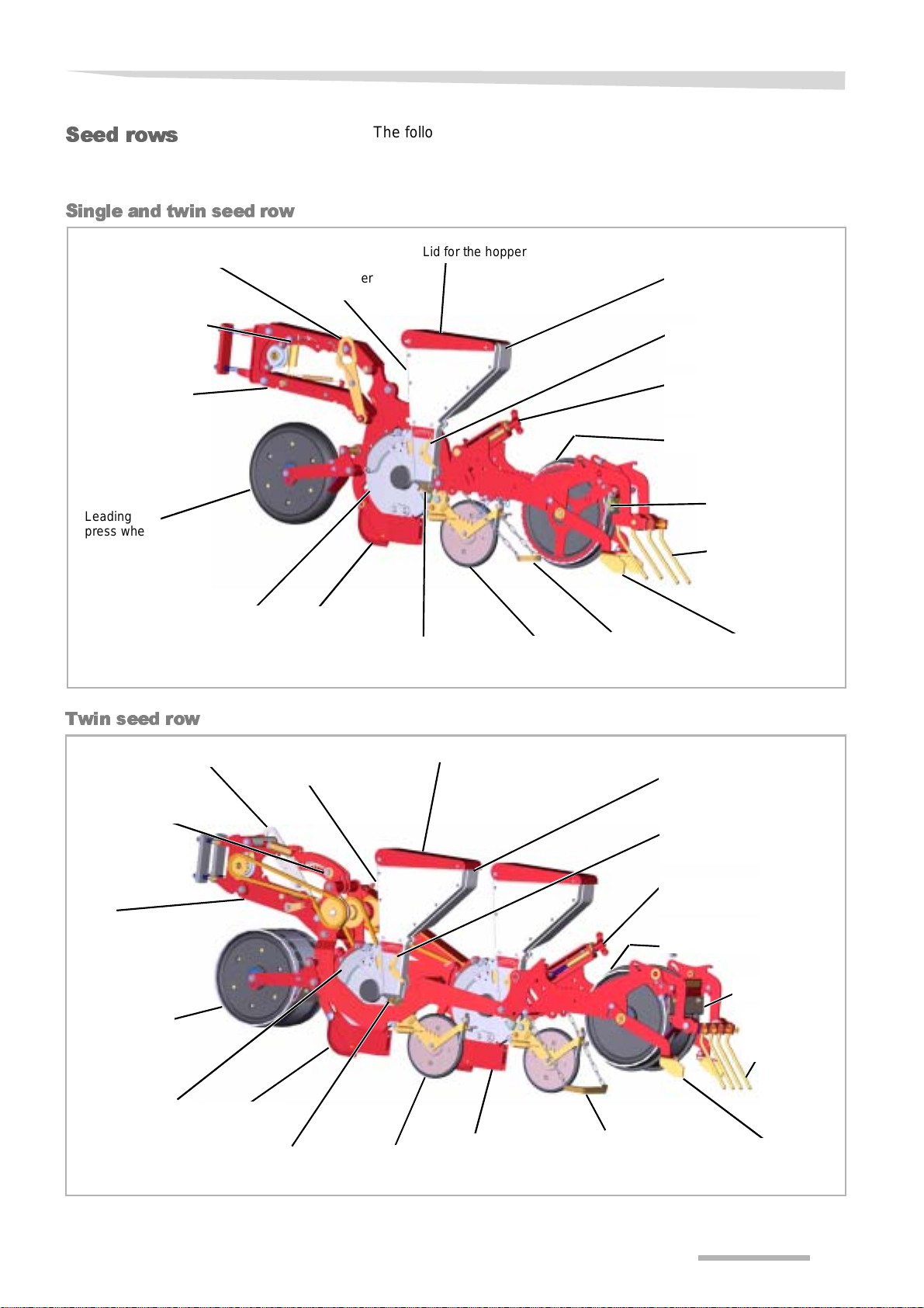
Seed rows
Single and twin seed row
Lift assembly
Adjust the load or
load-relief
Parallelogram
Leading
press wheel
Seed hopper
The following is a listing of the most important assemblies for the sowing units.
The assemblies for the frame can be found from page 20.
Lid for the hopper
Grip for opening the
seed hopper
Adjust the scraper on
the seeding heart
Adjusting working depth
Press wheel,
here the Farmflex
Scraper
Coverer,
here the finger coverer
Twin seed row
Lift assembly
Adjust the load or
load-relief
Parallelogram
Leading
press wheel
Seeding
heart
Coulter tip(s)
Seed hopper
Hopper emptying
flap
Lid for the hopper
Intermediate
press wheel [+]
Towing coverer
[+]
Grip for opening the
seed hopper
Adjust the scraper on
the seeding heart
Adjusting working depth
Press wheel,
here the Farmflex
Blade coverer [+]
Scraper
Coverer,
here the finger
coverer
Seeding
heart
Share wedge
Hopper emptying
flap
Intermediate
press wheel [+]
Second seed
row
Towing coverer
[+]
Blade coverer [+]
23
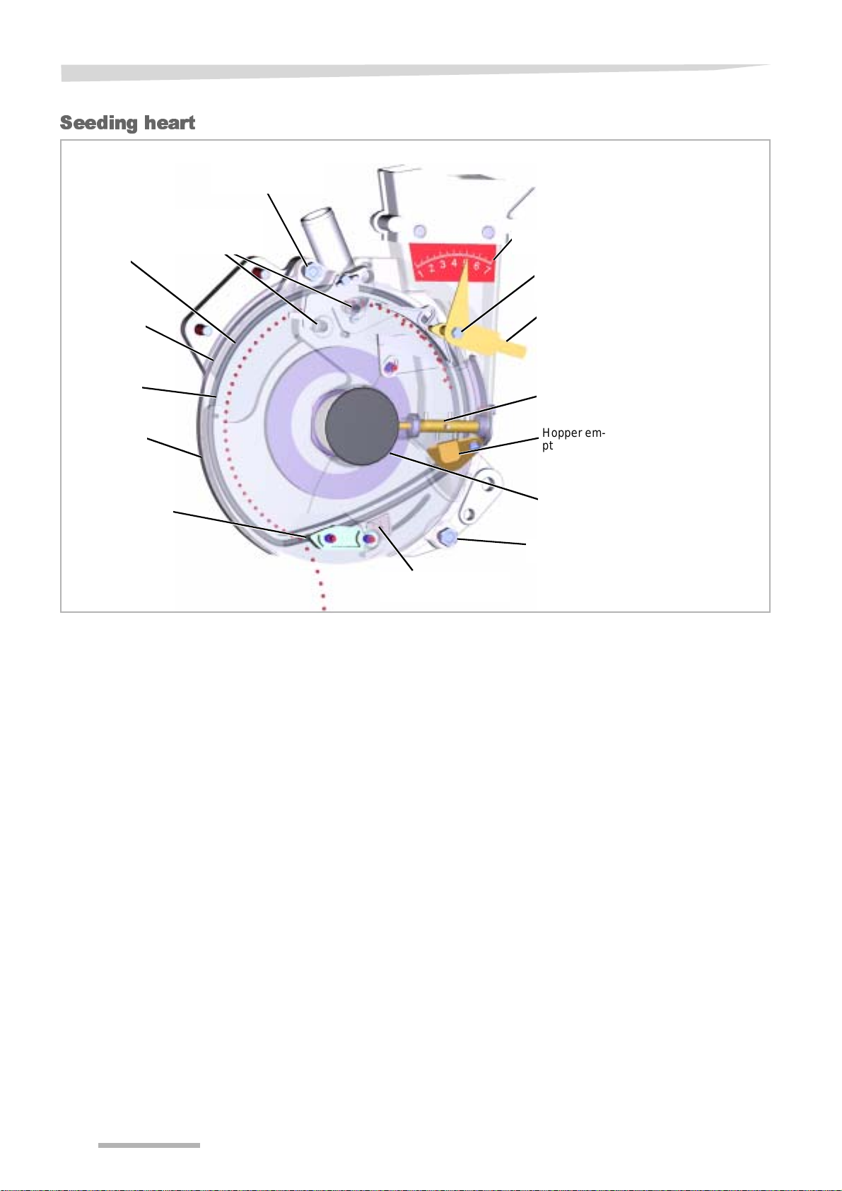
Getting to know the machine
Seeding heart
Screw for the lid of
the seeding heart
Additional scraper for
O-ring
Window
special seed [+]
Orientation scale
Sealed adjustment
screw
Scraper, adjustable to suit seed
Seed disc
Lid of the seeding heart
Fixed scraper
Cleaning jet
Agitator shaft
Hopper emptying flap
Cover cap concealing drive for agitator shaft
Nut for the lid of the seeding heart
24

Technical specifi-
cations
Frame
Getting to know the machine
Height (m) Width (m) Depth
(m)
Working
position
2.00-4.00 m 2.25-2.50 2.25-2.50 2.55-2.80 2.55-2.80 1.80 see model pla-
4.50-6.50 m 2.70-3.00 2.70-3.00 6.00 2.65-2.90 1.80 see model pla-
9.00 metres 2.40 3.20 9.00 2.70 2.70 see model pla-
12.00 metres 2. 40 3.20 12.00 2.95 2.70 see model pla-
6.00 m PH 1.80-2.20 2.90-3.20 6.10 2.80-3.20 1.70 see model pla-
Transport position
Frame, rigid
Frame, oscillating
Hydraulically foldable frame (PH)
Working
position
Transport position
Weight (kg)
te
te
te
te
te
Lengthways transport attachment, mountable
Draw bar 25
per transport wheel 40
Equal iser bar 30
Lengthways transport attachment, hydraulically foldable
Draw bar 210
per transport wheel 40
Equal iser bar 30
25

Getting to know the machine
Seed row
Seed hopper
Volume (l) 4
Filling hei g ht
• minimum up to the socket
• maximum roughly 1 cm from the edge
Weights of the sowing unit (kg) without seed
Single / twin seed row 29.5 / 32.0
Twin seed row 50.0
Tool weights (kg)
Finger coverer 1.7
Adjustable coverer 1.1
of the hopper
Towing coverer 0.3
Intermediate press wheel with rubber mount 1.0
Intermediate press wheel with stainless-steel ring 1.2
Press wheel with stainless -steel ring 4.8
26

Others
Tractor
Air pressure of tyres (bar)
Getting to know the machine
Minimum tractive power (kW)
• 2.00 - 4.00 m, rigid from 30
• 4.50 - 6.50 m, rigid from 50
• 9.00 metres and 12.00 metres from 65
• 6.00 m PH from 65
Transport wheel s
• 7.00 - 12 2.0
• 10.0 / 75 - 15.3 4.0
Drive wheels
• 7.00 - 12 1.5
Granule distributor [+]
Hopper volume (l) 33
Number of overflow outlets 2 or 3
Filling height
• minimum (l) 0.3
• maximum roughly 1 cm from the edge of the
Number of sowing units 6 - 18
Control system and the electrohydraul ics
Power supply (V) 12
Fuse (A) 16
Type of protection
for all electrical systems IP 65
hopper
27

Delivery and assembly
Delivery and assembly
Check scope of supply
The machine is delivered compl etely assembled. I f part s of the machi ne have not been assembled, please contact your dealer.
Do not assemble the machine yourself
Do not do assembly work yourself since prerequisites for an orderly
condition of the machine are :
• observance of a sequence of worksteps
• observation of tolerances and torques
• safe handling of the electronics
If parts are missing or have been damaged during transportation,
please submit a complaint immediately to your dealer, importer or the
manufacturer.
28
Coupling the machinery
Couplin g the m a-
chine
Increased risk of injury
When coupling the machine to the tractor, there is an increased risk of
injury. Therefore:
Coupling the machinery
• Secure the tractor in such a way that it cannot roll for wards or back-
wards
• The tractor and machine must belong to the same category
• Never stand between the tractor and the machine during coupling
• Actuate the three-point power l if t system slowly and carefully
Nonobservance can lead to serious or fatal injury.
The machine is fact ory-equipp ed for mount ing with a three-poi nt li nkage.
> Slide suitable catch pan s on the lower link arms of the machine for
the tractor and secure with linchpins
> Couple the machine and raise slightly by means of the lower links
> Slide up support legs and secure with bolt. Secure bolt wit h cotter
pin.
> Adjust the top link so that the frame is parallel to the ground in the
working position and the three-point block is vertical
> Adjust the lower li nk so t hat the machi ne has littl e play to the left or
right
Never adjust the depth of the machine via the lower link, but rather at
each individual sowing unit.
Connections
Electrics
Increased risk of injury
When coupling the machine to the tractor, there is an increased
risk of injury. Therefore:
• Secure the tractor in such a way that it cannot roll for wards or back-
wards
• Switch off the tractor engine
After coupling, make the followi ng connections:
• Electrics
• Hydraulics
If present, connect the el ectri cal cabl es for th e foll owing to the tracto r:
• The folding of the PH frame
• The folding of the electrohydraulic track markers
• The machine's electronic control system
• The lighting equipment on the machine
> Check all connections to make sure they are working properly.
29

Coupling the machinery
Hydraulics
Hydraulic connection at zero pressure only
Only connect the hydraul ic hose s to the tr actor hy drau lic sy stem if th e
tractor and machine hydraulic system is depressurised. A hydraulic
system which is under pr essure can cause unforeseen movement s on
the machine.
Avoid mixtures of different oils
If the machine is used with different tr actors, incompatible types of oil
may become mixed. Such a mixture of incompatible oils can result in
the destruction of tractor components.
Check tubes and couplings
Check all hydraulic tubes for damage before connecting them up.
Check for firm seating of all hydraulic couplings once connected. Defect hydraulic tubes or poorly seated hydraulic couplings can initiate
unforeseen movements on the machine or lead to acci dents.
Securing the control system
Secure the control systems on the tractor in the transport position
against unintended actuation. Unintended actuation of a control system can trigger un foreseen movements on t he machine or lead t o injury to persons.
30
 Loading...