

ES/LS
Operator‘s manual
Original operator‘s manual
Edition 06.2015
Date of printing 06.2015
Language EN
Machine number
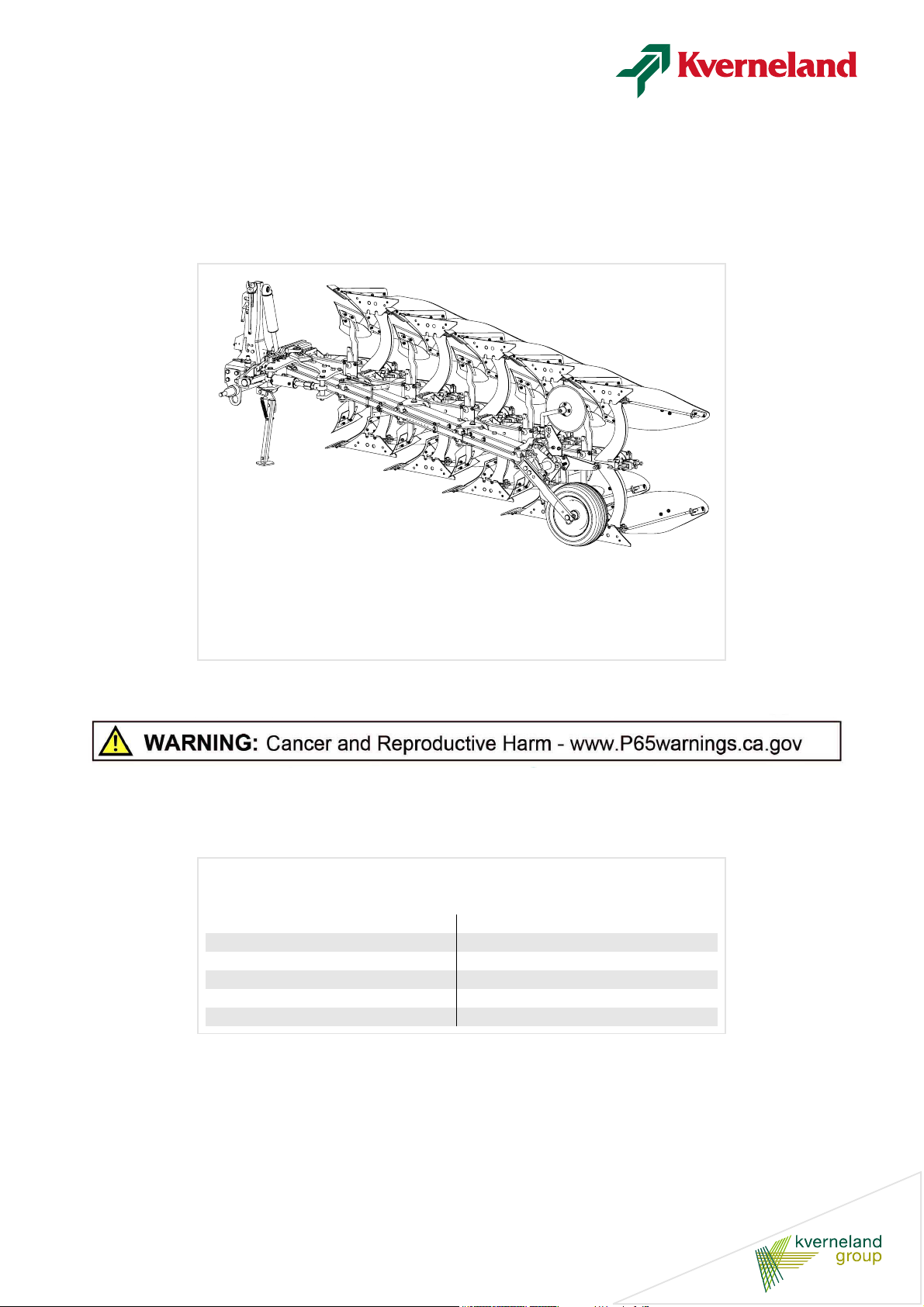
Model ES/LS
Document number A133309940.EN

Machine identification
In order for your dealer to assist you as efficiently as possible, you will need to provide some information about
your machine. Please enter the details here.
Designation
Machine ID
Address of
supplier
ES/LS
Address of
manufacturer
Kverneland Group Operations Norway AS
Plogfabrikkvegen 1
4353 Klepp Stasjon
Norway
Tel. +47 5142 9000
www.kvernelandgroup.com
Copyright by Kverneland Group Operations Norway AS. Reproduction, transfer to other media, translation or the use of extracts or parts of this
manual without the explicit permission of Kverneland, is not permitted. All rights reserved. The contents of this operator’s manual are subject to
change without notice. The right to technical revision is reserved.

Table of contents
Preface ....................................................... 4
Target group for this operator‘s manual 4
Demonstration and training 4
Symbols used 4
Terminology used 5
Safety ......................................................... 6
DANGER, WARNING and CAUTION
labels 7
General safety information 10
Getting to know the plow ......................... 15
Proper use 15
Features 15
Components 16
Technical specifications 18
Cross shaft 19
Tire pressure 19
Information plate 20
Optional equipment .................................. 21
Preparation for use ................................... 27
Tractor 27
Remove paint 28
Connecting ................................................ 29
Coupling 29
Connection geometry 30
Clearance between the depth wheel/plow
and the ground 30
Clearance between the tractor and plow 30
Table of contents
Before maintenance 55
Maintenance table 56
Cleaning 56
Replace hoses 60
Replace worn parts 60
Replace Quick-fit points 61
Replace Knock-on® points 61
Tighten bolts and nuts 62
Check springs for correct length 63
Tire pressure 64
Set the bodies 64
Possible modifications ............................. 67
Reversing direction 67
Restrictor position 67
Spring release system [ES] 68
The position of the cross shaft 74
Parking and storage .................................. 75
Parking and storage 75
Plow with Eco-plowshare [+] 75
Storage 75
Troubleshooting ........................................ 76
Checklist .................................................... 77
Disposing of the plow ............................... 79
EU goods certificate .................................. 80
Index ........................................................... 1
Transport ................................................... 31
Safety 31
Before transport 32
Stabilize rotating cross shaft [+] 32
Put into transport position 33
Set into the plowing position 37
Set into the plowing position 39
Adjust the plow ......................................... 41
Working width 41
First furrow width 43
Working depth 44
Levelling 46
Disc coulter [+] 48
Skimmer [+] 50
Trash board [+] 51
Soil packer arm [+] 51
Plowing ...................................................... 53
Safety 53
Before plowing 53
Check during plowing 53
Reversing the plow 54
Care and maintenance ............................. 55
Safety 55
3

Preface
Preface
Target group for
this operator‘s
manual
This operator‘s manual is intended for personnel concerned with the
inspection, use and maintenance of the plow. It contains all the infor-
mation needed for safe handling, use and maintenance of the plow.
For your safety
Before starting to adjust and use your plow, familiarize yourself with
this operator‘s manual. Doing so will help ensure the operator‘s safety
and the safety of any persons in the immediate area. It is very impor-
tant to read this manual carefully before using the plow and to keep it
handy. In this way, you will:
•
Avoid accidents
•
Satisfy the warranty terms and conditions
•
Ensure that you have a functional plow which works as it should do
at all times
•
Understand how to operate in different conditions.
\
WARNING
Observe the warning triangle
The warning triangle indicates important safety information and
danger. Failure to observe this safety information can result in:
•
Improper use of this machine
•
Damage to the machine,
•
Personal injury or accidents.
Demonstration
and training
Symbols used
For the employer
Every employee must be given training at regular intervals on how to
use this plow (at least once a year) in accordance with the guidelines
issued by the employer's insurance company. Untrained or unauthor-
ized individuals are not permitted to use the plow.
You are personally responsible for the safe use and maintenance of
the plow. You must ensure that you and anyone else who is going to
operate, maintain or work around the plow is familiar with the operating
and maintenance procedures and related safety information contained
in this operator‘s manual.¨
This operator‘s manual uses the following symbols and expressions:
•
Lists are bulleted
> A triangle indicates points you must follow
→ An arrow indicates cross references to other sections of the man-
ual
[+] Indicates optional equipment
4

Preface
\
In addition to these symbols, the following pictograms are used to help
you find the text sections:
TIP“Tip” indicates useful tips and advice.
The warning triangle indicates that there is a risk involved with the
work of fitting or adjustment.
Shut off the engine, set the parking brake, remove the ignition key and
secure the tractor against rolling away.
Terminology used
This operator‘s manual uses the following terminology:
•
Right hand position: viewed from the rear, the first body is located
at the right side of the plow.
•
Left hand position: viewed from the rear, the first body is placed on
the left-hand side of the plow.
•
Turning with the bodies over: when reversing, the bodies turn over
the frame, with the depth wheel positioned under the frame.
•
Turning with the bodies under: when reversing, the bodies turn un-
der the frame, with the depth wheel positioned above the frame.
5

Safety
\
California Proposition 65
\
WARNING
Engine exhaust, some of its constituents, certain machine compo-
nents and fluids, contain or emit chemicals known to the State of
California to cause cancer and birth defects or other reproductive
harm.
\
SAFETY FIRST
This symbol, the industry's "Safety Alert Symbol", is used through-
out this manual and on labels on the machine itself to warn of the
possibility of personal injury. Read these instructions carefully. It is
essential that you read the instructions and safety
regulations before you attempt to assemble or use this unit.
Safety
\
DANGER
Indicates an imminently hazardous situation which, if not avoided,
will result in death or serious injury.
\
WARNING
Indicates a potentially hazardous situation which, if not avoided,
could result in death or serious injury.
\
CAUTION
Indicates a potentially hazardous situation which, if not avoided,
could result in minor or moderate injury.
6
\
Safety
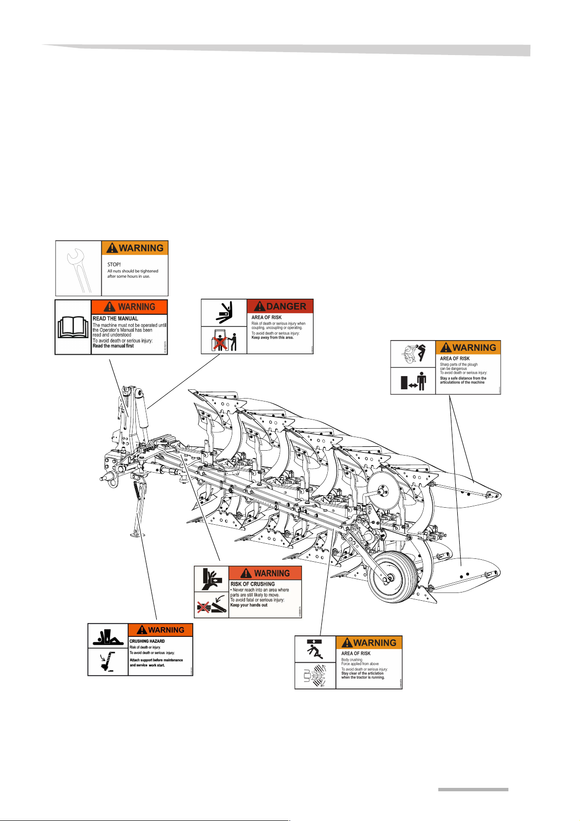
DANGER,
WARNING and
CAUTION labels
DANGER, WARNING and
CAUTION labels on the
plow
This chapter describes general safety information for this product.
Each section of this operator‘s manual also contains its own specific
safety information.
Safety decals are placed on important parts of the plow for your own
safety. Do not remove these. If they can no longer be read or start to
fall off, replace them with new spare decals (see spare-parts cata-
logue).
7

Safety
\
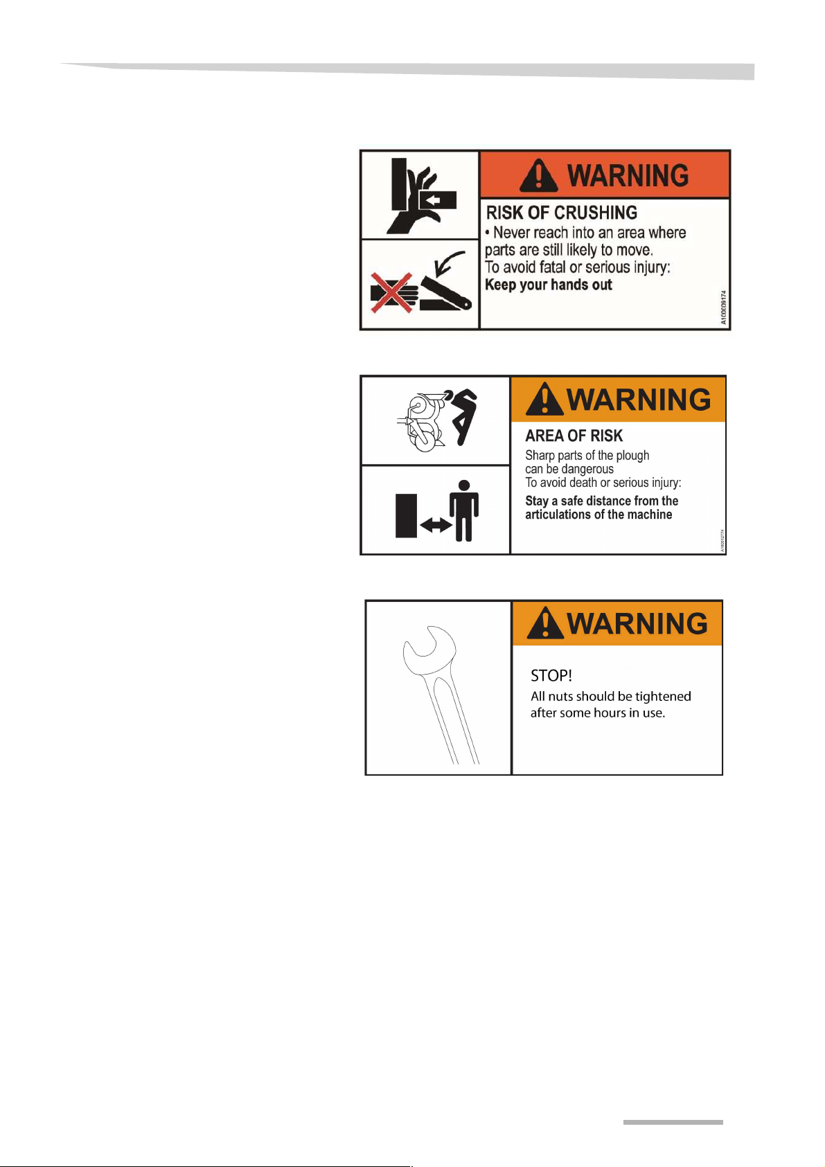
Meaning of DANGER,
WARNING and CAUTION
labels
The meaning of the safety decals is explained below.
8
\
Safety
9

Safety
General safety
information
\
Please read and ensure you understand the following general safety
information. Specific safety information is pointed out in the relevant
chapters.
For your safety
Read and ensure you understand the instructions
Before starting to operate the plow, read the operator‘s manual and
follow the instructions. Failure to follow the instructions may damage
the plow or lead to injury.
Qualified users only
The plow must not be used before the user has received the proper
training and is familiar with the function and safe use of the plow. In-
correct use of the plow can result in damage to the plow or personal
injury.
Check for technical faults
Before starting to use the plow, check that the machine is in perfect
condition. If any components are faulty, contact the dealer and ar-
range for them to be replaced. Faulty components can lead to further
faults and damage to the plow or personal injury.
Keep your distance
Do not go under or close to the plow when it is in operation or when it
is being connected to the tractor. This can result in personal injury.
Support the plow
Do not go under or close to the plow if it is not properly supported. If
the plow tips, it can damage the plow or cause personal injury.
Lower the plow
Always lower the plow when the tractor is parked. Otherwise, acciden-
tal lowering of the plow can result in damage or personal injury.
Use front weights
Adjust the tractor with sufficient front weights to ensure stability and
safe control.
Check the area
Always check the immediate area before starting to move or use the
plow. There must be no personnel in the vicinity of the plow when it is
in use.
Use the parking stand
Use the parking stand when parking the plow. If the plow is not
supported properly, it can tip over. This can result in damage to the plow
or personal injury.
10
Information for the employer
Inform all persons who work with the machine about this safety
information at regular intervals and in accordance with statutory regu-
lations.

\
Coupling
Safety
No riding on the plow
Persons or objects must never be transported on the plow. Carrying
passengers, especially children, on the plow is life threatening and
prohibited. Serious or fatal injury may be caused as a result.
Safety for children
Never assume that children will remain where you last saw them.Be
alert and shut your machine down if children come into the work area.
Never allow children to play on or operate the machine.
Increased risk of injury when coupling
There is an increased risk of injury when the plow is coupled to the
tractor. Therefore:
•
Shut off the engine, set the parking brake, remove the ignition key.
•
Secure the tractor to prevent it from rolling.
•
Do not stand between the tractor and plow when coupling
•
Lift and lower the plow slowly
An unsecured tractor can create hazardous conditions.
If this requirement is ignored, the consequence may be damage
to the machine and the potential for life-threatening injuries.
Adjust and maintain
Relieve the oil pressure – accidental movements
Relieve the oil pressure both in the tractor’s and the plow’s hydraulic
systems before connecting or disconnecting the hydraulic hoses. Otherwise, oil under pressure can result in the plow starting to move ac-
cidentally. This can result in damage to the plow or personal injury.
Check the length of the hose
Check that there is sufficient slack in the length of the hose on the plow
and between the plow and tractor. If the hoses are trapped or
stretched, this can result in the hoses becoming damaged or de-
stroyed.
Ensure the hydraulic connections are correctly coupled.
Make sure you do not cross hydraulic connections when coupling
them to the tractor. If the connections are crossed, it will cause the
plow to move unexpectedly. This may damage the plow or lead to injury.
Avoid skin contact with oil and lubricants
When handling oil or lubricants, avoid contact with the skin by using
oil-resistant gloves. Oil and lubricants can damage the skin.
Relieved oil pressure – jet streams
Before replacing hydraulic parts or performing other work on them, re-
lieve the oil pressure in the system. The oil pressure can be very high.
Jet streams due to high oil pressure can result in injury. In case of in-
jury, seek medical advice immediately.
11

Safety
\
Maintain at regular intervals
Perform maintenance on the plow at regular intervals as described in
»Care and maintenance«. Also replace worn parts as described.
Plows which are not well maintained can malfunction. This can result
in damage to the plow or personal injury.
No welding
Do not weld any part of the plow. The plow is made from reinforced
steel, and welding will greatly impair the strength of the plow. Welding
can result in the plow failing.
Retighten bolts and nuts
Retighten all the bolts and nuts on the plow at regular intervals. This
is especially important after the first few hours of use. Loosening of
bolts and nuts can result in personal injury.
→ »Tighten bolts and nuts«, page 59.
Replace the cross shaft after 1000 km (621 miles)
On large mounted plows we recommend you to replace the cross
shaft after 1000 km (621 miles) of road transport. Road transport can
result in non-visible damage to the cross shaft.
Proper working condition
Ensure that the tractor and the machine are always in proper working
condition. Make sure that the tractor brakes work in synchronisation
with the machine. Also follow the instructions in your tractor's
operator’s manual.
Wear protective clothing
Wear protective clothing, e.g. gloves, when working with sharp parts
of the plow. In particular, parts which come into contact with the soil
can be very sharp. Careless handling can result in injury.
Spesified workwear
Do not wear loose fitting or other inappropriate clothing. Loose fitting
items of clothing may become caught in rotating parts. Wear the prop-
er protective clothing. Different environments may require special
clothing to preform the operation and maintenance of the plow. Seri-
ous or fatal injury may be caused if these guidelines are not followed.
12
Use original spare parts
Use only genuine Kverneland spare parts. Other products may
adversely affect the correct operation of the plow and safety. The
warranty will no longer be valid if parts not produced by Kverneland
are used.
Check the tire pressure
Regularly check that the tire pressure meets the requirements. Incor-
rect tire pressure can result in damage and poor performance.
→ »Tire pressure«, page 17.

\
Safety
Driving on the road
Be aware of the plow’s length
The plow is very long and swings out when turning. Avoid allowing the
rear of the plow to hit obstacles during sharp swings.
Stabilize the lower links
During all operations other than plowing, stabilize the tractor’s lower
links. This prevents the plow from unintentionally moving sideways.
Obey local state, and Federal laws when transporting
Obey all laws when driving with the plow on public roads. For
example
•
have all necessary lights installed and warning signs displayed.
•
do not exceed the maximum permitted weights, loads and
dimensions.
The user is responsible for ensuring that the plow complies with the
law when driving on public roads.
Additional markings are required for road transport in some U.S. states
and some Canadian provinces:
Marking for slow-moving vehicle – SMV
This SMV emblem shall be used on all slow moving machines when
operated or traveling on public roads.
•
On slow moving machines with design specifications of a maxi-
mum speed of 40 km/h (25 mph) or less, the SMV emblem shall be
used. Per ASABE S276.7
Adjust speed: max. 25 km/h (15 mph)
Always adjust the driving speed according to the road’s conditions, but
never drive faster than 25 km/h (15 mph). Excessive speeds can result
in too much stress on the tractor, plow and transport wheel. This can
result in damage or breakage.
Speed adjustment
In poor road conditions and at high speeds, significant forces can be
generated which subject the tractor and machine material to high or
excessive stresses. Adjust your driving speed to the road conditions.
A driving style which is not adapted to conditions can cause accidents.
Accidents with serious or fatal injuries may be caused as a result.
Unrestricted field of vision to the rear
After plow has been coupled, ensure that you have an unrestricted
view of the machine, in both its work and transport positions. Other-
wise, dangerous situations may not be detected in time, resulting in
accidents or damage.
13

Safety
Hydraulics
\
Hydraulic connection at zero pressure only
Only connect hydraulic hoses to the tractor hydraulic system if the
tractor and machine hydraulic system is at zero pressure. A pressurize
hydraulic system can trigger unforeseen movements on the machine
and can cause serious machine damage and personal injury. Serious
or fatal injury may be caused as a result.
High pressures in the hydraulic system
The hydraulic system is under high pressure. Regularly check all lines,
hoses, and coupled connections for leaks and externally visible damage. Do not use hands to search for suspected leaks. Only use suita-
ble equipment when looking for leaks. Rectify any damage imme-
diately. Fluid escaping under pressure can penetrate skin and may re-
sult in injuries and fires. Seek medical attention immediately if injuries
occur.
Replace hydraulic hoses every six years or earlier
Hydraulic hoses age without showing externally visible signs. Replace
hydraulic hoses every six years, or earlier if aging or degradation is
visible. Defective hydraulic lines can cause serious or fatal injuries.
Warranty
The warranty and manufacturer's liability will no longer be valid if the
instructions provided in the chapter on Safety are not observed, if
maintenance is inadequate or faulty, if the machine is used for pur-
poses other than those for which it was intended and if it is overstressed, or if impermissible modifications are made to the machine.
14

Getting to know the plow
Proper use
Features
This chapter provides information on the plow. It instructs you on the
correct use of the plow and the plow’s functions in addition to providing
technical information.
The intended use of this machine is for purposes of plowing. Any other
use of the plow, e.g. as for lifting or pulling operations, is deemed im-
proper use. The manufacturer and dealer are not liable for damage
caused by improper use.
Two types of beam
The ES plow is equipped with Kverneland’s automatic stone release
system. The singel leaf spring system cushions the plow body when a
hard object is impacted. Once the plow has passed the obstacle, the
body automatically reverts to the correct plow depth.
The LS plow is equipped with a shear bolt beam. On collision with a
stone or other object in the ground, the shear bolt is sheared, thus pro-
tecting against greater damage.
Variable working width
The parallel design of this plow provides for a steplessly variable work-
ing width, operated either hydraulically or mechanically. This ensures
an optimum combination of tractor, plow and soil consistency.
Getting to know the plow
Complete range of bodies
We supply a complete range of plow bodies to meet all needs. Kver-
neland’s plow bodies offer excellent plowing quality, are very durable
and require low tractive power.
Robust headstock
The plow’s headstock is designed with its centre of gravity close to the
tractor, enabling lift requirements to be as low as possible.
Complete range of optional equipment
The optional equipment for the plow comprises a wide range of depth
wheels, bodies, body attachments, skims and rear disc coulters. They
can be adapted to your needs depending on the type of soil and field
conditions.
Low-wear parts
All parts in direct contact with the soil have undergone heat treatment.
This makes them extremely resistant to wear, but also flexible enough
to withstand jolts.
The direction of reversing can be changed
The plow can be reversed with the bodies over and under the
frame.The most common use is with the bodies above the frame. This
gives the most even reversing and must be used when the integrated
packer is fitted.
A smooth reversing of the plow is achieved when the bodies are above
the frame.
There is maximum clearance with the ground at the rear end of the
plow when the bodies are underneath the frame.
15
Getting to know the plow
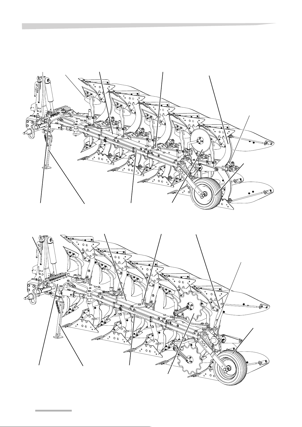
Disc coulter
Parking stand
Main frame
Automatic beam
Front piece
Beam bracket
Parallel rod
Skimmer
Headstock
Spring
Depth
wheel
Front piece
Parking stand
Main frame
Shear bolt beam
Front piece
Beam bracket
Parallel rod
Disc coulter
Headstock
Depth wheel
Shear bolt
Components
General – ES
General – LS
16

Headstock 200
Cross shaft
Turnover cylinder
Turnover valve
Tower
Saddle
Breast piece
Mouldboard
Share
Reversible plow
(This figure shows body no. 9. Other types of body have similar components)
Landside
Stay
Getting to know the plow
Body
17

Getting to know the plow
Technical
specifications
General
ance be-
Model Head-
stock
(inches)
ES 200 85
Clear-
tween
bodies
cm
(33)
85
(33)
85
(33)
100
(39)
100
(39)
100
(39)
Beam
height
cm
(inches)
70/75
(28/30)
70/75
(28/30)
70/75
(28/30)
70/75
(28/30)
70/75
(28/30)
70/75
(28/30)
No. of
bodies
# mm
3 150x150
4 150x150
5 150x150
3 150x150
4 150x150
5 150x150
Frame Furrow
(inches)
(6x6)
(6x6)
(6x6)
(6x6)
(6x6)
(6x6)
width
cm
(inch-
es)
30–50
(12-20)
30–50
(12-20)
30–50
(12-20)
35–55
(14-22)
35–55
(14-22)
35–55
(14-22)
Recom-
mended
bhp
bhp kg
–120 1055
–160 1280
–200 1580
–120 1080
–160 1300
–200 1650
Weight1Lift req
(2326)
(2822)
(3483)
(2381)
(2866)
(3637)
(lbs)
2
kg
(lbs)
2350
(5181)
3050
(6724)
4400
(9700)
2500
(5511)
3100
(6834)
4800
(10582)
LS 200 85
(33)
85
(33)
85
(33)
100
(39)
100
(39)
100
(39)
115
(45)
115
(45)
1
Estimated net weight without equipment
2
Measured with skims, disc coulter on rear body and depth wheel
70/80
(28/32)
70/80
(28/32)
70/80
(28/32)
70/80
(28/32)
70/80
(28/32)
70/80
(28/32)
70/80
(28/32)
70/80
(28/32)
3 150x150
(6x6)
4 150x150
(6x6)
5 150x150
(6x6)
3 150x150
(6x6)
4 150x150
(6x6)
5 150x150
(6x6)
3 150x150
(6x6)
4 150x150
(6x6)
30–50
(12-20)
30–50
(12-20)
30–50
(12-20)
35–55
(14-22)
35–55
(14-22)
35–55
(14-22)
40–55
(16-22)
40–55
(16-22)
–120 930
(2050)
–160 1160
(2557)
–200 1320
(2910)
–120 950
(2094)
–160 1190
(2623)
–200 1340
(2954)
–120 980
(2160)
–160 1235
(2723)
1900
(4189)
2850
(6283)
3750
(8267)
1950
(4299)
3270
(7209)
3820
(3820)
2500
(5511)
3600
(7937)
18

Cross shaft
Getting to know the plow
Headstock Type Category Diameter
200 fixed II 60
200 fixed III 60 / 70
200 quick coupling II 60
200 quick coupling III 60 / 70
200 turnable II 70x38
200 turnable III 70x38
Tire pressure
mm
(inches)
(2.3)
(2.3/2.7)
(2.3)
(2.3/2.7)
(2.7x1.4)
(2.7x1.4)
Length
mm
(inches)
825 (32)
935 (37)
860 (34)
965 (38)
935 (37)
860 (34)
965 (38)
825 (32)
965 (38)
Tire Recommended pressure kPa (PSI)
6.00 - 9 420 kPa (60.9 PSI)
200 - 14.5 500 kPa (72.5 PSI)
26 - 12.00 - 12 280 kPa (40.6 PSI)
19
Getting to know the plow
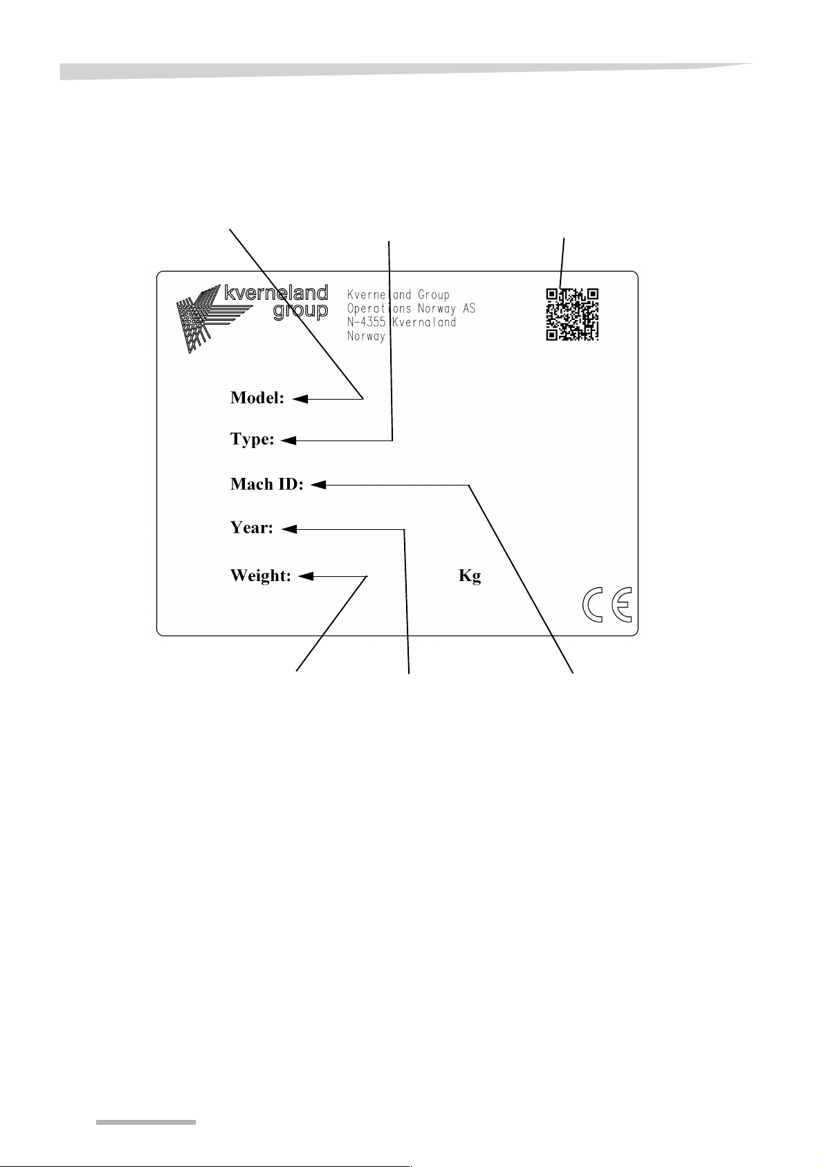
Model
Type
Body distance
Headstock
Plow ID
Production year
Weight (kg/lbs)
QR head
/lbs
bl
Information plate
The information plate is attached to the setting beam. When ordering
spare parts or consulting services, please state the full model code
and plow ID, to avoid any mistakes or misunderstandings.
20
Optional equipment
Skimmer
Trash board
This chapter provides an overview of optional equipment for the ES/
LS plow. Restrictions apply. Contact your Kverneland dealer for more
information.
Recommended for effective down-plowing of grass and stubble. Two
types of skimmer are available: the standard skimmer and the maize
skimmer. Both can be fitted with either a long share (for more effective
down-plowing of plant remains) or short share (for working more deep-
ly with the skimmer).
Available with skimmer extensions.
Particularly useful when large quantities of plant waste (manure,
straw, etc.) are present. Using a trash board gives more free space be-
tween the bodies, compared to using a skimmer.
Optional equipmen t
Disc coulter
Share knife
Disc coulters are available in sizes of 45 and 50 cm (18 and 20 inches)
in diameter, plain or cut-away for positive contact with soil to aid rota-
tion. They are fitted to single arms and are easily adjusted to suit all
conditions.
An alternative to disc coulters, when a reduction in weight may be nec-
essary or when blockage from trash or stones is likely to occur. It can
only be used on plows with fitted reversible points.
21
Optional equipment
Landside knife
Eco-plowshare
Can be used together with all types of share. An alternative to the disc
coulter, when the weight needs to be reduced or when there is a
strong likelihood of a lot of waste or stones. Ideal for combining with
skims and suitable for all types of share.
A share which reaches 10 cm (4 inches) deeper than the plow’s nor-
mal share and loosens the plowed soil. Does not need to be fitted to
all bodies. Also an alternative for up to 10 cm (4 inches) shallower
plowing.
Plowshare with
reversible point
Share with flush fit point
An effective cutting system for plowing hard and abrasive soil and in
generally difficult conditions.
For plowing in sticky soil. The point is attached using a single bolt and
can therefore be replaced easily.
22
Share with Quick-Fit
point
Share with Knock-on
point®
Optional equipment
Reduces the down time in replacing the points. Can be fitted to all plow
bodies. Very good ground penetration.
Reduces the down time in replacing the points. Can be fitted to all plow
bodies. Very good ground penetration.
Furrow splitter
Mouldboard extension
Developed for fitting to any part of the mouldboard and cutting through
hard soil, making it easier for subsequent operations. The splitter is at-
tached by a bolt in an existing hole in the mouldboard.
Mouldboard extensions can be fitted for better packing of the heaps in
firm soil and uphill
23
Optional equipment
Furrow opener
Used on the rear body to increase the width of the base of the furrow,
to accommodate tractors with wider tires.
Wear plate
Depth wheel
Can be fitted to landsides to reduce wear to the landsides. Fitted to the
landsides’ rear end as a replaceable high-wear part.
Using a depth wheel on all plows is strongly recommended. A wide
range of depth wheels are available for the plow.
Depth wheel made from steel or rubber
A sturdy depth wheel made from rubber or steel. Depth wheels are
available in two widths and diameters. The wheel’s function can be
purely mechanical or it can be equipped with different damping sys-
tems. Available as frame-mounted and rear-mounted variants.
24
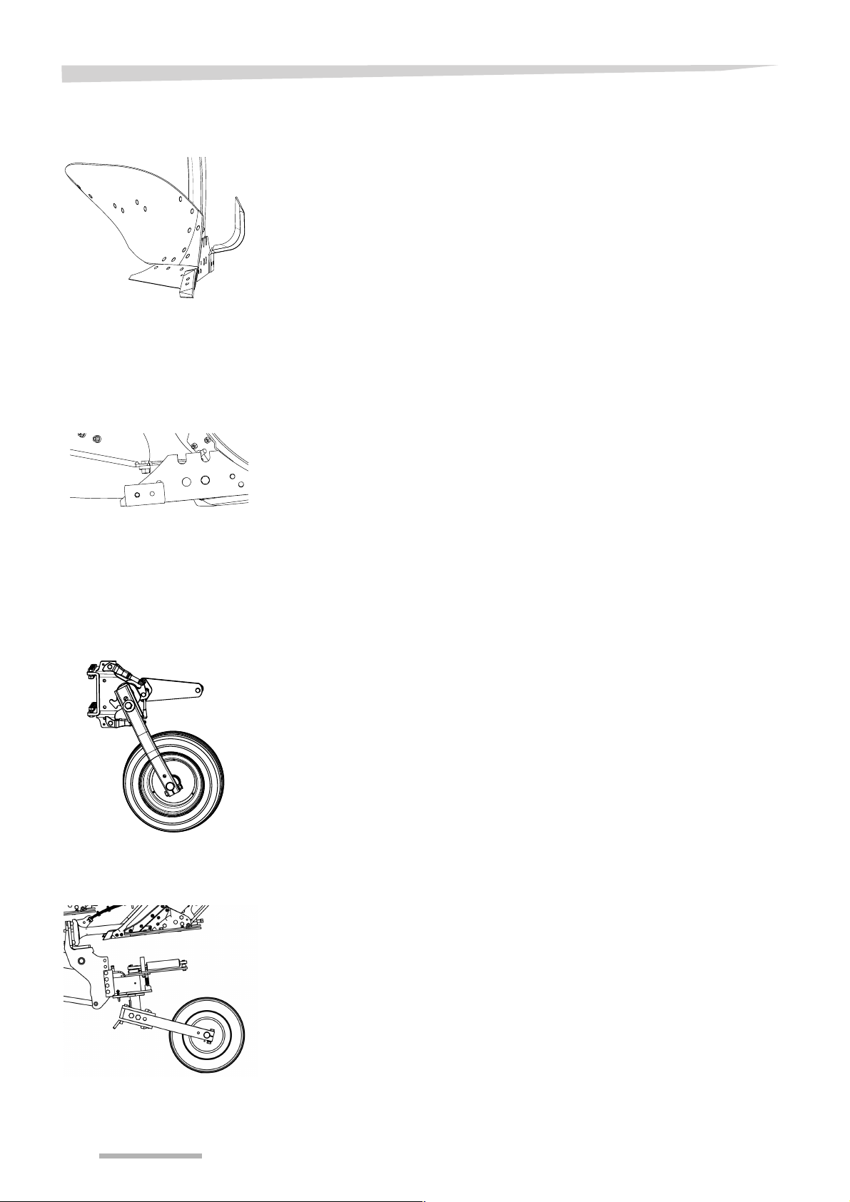
Depth/transport wheel
A sturdy rubber wheel which can be used as a depth wheel during
plowing. Can be converted into a transport wheel for road use in a few
simple steps. Available as frame-mounted and rear-mounted variants.
Rear-mounted is the simplest and commonest use (see photo). The
frame-mounted variant is used to get closer to edges (hedges, fences,
etc.) towards the end of plowing.
Optional equipment
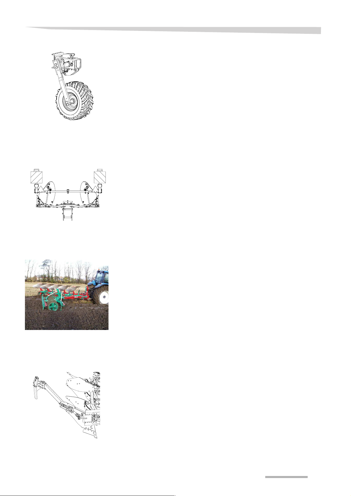
Hydraulic depth/transport wheel
A depth/transport wheel, allowing the plow depth to be set hydraulical-
ly during plowing. This cylinder function can also be used at the end
of each furrow for a more even plowing on long plows.
Lighting for transport
Packomat
Attachable/detachable lighting is available for road transport, in com-
pliance with local regulations. Several configurations are available for
the different markets. Available for transport both in plowing setting
and semi-rotated setting.
Kverneland Packomat is a soil packer which is integrated into the plow
and which ensures optimum combination of both. Kverneland’s inte-
grated soil packer harrows and packs the soil once it is in an easily
workable state, and in some cases (lightweight soil) saves all harrow-
ing, and in all cases some harrowing.
Can be supplied with a single roller or double roller section.
Soil packer arm
Available for use with the soil packer. A hydraulic cylinder releases the
soil packer on the headland.
25

Optional equipment
Hydraulic Auto-Reset
As an alternative to the leaf spring design, a hydraulic release, com-
prising a single-acting cylinder, is available [ES].
Leaf springs are replaced by a hydraulic cylinder which is connected
to an accumulator, the pressure of which can be regulated to obtain an
appropriate release force for different soil conditions.
26

Preparation for use
110–160 cm
(43-63 inches)
0–10 cm (0-4 inches) wider than the rear
This chapter details how to prepare the plow and tractor before putting
the plow into operation.
Tractor
Hydraulic connections
Hydraulic functions Single-acting Double-acting
Turnover 1
Hydraulic furrow width [+] 1
Hydraulic first furrow width [+] 1
Hydraulic depth wheel [+] 1
Hydraulic release system [+] 1
The following table shows the tractor’s required connections.
We recommend the tractor's hydraulic output flow is 25-35 l/min.
(6.6- 9.2 gpm)
Preparation for use
Depth control
Plow size Depth control of the plow
2–3 furrows |----------------------------------X------------|
4–6 furrows |----------------------X------------------------|
Track
We recommend setting the tractor’s depth control as shown in the following table. The soil and field conditions determine the precise set-
tings.
Initial settings
Tractive-power-regulated depth control
Position control<------------> Drag control
•
To use the plow, the tractor’s internal rear track (the distance be-
tween the internal edges of the rear wheels) must be 110–160 cm
(43-63 inches).
•
The internal front track (between the front wheels) must be 0 to 10
cm (0-4 inches) wider.
•
The rotating mechanism can be mounted in two ways on the plow,
depending on the distance between the rear wheels.
27

Preparation for use
T
IP
Be mindful when ordering the plow so that the slide can be fitted cor-
rectly.
Tire pressure
Front weights
Lower links
Remove paint
To prevent uneven furrows, the air pressure must be the same in both
the tractor’s rear wheels.
> Fit sufficient weights at the front to ensure safe driving.
> Adjust both the lower links to an equal height. This ensures equal
levelling of the plow in both directions.
> Remove paint from all surfaces which are in contact with the
ground. Use a scraper and paint remover.
28

Connecting
Large
plows
Small
plows
Safety
This chapter explains how to connect the plow to the tractor.
\
WARNING
Increased risk of injury when coupling
There is an increased risk of injury when the plow is coupled to the
tractor. Therefore:
•
Shut off the engine, set the parking brake, remove the ignition
key.
•
Secure the tractor to prevent it from rolling.
•
Do not stand between the tractor and plow when coupling
•
Lift and lower the plow slowly
An unsecured tractor can create hazardous conditions.
If this requirement is ignored, the consequence may be
damage to the machine and the potential for life-threatening
injuries.
Connecting
Coupling
Check the length of the hose
Check that the hose between the plow and the tractor is slack enough.
If the hoses are trapped or stretched, they can become damaged or
get torn off.
To couple the plow to the tractor
> Connect the lower link arms on the tractor to the cross shaft on the
plow
> Connect the top link on the tractor to the plow’s headstock/tower
> Relieve all hydraulic pressure from the tractor and the implement.
> Connect the hydraulic hoses to the tractor.
> Raise the plow carefully
> Stow the parking stand
> Check the connection geometry (see below)
> Reverse the plow to check the clearance with the ground and with
the tractor (see below)
TIPTop link connection
•
Use the slotted holes with 4-furrow plows and larger. Then the plow
can follow the contours of the field.
•
Use the fixed holes on 2- and 3-furrow plows. This prevents the
plow from tipping up in heavy or stony soil.
•
Make sure that the top link slopes slightly towards the tractor from
the plow.
29

Connecting
wrong
right
Connection geometry
To obtain a stable first furrow width, the intended pulling point between
the lower link arms must be 1/3 of the axle distance behind the front
axle. If this is not the case, use a cross shaft with a different length.
→ »Cross shaft« page 16.
Clearance
between the depth
wheel/plow and
the ground
Clearance
between the
tractor and plow
Reversing with the bodies above the frame
Once the plow is connected to the tractor, first make sure that the
depth wheel has sufficient clearance from the ground during revers-
ing. If there is not sufficient clearance, do one of the following:
•
Connect the top link to a higher hole on the plow
•
Connect the top link to a lower hole on the tractor
•
Position the cross shaft in a lower hole
→ »The position of the cross shaft«, page 74
If there is not sufficient clearance between the tractor and plow, rotate
the cross shaft’s attachment plates to the headstock
→ »The position of the cross shaft«, page 74
30

Transport
Safety
This chapter explains how to drive safely on the road.
When you use a Kverneland Packomat together with the plow, other
instructions apply. Read the operator‘s manual for Kverneland Packo-
mat.
\
WARNING
Stabilize the lower links
During transport, stabilize the tractor's lower links. This will pre-
vent the plow from accidentally moving sideways.
Use the transport wheel
If the plow is equipped with a depth/transport wheel, use it when driv-
ing on the road. If you do not use the depth/transport wheel, this can
result in an extreme load on both the tractor and the plow and they
may be damaged.
Disconnect the top link
When you use a depth/transport wheel, the top link should be discon-
nected. Otherwise, the contours of the road could result in extreme
forces on the plow and it could be damaged.
Transport
Adjust speed: max. 25 km/h (15 mph)
Always adjust the driving speed according to the road or field condi-
tions, but never drive faster than 25 km/h (15 mph). Driving at too high
speed leads to extreme loads on both the tractor and the plow and
they may be severely damaged.
Be aware of the plow’s length
The plow is very long and swings out when turning. Avoid allowing the
rear of the plow to hit obstacles during sharp swings.
31

Transport
Close valve
Bolt
Forward
Parking place
for bolts dur-
ing plowing
Before transport
Before transport
> Remove dirt and soil from the plow
> Raise the plow carefully
> Stabilize the lower links
> Adjust the plow to the narrowest working width
> Close the valve on the working-width cylinder [+]
> Put the plow into the transport position (see below)
> Stabilize a rotating cross shaft [+] (see below)
> Fit lights [+]
→ Assembly instructions for lightweight equipment
Stabilize rotating
cross shaft [+]
To stabilize the rotating cross shaft
> Lift the plow. This makes the plow slide forward.
> Locate the bolts in the holes on both sides of the headstock.
32

Put into transport
Transport position
Lift up
Rotate
Hole Y
Hole Z
Turn the wheel
position
Transport
Without transport wheel
Transport wheel for
butterfly position
If the plow is not equipped with a transport wheel, it should be trans-
ported as shown.
> Lift the plow 10 cm (4 inches) above the ground
> Lift up the upper depth stop
> Rotate the locking pin in order to lock the depth stop’s position. The
wheel will then be able to rotate freely
> Repeat the process for the lower depth stop.
> Remove the bolt from hole Y
> Turn the depth/transport wheel to the transport position
> Insert the bolt into hole Z
33

Transport
Turn the spring-
loaded stop
Handle
Unlock
Transport position
> Turn the spring-loaded stop. The wheel will then be able to rotate
freely through 360°.
\
WARNING
> Activate the transport lock on the headstock so that the locking
pin (spring-loaded) pops out.
> Turn the plow carefully into butterfly position. Ensure that the trans-
port lock locks.
> Lower the plow until it rests on the transport wheel.
> Disconnect the top link from the headstock.
34

Transport wheel for
2
1
Transport position
transport in plowing position
Transport
> Put the plow onto the ground (right body)
> Remove the locking piece and turn it through 180º
> Fasten it in the same place, it having been rotated through 180º
> Lift the plow.
> Remove the bolt from position 2
> Put the bolt into the hole to fasten the wheel arm (position 1)
> Lower the plow until it rests on the transport wheel
> Disconnect the top link from the tower
35

Transport
Bolt and ring pin
Lift slightly
Hole A
Hole B
Release plate
X
Y
Hole Z
Bolt
Hole Y
Handle
Unlock
Transport position
Hydraulic depth wheel
To change to transport position
> Lift the plow slightly
> Stabilize the lower links
> Adjust the plow to it's narrowest working width
> Lift the wheel slightly. This eases removing of the bolt.
> Remove bolt from hole B. This enables free rotation of the wheel.
> Move the release plate into position X.
> Insert bolt in hole A.
> Remove the bolt from hole Y
> Turn the wheel arm to the transport position
> Insert the bolt into hole Z
\
WARNING
> Activate the transport lock on the headstock so that the locking
pin (spring-loaded) pops out.
36
> Turn the plow carefully into butterfly position. Ensure that the trans-
port lock locks.
> Lower the plow until it rests on the transport wheel
> Disconnect the top link from the tower

Transport
Transport position
Lock
Unlock
Handle
Hole Y
Hole Z
Turn the wheel
Turn the spring-
loaded stop
Set into the plowing position
Transport wheel for
butterfly position
After transport, set the plow back to the working position.
> Connect the top link to the tower
> Lift the plow right up.
> Deactivate the transport lock on the headstock, i.e. press in the
locking pin
> Carefully turn the plow to the plowing position.
> Remove the bolt from hole Z
> Turn the depth/transport wheel to the working position
> Insert the bolt into hole Y
> Turn the spring-loaded stop at the same time as slightly lifting the
wheel arm so that the wheel points backwards
37

Transport
Rotate
> Release the locking hooks for the upper and lower depth stops so
that these can move freely.
38

Set into the plow-
2
1
ing position
Transport wheel for
plowing position
Transport
> Connect the top link
> Lift the plow
> Remove the bolt from position 1
> Put the bolt into the hole to fasten the wheel arm (position 2)
> Lower the plow to the ground
> Remove the locking pin and turn the stop plate through 180º
> Fasten it in the same place in the rotated position
39

Transport
Transport position
Handle
Unlock
Lock
Hole Z
Bolt
Hole Y
Bolt and ring pin
Lift slightly
Hole A
Hole B
Release plate
X
Y
Hydraulic depth wheel
To change to plowing position
> Connect the top link to the tower
> Lift the plow right up.
> Deactivate the transport lock on the headstock(pull the locking pin
back)
> Turn the plow into plowing position
> Remove the bolt from hole Z
> Turn the wheel arm to the plowing position
> Insert the bolt into hole Y
> Remove the bolt from hole A
> Move the release plate to position Y.
> Lift the wheel into working position
> Insert bolt in hole B
40

Adjust the plow
Safety
This chapter explains how to adjust the plow in order to achieve the
desired plowing result.
The adjustments can be made either before or during plowing.
Recommended procedure
We recommend that you use the following procedure, in this order,
when adjusting the plow in the field
> Working width
> First furrow width
> Working depth with depth wheel, depth control and top link
> Sideways levelling
> Disc coulter, skims and leaf spring
If one function is adjusted, this will affect the others. Therefore, these
adjustments must be made repeatedly.
Instructions for adjusting Packomat can be found in the Packomat op-
erator‘s manual.
Adjust the plow
Working width
\
WARNING
Use protective clothing
Use protective clothing, e.g. gloves, when working with sharp
parts of the plow. Parts that come into contact with the soil can be
very sharp. Failure to handle these carefully may lead to injury.
Do not wear loose fitting or other inappropriate clothing. Loose
fitting items of clothing may become caught in parts of the plow.
Wear the proper protective clothing. Different environments may
require special clothing to preform the operation and maintenance
of the plow. Serious or fatal injury may be caused if these guidelines
are not followed.
Adjusting the working with takes two steps
> Adjust the frame angle as described below
> Adjust the first furrow width (see next page)
T
IP
The scale indicates the working width for each body, in inches and
centimetres
41

Adjust the plow
This diagram shows hydraulic working-width
adjustment
Working width
Stop nut
Working width
Mechanically
> Adjust the working width on the turnbuckle. Use the spanner which
is supplied.
Hydraulically [plows without alignment cylinder]
> Adjust the working-width cylinder using the tractor’s hydraulic out-
let
Hydraulically [plows with sequence valve]
> Swing the plow slightly inwards by starting the rotating sequence
with the tractor’s spool valve
> Adjust the stop nut on the alignment cylinder
> Swing the plow out by activating the tractor’s spool valve in the op-
posite direction.
If working with a very narrow working width, you can use spacers on
the cylinder.
Hydraulically [plows with memory valve (sequence)]
> Adjust the memory cylinder with the tractor’s spool valve control.
The cylinder can be connected to a separate outlet on the tractor, or
together with the headstock hydraulic cylinder, as a sequence or
memory sequence.
42

First furrow width
Wrong adjustment
Right adjustment
This diagram shows how to adjust the first fur-
row hydraulically
First furrow cylinder
Adjust the plow
\
WARNING
Do not adjust when lifted
Do not adjust the first furrow width when the plow is lifted from the
ground. This may lead to damage or injury.
In general, the first furrow must agree with the width of the others.
Pay careful attention to the following:
•
If the tractor is fitted with wide tires, the first furrow width should be
reduced to maintain a good connection with the preceding furrows.
•
When working on an incline, the plow’s drifting downhill should be
compensated for.
•
When using a furrow opener on the last body, the first furrow width
should be 13 cm (5 inches) narrower than the width of the other fur-
rows.
Mechanically
> Adjust the first furrow width using the adjustable bolt. Use the
spanner which is supplied.
Hydraulically
> Adjust the first furrow width cylinder using the tractor’s solenoid-
valve control.
43

Adjust the plow
Wrong adjustment
Right adjustment
Depth stop
Counter nut
Both stops the same length
L
Working depth
•
The plow frame should always remain parallel to the ground.
•
The top link should be in the centre of the tractor.
•
After changing the working depth, the sideways levelling should be
checked (see next section)
Depth wheel
Changing the plowing depth
> Raise the plow carefully
> Adjust the depth wheel (see below)
> Adjust the lower link arms with the tractor’s three-point control
> Adjust the length of the top link
> Level the plow sideways
→ »Levelling«
To adjust the depth wheel, do the following with both depth stops
> Adjust the counter nut
> Adjust the depth stop
> Tighten the counter nut again
TIPA useful way to measure the working depth, both on the left and the
right
44
> Measure the depth of the last furrow
> Measure the length of both stops. Ensure that both stops are of the
same length.

Adjust the plow
Scale
Spacer cap
Bolts
Hydraulic depth wheel
[+]
Adjust the working depth more shallow than adjusted with mechanical
stops by activating the single-acting cylinder
> Activate the tractor’s spool valve.
•
Pull the cylinder back towards the stop in order to plow deeper.
•
Lengthen the cylinder in order to plow shallow
T
IP
The scale indicates the plowing depth.
Adjusting the normal plowing depth (maximum plowing depth)
To adjust the maximum plowing depth
> Pull out the cylinder in order to provide sufficient space to turn the
spacer
> Turn the spacer, by hand or with a screwdriver
Adjusting the arm length
To adjust the wheel to suit the plow and plowing depth, you can adjust
the wheel arm in 55-mm (2 inches) steps.
> Untighten the bolts
> Place the wheel arm in the desired position
> Insert the bolts and tighten them
B
TIPFor all wheels:
Adjust the arm as long as possible in order to ensure a good distance
between the stop and the axle. This ensures that the wheel will work
properly.
45

Adjust the plow
Wrong adjustment
Right adjustment
Adjustment bolts
Levelling
Seen from behind, the plow beams should be at right angles to the
ground.
Headstock 200
Levelling the plow
> Turn the plow slightly
> Turn the adjustment bolts on the headstock. Adjust both sides the
same to begin with.
> You can adjust the left and right sides unevenly.
46

Normal position
Level adjusting
stop arm
(Cross-section of
the levelling adjust-
ing bolt)
Risk of col-
lision
Frame
Adj. bolt
Level adjusting
stop arm
(Cross-section of the
levelling adjusting
bolt)
Risk of col-
lision
Frame
Adj. bolt
Adjust the plow
\
CAUTION
Extremely deep or shallow plowing
The rotating system on headstock 200 must never be in contact
with the frame of the headstock. This can occur when
•
You are plowing shallow and the bodies rotate over the frame
•
You are plowing deeply and the bodies rotate under the frame
The load should always be under pressure from the rotating system;
under no circumstances may the rotating system rest on the frame.
Alternative position
47

Adjust the plow
1/3 D
D
> 5 cm
(>2 inches)
1-4 cm
(0.4-1.6 in.)
Turning stop
Bolt T
Eccentric
Bolt U
Bolt U
Disc coulter [+]
The disc coulter is correctly adjusted
•
When the disc coulter cuts to about half the working depth in the
soil.
•
When the distance between the disc coulter and the body is at least
5 cm (2 inches). This distance is to be increased on stony ground.
•
When the rear disc coulter does not collide with the depth wheel.
•
When all the disc coulters are adjusted the same
•
When the distance between the disc coulter and the landside is be-
tween 1 and 4 cm (0.4-1.6 inches).
ES without parallel side
adjustment
Adjusting the depth
> Support the disc coulter to prevent it falling down
> Loosen the bolt (T)
> Adjust the depth
> Tighten the bolt again (T)
Adjusting the side position
> Loosen the bolts (U)
> Release the eccentric
> Tighten the bolts again (U)
Adjusting the amount of swing
> Support the disc coulter and hold it in place
> Loosen the bolt (T)
> Release the turn stop to the desired position
> Tighten the bolt again (T)
48

ES with parallel side
Arm
Bolt R
Stem
Bolt S
B
A
Bolt C
Eccentric
adjustment
Adjust the plow
Adjusting the depth
> Support the disc coulter to prevent it falling down
> Loosen the bolt (R)
> Turn the arm
> Tighten the bolt again (R)
Adjusting the side position
> Loosen the bolt (S)
> Turn the stem
> Tighten the bolt again (S)
LS
Adjusting the depth
> Support the disc coulter to prevent it falling down
> Loosen the bolt (B)
> Turn the arm
> Tighten the bolt again (B)
Adjusting the depth further, for very shallow or very deep plow-
ing
> Support the disc coulter to prevent it falling down
> Loosen the bolt (C)
> Adjust the axle position
> Tighten the bolt again (C)
Adjusting the side position
> Loosen the bolts (A)
> Release the eccentric
> Tighten the bolts again (A)
49

Adjust the plow
B
C
B
C
A
A
C
C
Y
X
Skimmer [+]
ES
The skims are correctly adjusted when
•
The skims have a working depth of approx. 3–5 cm (1.2-2 inches).
•
All the skims have been adjusted the same.
Adjusting the depth
> Support the skims to prevent them falling down
> Loosen the nut on bolt C
> Loosen bolt C, one side at a time
> Adjust the skims to the desired position, and count the markings
> Tighten the bolt again (C)
> Tighten the nut again (C)
Adjusting the forward position
> Loosen the nuts (A) at the same time
> Loosen the nuts (B) at the same time
> Adjust the skims to the desired position
> Tighten the nuts again (B)
> Tighten the nuts again (A)
LS
Adjusting the depth
> Support the skims to prevent them falling down
> Loosen the nut on bolt C
> Loosen bolt C, one side at a time
> Adjust the skims to the desired position, and count the markings
> Tighten the bolt again (C)
> Tighten the nut again (C)
Changing the forward position
> Support the skims
> Loosen and remove the nuts and conical pieces (X)
> Lift the entire skim assembly to the second position (Y)
> Fit the nuts and conical pieces and tighten
N
OTE
Be aware when mounting the skimmer of the first body on shearbolt plow. There
is a risk that the share of the skimmer can collide with the turnover
cylinder, during turning the plow, when moving the skimmer forward from
the standard position shown in the figure.
50

Adjust the plow
B
A
A
B
B
Trash board [+]
The trash board should be positioned with its front edge tight up to the
mouldboard; its back edge should be adjusted in accordance with the
plowing depth.
The bracket for the trash board has two adjustment holes, one for
deep plowing and one for more shallow plowing (A). There are also
two slots in the trash board to allow for additional adjustment (B).
TIP!
When commissioning the new plow, it is a good idea to adjust the trash
board in the upper position to strip the paint from the plow bodies when
plowing.
TIP!
It may be a good idea to adjust the height of the trash board when
changing the working width.
Soil packer arm [+]
Position of the packer
•
Place the conventional packer so that it allows at least two furrows
to remain unpacked. This allows you to check the connection be-
tween following rounds.
•
The length of the arms (B) must be adjusted so that the tractor
wheel runs clear when you are returning.
> Adjust the stay tightener (A)
51

Adjust the plow
direction of drive
15°
Protection plate
Direction of the packer
arm
•
The packer arm should always be fitted at an angle of 15° to the
direction of drive.
•
There are three possible settings. When using setting 1, a pusher
is fitted to protect the hydraulic hose.
Setting 1 Setting 2 Setting 3
52

Plowing
Plowing
Safety
Before plowing
Be careful when you reverse when driving backwards (when
turning with bodies under)
Be careful when reversing the plow while driving backwards. There is
a risk of mouldboards or the depth wheel hitting the ground. This may
result in damage.
Release the stabilizer bars
Destabilize the tractor’s stabilizer bars before plowing. If plowing is
done when the lifting bars are still stabilized, this can result in damage
to the tractor or the plow.
Plowing on a slope
Do not reverse the plow when the tractor is standing sideways on a
slope. If the plow is reversed, this can result in the tractor becoming
unstable.
Before you begin to plow
> Remove all oil and grease from parts which are in contact with the
ground.
> Release the lower link arms
> Turn the depth/transport wheel to the plowing position
→ »Set into the plowing position«Maintenance intervals, page 37
Check during
plowing
Regularly check the following during plowing.
Penetration into the ground
When plowing hard or dry ground, it is possible that the plow will not
force down well. To achieve better penetration
> Replace worn-out parts. Worn tips do not penetrate into the
ground.
> Connect the top link the fixed hole position on the headstock.. This
transfers the weight from the tractor to the plow.
> Connect the top link to the tractor and the plow as flat as possible.
Tractor wheels sliding (on two-wheel-drive tractors)
To reduce the sliding of tractor wheels
> Connect the top link to a fixed hole on the headstock and make the
top link shorter. This prevents the back end of the plow from tipping
up.
> Adjust the tractor’s depth control more in the direction of the rheo-
static regulator, or do not plow so deep.
»Checklist« page 77
53

Plowing
Reversing the
plow
Different change-over
valve systems
\
CAUTION
Complete the turning sequence
Always complete the entire turning sequence. Only then the turn-
over cylinder will be locked, and will not rotate during plowing.
The plow reverses when you apply pressure to the P side of the turn-
over valve. The turning sequence is dependent on the type of turnover
valve.
> Activate the tractor’s spool valve until the turning sequence has
been completed.
Turnover valve – only for turning the plow
•
The plow reverses completely from one side to the other side
Turnover sequence valve
•
The plow should first be set to the narrowest working width
•
The plow reverses completely from one side to the other side
•
The plow goes back to the working width which is set with the me-
chanical stop.
Soil packer arm [+]
Turnover (sequence) memory valve
•
The plow should be set to the narrowest working width
•
The plow reverses completely from one side to the other side
•
The plow goes back to the working width which is set with a sepa-
rate outlet on the tractor
When you use a packer arm for a conventional packer, you must re-
lease the soil packer just before you get to the marking furrow
> Activate the tractor’s spool valve for a short while in the opposite
direction of reversing.
54

Care and maintenance
Safety
This chapter explains necessary maintenance and care of the plow.
\
CAUTION
Use original spare parts
Only use original Kverneland spare parts. Using other products
may lead to malfunction of the machine or a reduced safety. War-
ranty is not valid if parts not produced by Kverneland are used.
\
WARNING
Wear protective clothing
Wear protective clothing, e.g. gloves, when working with sharp
parts of the plow. In particular, parts which come into contact with
the soil can be very sharp. Careless handling can result in injury.
Avoid skin contact with oil and lubricants
When handling oil or lubricants, avoid contact with the skin by using
oil-resistant gloves. Oil and lubricants can damage the skin.
Care and maintenan ce
Before
maintenance
\
WARNING
Before maintenance is carried out on the plow
> Ensure that the plow is correctly secured to prevent overturn-
ing. Use additional safety devices when required
> Depressurize the hydraulic system
> Whenever possible, uncouple the tractor
> Place all controls in neutral or park
> Set tractor parking brake
> Switch off the tractor and remove the ignition key
> Ensure the machine is standing on firm, secure and level
ground, and provide additional support, if necessary
> Secure the machine against rolling away (use wheel chocks)
> Clean the plow around the area requiring maintenance
55

Care and maintenance
Maintenance table
Check condition of the plow X X
Lubrication X X X X
Replace the hydraulic hoses X X
This maintenance table shows the maintenance interval for the vari-
ous maintenance procedures.
after the first few hours in use
daily
before the plowing season
after the plowing season
after high-pressure cleaning
annually, or after every 200 ha (500 acre)
in the event of wear or damage
After 1000 km (621miles) of transport
every 6 years
Replace worn parts X
Retighten bolts and nuts X X
Check the release-system springs X
Check the tire pressure X X
Protect parts which are in direct contact with the
ground against corrosion
Align the bodies X
Replace cross shaft X
Check the preload pressure of the hydraulic release
system
Cleaning
Thorough cleaning will help the plow to last longer.
•
The plow can be cleaned with a high-pressure cleaner, but never
aim directly at the bearings
•
Grease all grease fittings after high-pressure cleaning.
X
X X
56

Care and maintenance
Lubrication
Use appropriate grease
Only use EP (Extreme Pressure) grease. The use of inappropriate
grease will reduce the lifetime of the bearings.
Lubricate the plow
•
Daily during plowing. This prevents water and dirt from penetrating
into the bearings and moving parts.
•
After high-pressure cleaning
•
Before and after the plowing season.
> Lubricate all lubrication points until lubricant comes out of the bear-
ing.
> Remove any excess lubricant. Dust and soil will stick to excess lu-
bricant.
57

Care and maintenance
S
S
S
S
S
S
S
S
S
S
S
S
S
The diagrams below show the lubrication points (S)
Lubrication points (S)
Headstock 2000 Disc coulter
Automatic beam
In front [ES] In front [LS]
58

Care and maintenance
S
S
S
S
S
S
S
S
S
S
Lubrication points (S)
Depth/transport wheel for plowing position Depth/transport wheel for butterfly position
Depth wheel Hydraulic depth wheel [+]
Hydraulic depth wheel [+]
59

Care and maintenance
Replace hoses
\
Check the length of the hose
Check the length of the hose on the plow for sufficient slack.
Overly taut or stretched hoses can become damaged or broken.
\
Replace the hydraulic hoses
•
Immediately when they have become worn or defective.
•
Every 6 years
> Release the pressure in the hydraulic system
> Connect the hoses from the tractor
> Remove the old hose.
> Fit the new hose
> Carefully tighten all connections
WARNING
WARNING
Replace worn
parts
•
Replace all parts which go down into the ground and other parts
when they are worn out or damaged.
•
Use original Kverneland parts only.
> Remove the old part.
> Fit the new part
> Remove paint from all surfaces which are in contact with the
ground.
TIPLandsides
When rotating landsides are worn down to approx. 5 mm (0.2 inches)
at the end, they can be rotated from the bodies on the right-hand side
to the left-hand side.
TIPReversible point
When reversible points are worn out on the outermost edge, they can
be reversed.
60

Replace Quick-fit
Care and maintenance
points
\
WARNING
Wear eye protection
•
Wear eye protection when replacing Quick-fit points. Other-
wise, there is a risk that splinters from the Quick-Fit points can
cause eye damage.
Removing a worn point
> Place the gore tool
> Knock the point out with an appropriate hammer.
Fitting a new point
> Place the point in front of the share an move it backwards
> Use the gore tool as a buffer between the point and the hammer
> Knock the point into place
Replace Knockon® points
TIP!
There must be no paint on the angled surfaces
TIP!
Rotating the Quick-fit points.
When the Quick-fit points are approximately 50% worn, they can be
moved from the body on the right-hand side to the left. This gives bet-
ter penetration.
\
WARNING
Wear eye protection
•
Wear eye protection when replacing
wise, there is a risk that splinters from the
can cause eye damage.
Removing a worn point
> Place the gore tool
> Knock the point out with an appropriate hammer.
Knock-on®
Knock-on®
points. Other-
points
61

Care and maintenance
Fitting a new point
> Place the new point in front of the share and move it backwards
> Use the gore tool as a buffer between the point and the hammer
> Knock the point into place
TIP!
There must be no paint on the angled surfaces
Tighten bolts and
nuts
General
Bolt
diam.
10.9 Bolts 12.9 Bolts
kpm (ft lbs) Nm kpm (ft lbs) Nm
M12 11.5-12.5 (83-90) 113 - 122.5 14-15 (101-108) 137 - 147
M14 18.5-20 (134-145) 181.5 - 196 22-24 (159-174) 216 - 235.5
M16 28.5-31 (206-224) 279.5 - 304 34-37.5 (246-271) 333.5 - 368
M20 55.5-61 (401-441) 544.5 - 598.5 65.5-73 (474-528) 652 - 716
M24 95-105 (658-759) 932 - 1030 115.5-127 (835-919) 1133 - 1246
Tighten all bolts and nuts on the plow again.
•
After the first few hours in use
•
Whenever necessary
•
Annually, or after every 200 ha (500 acre)
The table below applies for most bolts and nuts.
Tightening torque
62

Specific tightening
M30 left-hand
side
588 Nm
60 kpm
M30 right-hand
side
588 Nm
60 kpm
shear bolt M20
545–600
Nm
55–61 kpm
M30
1500 Nm
160 kpm
M16
412 Nm
42 kpm
torque
Beam with shear bolt [LS] Headstock 200
Care and maintenance
Replace shear bolt
[LS]
Check springs for
correct length
Fit only original shear bolts
Fit only original shear bolts. Use of unoriginal shear bolts can lead to
damage of the plow.
LS is equipped with shear bolts for protection against solid objects in
the ground.
When a shear bolt shears:
> Replace it with an original shear bolt
> Retighten all bolts (see diagram)
The length of the springs from locking bolt to locking bolt must be 70
cm (28 inches). This results in maximum spring tension. Over time, the
spring adjustment can gradually be changed, and so therefore this
must be corrected.
> Check the length of the springs every year.
> Adjust the length if they are shorter or longer than 70 cm (28 inch-
es).
→ page 69
63

Care and maintenance
70 cm
(28 inches)
F
F
TIPUse the long spanner to measure the spring length. The notches on
the spanner indicate 70 cm (28 inches).
TIPCheck the spring bolts (F) for wear. Replace them if necessary.
Tire pressure
Set the bodies
Ensure that the tires are inflated to the necessary pressure.
→ »Tire pressure«Maintenance intervals, page 19
New plows are delivered with adjusted bodies. Use of the plow can
gradually change the settings. Therefore, check the setting of the bod-
ies after each plowing season
The bodies are correctly set when
•
A2 = A1
•
B2 = B1
•
A2 = B2
The maximum permitted discrepancy between A1 and A2 is 5 mm (0.2
inches). If there is a greater discrepancy, the bodies are to be adjusted
with the nuts on the braces.
> Start with the middle body.
> Loosen the counter nut
> Adjust the nut until the body is in the desired position
> Tighten all the nuts, including counter nuts
> Continue with the other bodies.
64
Also check that the bodies on the left-hand and right-hand sides are
parallel.
> Inspect the left-hand and right-hand braces above to confirm that
they are parallel
> Adjust if necessary.

Check the preload
Quick connection
slowly
suddenly
preload pressure
Care and maintenance
pressure of the
hydraulic release
system [+]
\
WARNING
Couple to the tractor and support the beams
When checking, couple the plow to the tractor and place the plow
on firm and level floor. Support the beams with a wedge under the
landsides. Releasing of the pressure may otherwise cause the
beams or the plow to drop down.
Connect/disconnect the filling hose
Due to the pressure in the hydraulic system, the filling hose cannot be
connected/disconnected directly to/from the tractor. Therefore, a special quick connection is used on the accumulator, which can be con-
nected/disconnected under pressure.
To connect the filling hose.
> first connect the hose to the tractor
> then connect the hose to the accumulator
To disconnect the filling hose.
> first disconnect the hose from the accumulator
> then disconnect the hose from the tractor
Checking the nitrogen
preload pressure
The preload pressure is nitrogen in the accumulator when the ram is
in the outermost position. The factory-set preload pressure is 90 bar
(1305.3 psi). This preload pressure may gradually fall over time.
•
Check the preload pressure before and after each plowing season.
•
Put in some nitrogen when the preload pressure falls below 80 bar
(1160.3 psi).
Before checking
> Connect the plow to the tractor
> Place the plow on a firm and level surface
> Support the beams with a wedge under all landsides.
> Remove the dust covers
> First connect the filling hose to the tractor
> Then connect the leading hose to the quick connection on the ac-
cumulator
Checking
> Observe carefully with the manometer
> Carefully open the tractor’s spool valve.The oil pressure will now
be slowly reduced
•
The pressure shown immediately before it falls suddenly is the
preload pressure
65

Care and maintenance
Hose for oil refilling to
the tractor
Quick connections
Ram
free to move
Gas valve
Do not touch
Min 100 bar (1450.4 psi)
Max 160 bar (2320.6 psi)
TIPTo check again
> Set the system under pressure to 100 bar (1450.4 psi)
> Repeat the checking procedure.
After checking
> Set the pressure of the system to 100–160 bar (1450.4- 2320.6
psi), depending on the conditions on the ground
> Disconnect the filling hose from the quick connection on the accu-
mulator
> Disconnect the filling hose from the tractor
> Refit the dust covers
Refilling
Refilling must be carried out at a special service station.
•
Refill the accumulator when the preload pressure falls below 80
bar (1160.3 psi).
•
Refill the accumulator with nitrogen to 90 bar (1305.3 psi).
66

Possible modifications
A
B
Reversing
direction
Restrictor position
This chapter explains how you can alter some of the plow’s basic con-
figurations in order to adapt it to the tractor and your requirements.
The plow can be turned with the bodies either over or under the frame.
In order to change the reversing direction, you must change
•
The hydraulics configuration
•
The (sequential) change-over valve
•
The headstock configuration
> Please contact your dealer if you want to change the reversing di-
rection
A restrictor is fitted to the turnover cylinder in order to make the reversing smoother. Always fit restrictors in accordance with the following ta-
ble.
Type of turnover Restrictor position
Headstock 200
Possible modifica tions
body over A
body under B
Packomat (integrated) B
67

Possible modifications
Pull out (A)
Pull out (F)
Insert the bolt
Press forwards
Spring release
system [ES]
Safety
This section explains how you can
•
Fit or remove an automatic beam
•
Change the automatic beams’ spring tension
•
Adjust the spring tension of automatic beams
\
WARNING
Support the beam
Support the beam firmly when disassembling it, by using appropri-
ate equipment. Dropping down of the beam may lead to damage
to the plow or personal injury.
\
WARNING
Use an even, horizontal floor
Only remove a beam when the plow is parked on a horizontal and
even floor. Otherwise, the beam could fall. This can result in dam-
age to the plow or personal injury.
Fit or remove
Fit or remove an automatic beam
•
When a beam is displaced after striking an object in the ground
•
To change the beam’s release force
•
To remove the last body to make pulling easier
•
In other unforeseen circumstances
To remove the beams
> Release the spring pressure
→ Page 70
> Pull out the spring bolt (F) if necessary
> Pull out the axle
68
To fit the beam
> Position the beam into the beam bracket
> Push the tie bar forwards
> Insert the bolt into the hole
> Apply spring pressure
→ Page 70

Possible modifications
Bolt E: Clearance to
the hole in the wall
Bolt X: Adjusting the length
of the spring
1–2 mm (0.03-0.07 inches) clearance
70 cm
(28 inches)
Spring tension
The diagram shows how the transfer mechanism for the power from
the spring is to be set
For instructions, see next page.
69

Possible modifications
Loosen
Press forwards
Loosen a little
E
X
Bolt E
Bolt J
Bolt X
Tie bar H
1–2 mm (0.03-0.07 inches) clearance
70 cm
(28 inches)
To release the spring tension
> Park the plow on a firm, level surface.
> Support the beams correctly. Place a wedge under the back side
of the landside
> Loosen bolt X
> It is only necessary to loosen bolt E if you are going to remove the
beam.
To increase spring tension
> Turn the bolt (X) halfway in
> Turn in bolt (E) until the clearance between the tie bar (H) and the
hole in the wall is 1–2 mm (0.03-0.07 inches)
> Turn in bolt (X) until the length of the spring is 70 cm (28 inches).
> Tighten the bolt (J)
70
T
IP
Use the long spanner to measure the spring length. The notches on
the spanner indicate 70 cm (28 inches).

Possible modifications
Change the release force
setting
Type of spring Release force*
Standard 7.0 (1573.7 Ibs)
Standard + 1 leaf no. 5 8.0 (1798.5 Ibs)
Standard + 2 leaves no. 5 (for HD springs) 9.0 (2023.3 Ibs)
Standard + 3 leaves no. 5 10.0 (2248.1 Ibs)
Standard + 4 leaves no. 5 (for extra HD springs) 11.0 (2472.9 Ibs)
The release setting’s release force is correct when the beams do not
become loose during plowing unless they strike an object.
You can change the release force of the automatic beam by
•
Adding or removing spring leaf no. 5
•
Using a double spring assembly
Do as follows
> Release the spring tension (see page 70)
> Change the configuration of the automatic beam’s spring.
> Reapply the spring pressure (see page 70)
kN (Ibs)
Standard + 5 leaves no. 5 12.0 (2697.7 Ibs)
Double (2 x standard) 14.0 (3147.3 Ibs)
These values apply for low beams (clearance of 70 cm (28 inches)
71

Possible modifications
Leaf F
No. 1
No. 2
No. 3
No. 4
Leaf F
No. 1
No. 2
No. 3
No. 4
No. 5
No. 4
Leaf F
No. 1
No. 2
No. 3
No. 4
No. 4
No. 5
Quick connection
Standard Heavy Duty Extra Heavy Duty
Hydraulic release
system [+]
\
CAUTION
Pressure range 100 - 160 bar (1450.4- 2320.6 psi)
Never exceed the pressure range. Exceeding the pressure range
can result in damage to the system.
Connect/disconnect filling hose
Due to the pressure in the hydraulic system, the filling hose cannot be
connected/disconnected directly to/from the tractor. Therefore, a special quick connection is used on the accumulator, which can be con-
nected/disconnected under pressure.
To connect the filling hose.
> First connect the hose to the tractor
> Then connect the hose to the accumulator
To disconnect the filling hose.
> First disconnect the hose from the accumulator
> Then disconnect the hose from the tractor
72

Possible modifications
Locking nut
Adjustment bolt
Adjust the pressure to the minimum pressure when the bodies are
maintained in the working position during normal plowing.
> Remove the dust covers
> First connect the filling hose to the tractor
> Then connect the filling hose to the quick connection on the accu-
mulator
> Adjust the pressure as desired
> Disconnect the filling hose from the quick connection on the accu-
mulator
> Reduce the oil pressure in the filling hose
> Disconnect the filling hose from the tractor
> Refit the dust covers
Transfer the pressure in the
change-over valve
Problem Possible solution Turn the adjustment bolt
The plow rotates halfway and goes back to
the original position.
The plow rotates halfway and stops Reduce the valve pressure Anticlockwise (1 whole turn = 5 bar/
Do not open the valve.
Never open the valve yourself. Opened valves are difficult to remount,
and dirt may intrude in the valve. This may lead to damage. Opening
of the valve must only be done by trained service personnel
For safe rotating of the plow, the supplied pressure must be at least
160 bar (2320.6 psi). It is recommended that the oil flow be between
25 and 35 l/min. (6.6 and 9.2 gallons/min.)
The change-over valve controls the direction of the oil flow to the turn-
over cylinder. In certain cases the switch pressure must be adjusted..
Increase the valve pressure. Clockwise (1 whole turn = 5 bar/
72.519 psi)
72.519 psi)
Adjusting the valve pressure
> Loosen the locking nut
> Turn the adjustment bolt
> Tighten the locking nut again
73

Possible modifications
Cross shaft
Bolts
Bracket
The position of the
cross shaft
Headstock 200
Quick connection (long) Quick connection (short) Fixed
The cross shaft has various possible configurations, to change
•
The clearance to the tractor
•
The clearance to the ground during rotation
•
The lifting requirement
The diagrams below show the various configurations.
To change the cross shaft’s forward position [both quick connection
and fixed cross shaft]
> Remove the cross shaft
> Unturn the bolts
> Turn the brackets over and install on the opposite side of the head-
stock
> Tighten the bolts again
> Fit the cross shaft
74

Safety
Higher position
Use the support stand
Parking and
storage
Parking and storage
Parking and stora ge
\
WARNING
Parking stand
Use the parking stand when parking the plow. If the plow is not
properly supported, it may tip over. This may damage the plow or
lead to injury.
Park on a firm, even surface
Park the plow on a firm and level surface.
Parking
> Put the plow into the higher position.
> Set the pressure of the hydraulic automatic release system [+] to
100 bar (1450.4 psi) to prevent gas leakage in the accumulator.
> Use the support stand
> Park the plow
> Disconnect the plow from the tractor
> Lubricate all parts which are in direct contact with the ground. Use
only biodegradable oil and grease.
> When storing the plow, carry out all necessary maintenance.
Plow with Ecoplowshare [+]
Storage
When the plow is equipped with an Eco-plowshare only on the last
body
> Remove the plowshare before parking
> Park in the normal manner
or
> Extend the parking stand by 10 cm (4 inches)
> Place a 10-cm (4 inches)-high block of wood under the first body
> Park the plow
When the plow is equipped with an Eco-plowshare on all bodies
> Extend the parking stand by 10 cm (4 inches)
> Park the plow
The plow is equipped with components made of plastic and rubber,
and should therefore be kept away from direct sunlight during longterm storage. This particularly concerns mouldboards on bodies and
skims, and also wheels.
75

Troubleshooting
Problem Possible cause Solution
Rotating system
Troubleshooting
The plow will not start reversing The connections to the tractor have
been installed incorrectly.
The plow will not start reversing –
the plow reacts with an abrupt start
only when the oil pressure to the
change-over valve is increased
The plow turns halfway and stops,
or goes back to the original position.
The rotation stops on the first swing
cycle with a plow with Packomat, or
when rotating the plow with the bod-
ies under the main frame
Vibration during rotation The restrictor is installed on the wrong
The valve pressure is wrong Increase the valve pressure by
The restrictor regulation is installed
on the wrong port
The valve pressure is wrong Increase or reduce the valve pres-
The transfer is taking place too early,
shortly before the dead point is
reached
port
Ensure that the quick connections
have been correctly connected
(see the colour coding on the hos-
es)
turning the change-over valve
clockwise a couple of turns (see
»Transfer the pressure in the
change-over valve« on page 73)
Change the restrictor position (see
restrictor position, page 67)
sure.See Transfer the pressure in
the change-over valve, page73
Increase the valve pressure by a
couple of turns clockwise (see
»Transfer the pressure in the
change-over valve« page 73). Ensure that the restrictor in the turno-
ver cylinder is correctly located (see
»Restrictor position«, page 67)
Change the restrictor position, see
»Restrictor position«, page 67
Rotation takes place more slowly on
heavy plows and is possibly not
completed.
The swing or in-swing cylinder
creeps during plowing or transport
Operational
The first furrow width is different
when plowing on the left-hand side
and the right-hand side
Problem with the oil flow Test to see whether different oil flow
speeds affect the rotation by adjust-
ing the engine speed or the flow
speed of the motor-operated valve;
change-over valves operate opti-
mally with 25–35 l/min (6.6-9.2
gpm). High flow speeds can return
pressure and cause weaker rotat-
ing performance
The swing phase is not completed
and the cylinder is not locked
Gasket(s) in the turnover cylinder leak Contact your dealer
Leakage in the change-over valve Contact your dealer
The cross shaft is not placed centrally
on the headstock
The tractor’s rear tires are not inflated
to the same pressure
Complete the swing phase, then
apply valve pressure (see »Revers-
ing the plow«, page 54). On plows
with a memory system, all adjust-
ments to the working width should
be made with the variable-width le-
ver, not with the rotation lever
Place the cross shaft centrally un-
der the headstock
Adjust the air pressure
76
The sideways levelling is wrong Adjust the levelling

Checklist
Checklist
Tractor
Fitting
Driving on the road
Check
•
Is the internal track (the distance between the inside of the wheels)
110–160 cm (43-63 inches)?
•
Is the pressure in the left-hand and right-hand tires the same?
•
Are both of the lower link arms at the same height?
Check
•
Have the hoses become trapped or stretched?
•
Does the top link slope gently from the plow to the tractor?
•
Is the pulling point of the connection geometry somewhat behind
the tractor’s front axle?
•
Is there sufficient clearance to the tractor?
•
Is there sufficient ground clearance for the depth wheel?
To be done
> Adjust the plow to the narrowest working width
> Stabilize the lower link arms
> Close the valve on the working-width cylinder [+]
> Activate the transport lock [when transporting in butterfly position]
> Use the transport wheel
> Disconnect the top link [when using the transport wheel]
> Stabilize rotating cross shaft [+]
Plowing
To be done
> Destabilize the lower link arms
Check
•
Is the first furrow width the same as that of the other furrows?
•
Is the first furrow width the same as the left-hand and right-hand
furrow widths?
•
Is the plow frame parallel with the ground?
•
Are the beams at right angles to the ground?
•
Are the disc coulter, trash board and skim the same on all bodies?
77

Checklist
Daily maintenance
Regular maintenance
Storage
To be done
> Check condition of the plow
> Lubricate the plow
To be done
> Replace worn-out parts
> Retighten bolts and nuts
Check
•
Is the spring length of the automatic release system 70 cm (28
inches)?
•
Are the tire pressures correct?
•
Are the bodies oriented in the same way as each other?
•
Is the preload pressure of the release system 80 bar (1160.3 psi)
[+]?
To be done
> Set the pressure of the hydraulic release system [+] to 100 bar
(1450.4 psi)
> Lubricate all parts which are in direct contact with the ground.
> Carry out any necessary maintenance (see »Regular mainte-
nance«).
78

Disposing of the plow
Dispose of the plow in the proper manner when its working life is over.
Please observe locally applicable regulations regarding the disposal
of waste.
Metal
All metal components can be sent for ferrous-metal recycling.
Tires
Tires can be sent to a tire recycling plant.
Oil/hydraulic fluid
Store fluid from the hydraulic system in suitable containers for disposal
at a site for used oil.
Plastic
Plastic parts can be disposed of together with normal household
waste, depending on specific national requirements.
Disposing of the plo w
79

EU goods certificate
Sign
In accordance with EU
directive 2006/42/EU
We,
declare, exclusively for that which is our own responsibility, that the
product
which this certificate covers fulfils the relevant and fundamental re-
quirements of EU directive 2006/42/EU regarding health and safety.
EU goods certificat e
Kverneland Group Operations Norway AS
Plogfabrikkvegen 1
4353 Klepp Stasjon
Norway
ES/LS and accessories
Kverneland Group Operations Norway AS
Kvernaland, 01.03.2017
Magne Svendsen
Managing director
80

A
Adjust and maintain
Adjusting the depth
B
Beam with shear bolt
Before maintenance
Before plowing
Before transport
Body
C
Changing the forward position
Checklist
Cleaning
Components
Coupling
Cross shaft
Index
Index
12
50
63
55
53
32
17
50
77
56
16
11, 29
19
D
DANGER
Depth control
Depth wheel
Direction of the packer arm
Disc coulter
Driving on the road
E
Eco-plowshare
EU goods certificate
Extremely deep or shallow plowing
F
First furrow width
Furrow opener
Furrow splitter
G
General – ES
General – LS
7
27
24
52
21, 48
13
22, 75
80
47
43
24
23
16
16
H
Headstock 200
Hydraulic connections
Hydraulic depth wheel
Hydraulic release system
Hydraulics
17, 63
27
36
72
14
1

Index
I
Information plate
K
Kverneland Group
L
Labels on the plow
Landside knife
Levelling
Lighting for transport
Lubrication
Lubrication points
M
Maintenance table
Mouldboard extension
P
Packomat
Parking
Plowshare with reversible point
Position of the cross shaft
Transport lock
20
80
7
22
46
25
57
58
56
23
25
75
22
74
Transport position
Trash board
Type of spring
V
Valve hydraulic
W
WARNING
Warranty
Wear plate
Working depth
34, 36
33
21, 51
71
54, 73
7
14
24
44
R
Refilling hydraulic release system
S
Safety
Share knife
Share with flush fit point
Share with Knock-on point
Share with Quick-Fit point
Skimmer adjustment
Soil packer arm
Specific tightening torque
Spring tension
Stabilize rotating cross shaft
Symbols used
6, 10, 29, 31, 53, 55
T
Target group
Technical specifications
Terminology
Tightening torque
Tip
Tire pressure
Tow packer arm
Tractor
66
21
22
23
23
21, 50
51
63
69
32
4
4
18
5
62
5
19
25
27
2
 Loading...