

Kverneland Focus 2 Operating Manual
+
–
+
–
O
K
E
S
C
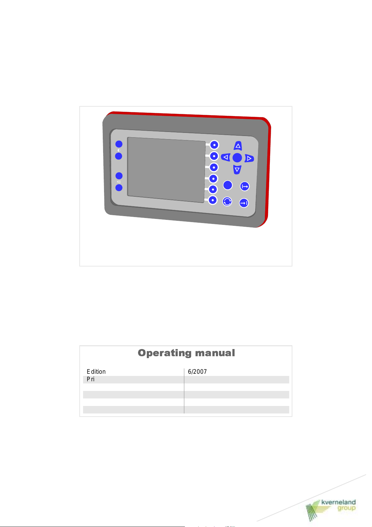
Focus 2 for
sowing machines
Operating manual
Edition 6/2007
Printing 10.2007
Language EN
For software from 1.03
For hardware version from –
Article number AC 758971

Identification of the machine
Your dealer will requi re certain information about your machine to be able to help you as quickly as possible.
Please enter the following data.
Designation
Operating width
Weight
Machine number
Accessories
Address of dealer
Focus 2
Manufacturer's address
Kverneland Group Soest GmbH
Coesterweg 42
D-59 494 Soest
Telephone +49 (0)2921 / 974-0
Copyright and exploitation rights for this document belong to Kverneland Soest GmbH, Germany. Copies, transfer into other m edia, tran slati ons
or the use of excerpts or parts are forbidden without express permission from Kverneland. All rights reserved. The contents of this operating manual may be changed without giving prior notice. We reserve the right to make technical changes.

Table of contents
To begin with ...................................................4
Safety................................................................5
Becoming familiar with the machine.............6
Area of use of the device 6
Features 7
An overview of the device 8
Technical data 10
functions 10
Delivery and assembly/installation..............11
Checking the scope of delivery 11
Assembly 11
Connecting up the machine .........................12
Safety 12
Connecting the Focus 2 12
Operation........................................................13
Switching on 13
Opening screen 13
Information screen 17
Table of contents
Storage...........................................................35
Removal 35
Storage 35
Removing faults.............................................36
Disposal..........................................................38
The EC Conformity Declaration ...................39
according to EC Directive
98/37/EC 39
Index...............................................................40
3
To begin with
To begin with
Target group for this
operating manual
Instruction
Meaning of the sym-
bols
This operating manual is designed for us e by tr ained a gricultu rists an d
persons who are otherwi se qualified t o work in agri culture and who have been instructed on how to use this machine.
For your safety
Please familiarise yourself with the contents of this operating manual
before commissioning or assembling the machine. You will obtain optimal operating results and will also be working more safely.
As an employer
All personnel are to be instructed on a regul ar basis , but at least onc e
a year, according to the provisions of Employer's Liability Insurance
Association Article 1. Untrained or unauthorised persons must not be
allowed to use the m achine.
You will receive instruction fr om your deal er about ho w to oper at e and
take care of the machine.
We have used various symbols in the text to make the presentation
clearer. They are described below:
• A point stands next to enumerations
> A triangle is located before activities which you should undertake
→ An arrow indicates cross- references to other texts
We also use pictograms which will aid you in findi ng text passages:
N
OTE
The word "Note“ refers to tips and guideli nes concerning operating th e
machine.
The screwdriver sym bol announces tips concerni ng assembly or setting up work.
The hazard warning triangle refers to important safety instructions.
Nonobservance of these can lead to the following consequences:
• General malfunctioning of the machine
• Damage to the machine
• Injury to persons or accidents.
0
4
A star indicates examples which serve better understanding.

Safety
Checking the cables
Check cables before connecting them up and replace damaged cables. Damaged cables can lead to damage occurring to the machine
or to uncontrolled behaviour of the electronic control system.
Observe the prescribed temperature range
The device will only oper ate reliabl y within the pr escribed t emperature
range. Higher or lower t emperatures can l ead to uncontrolled behaviour of the electronic control system.
Behaviour as a result of malfunctions
Please stop working immedi ately if a malfunction occurs and switch of f
the device. Look at the chapter "Removing faults"»Removing faults«
and remove the fault. Inform our Customer Service Department if the
fault cannot be removed. Continuing to operate a faulty machine can
lead to major damage to the machine and errors in the seed deposit.
Maintenance work
Disconnect from the power supply to the machine before conducting
maintenance work. It may prove impossible otherwise to exclude damaging the device.
Safety
5
Becoming familiar with the machine
Area of use of the device
Intended use
Mode of operati on
Notes on the ISOBUS
standard
This section contains gener al i nformation on your machine as well as
information on:
Becoming familiar with th e machine
• Area of use
• Features
• Technical data and
• functions
The device is designed for use in agriculture. It controls agricultural
machinery and devices.
The device is designed to be used in connection with agricultural machinery and devices to control and monitor their functions. Any other
use is forbidden.
A travel sensor determines the route and dis tance travelled and a job
computer calculates the current speed. The rotary speed necessary
for the drive motor on the metering devic e is deter mined from the current speed and the pres et setpoin t for the amount of seed per hectar e.
Not all of the display device f eatures are standardised in the ISOBUS
standard. It may therefore be the c ase that a termi nal made by another
manufacturer has more or fewer selection keys. Depending on the
number and arrangement of the selection keys, the symbols identifying their assignment may be in different positions. The description
here applies only to the device specified on the title page.
The Focus 2 terminal does not comply with the ISOBUS standard. It
can only be used in conjunction with machines made by the Kverneland Group.
6
Becoming familiar with the machine
Features
Terminal [+]
Switched power ca-
ble [+]
Job compute r
Control and monitori ng are possibl e using a termi nal i n connecti on with further components on the respective machine which can be matched to the type of machine being used. The overall system consists
of the components
• Terminal [+]
• Switched power cable [+]
• Job computer
• Travel sensor
• and possibly other sensor or act ors
The individual functions ar e shown graphical ly in the display. We have
dispensed with text as far as possible.
The terminal serves to enter and monitor sowing val ues.
The switched power cable is t he int erf ace between the tract or and th e
machine. Some tractors have already been fitted out with this interface
at the works. Please have the switched power cable installed on your
tractor by the dealer or a specialist workshop if this is not the case.
The job computer cr eates the connection between terminal, sensors
and actors. It is mounted on the seed sowing machine.
Travel sensor
A travel sensor determines the distance travelled.
7
Becoming familiar with the machine
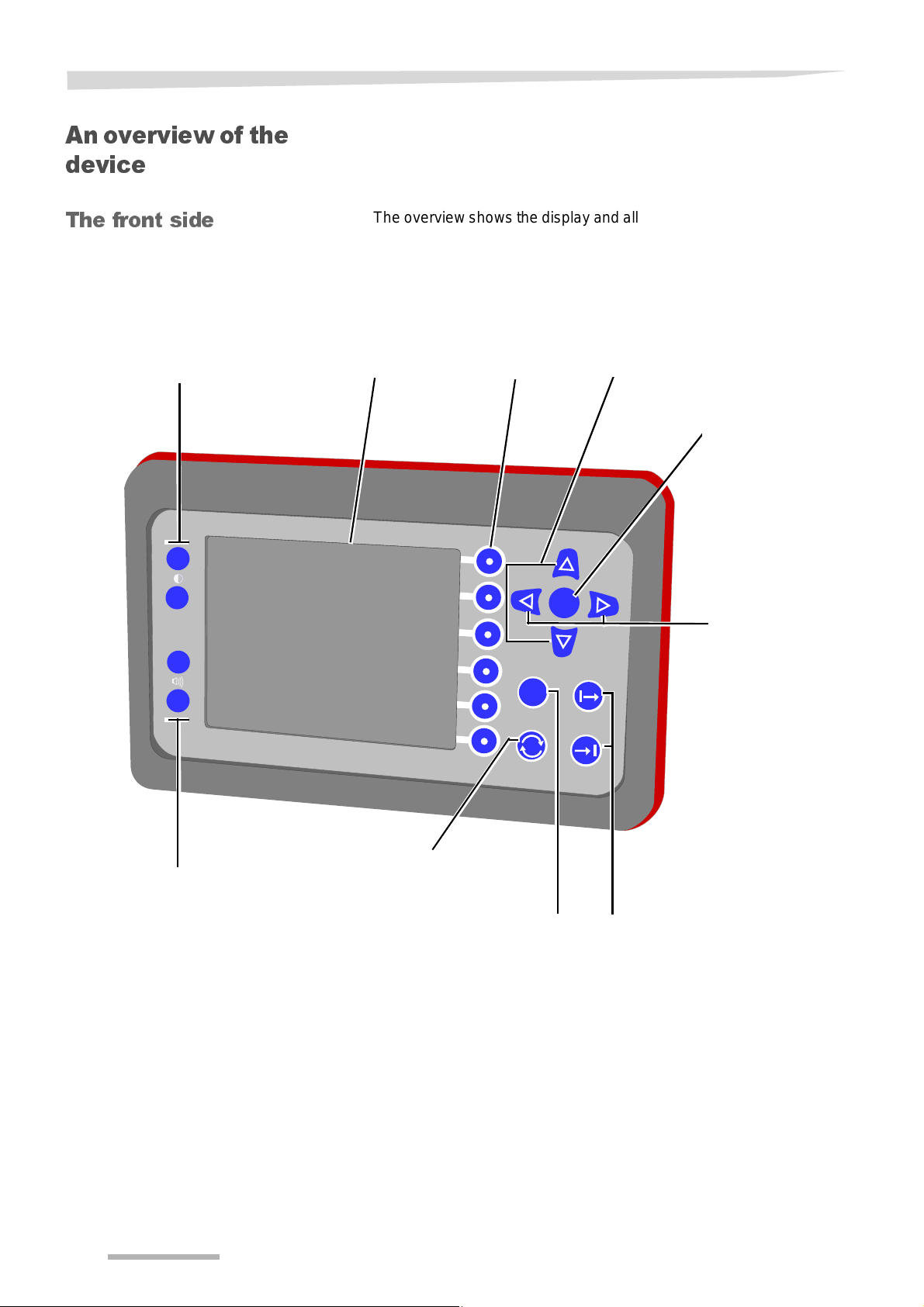
An overview of the device
The front side
Increase or reduce the contrast
+
–
+
The overview shows the display and all of key s which have each bee n
allocated a function.
Display
Selection keys
Increase or decrease
values
O
K
Confirmation of
entries
Selection of
data entry
fields
–
Increase or reduce the
volume
Switch to the previous screen or
to other connected machines
E
S
C
Resetting of
entries to their
original value
Keys without a
function
8
Becoming familiar with the machine
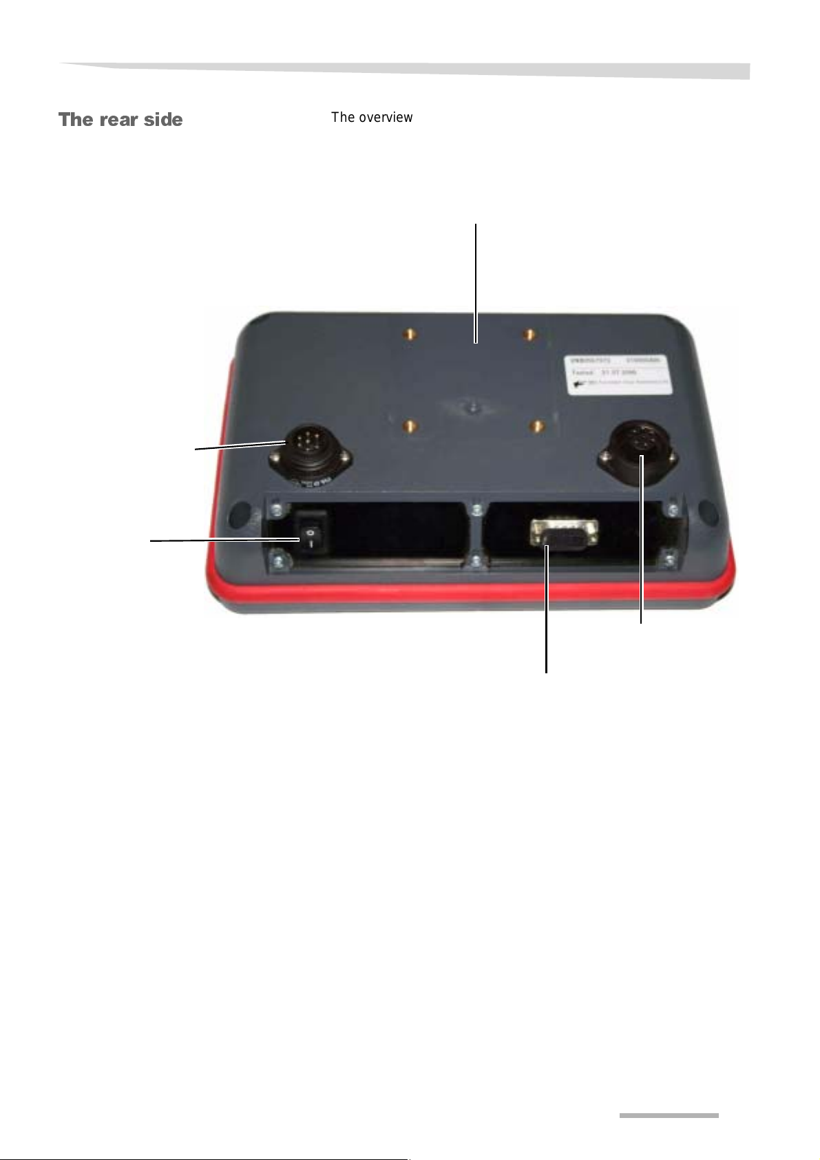
The rear side
Connection for the control cable from the job
computer
The overview shows all connections on the rear side.
Base for the bracket for
fixing devices
ON-OFF
switch
Connection for the
service technician
1. Connection for radar
or speed sensor on the
tractor
2. Outlet for CAN BUS
9
Becoming familiar with the machine
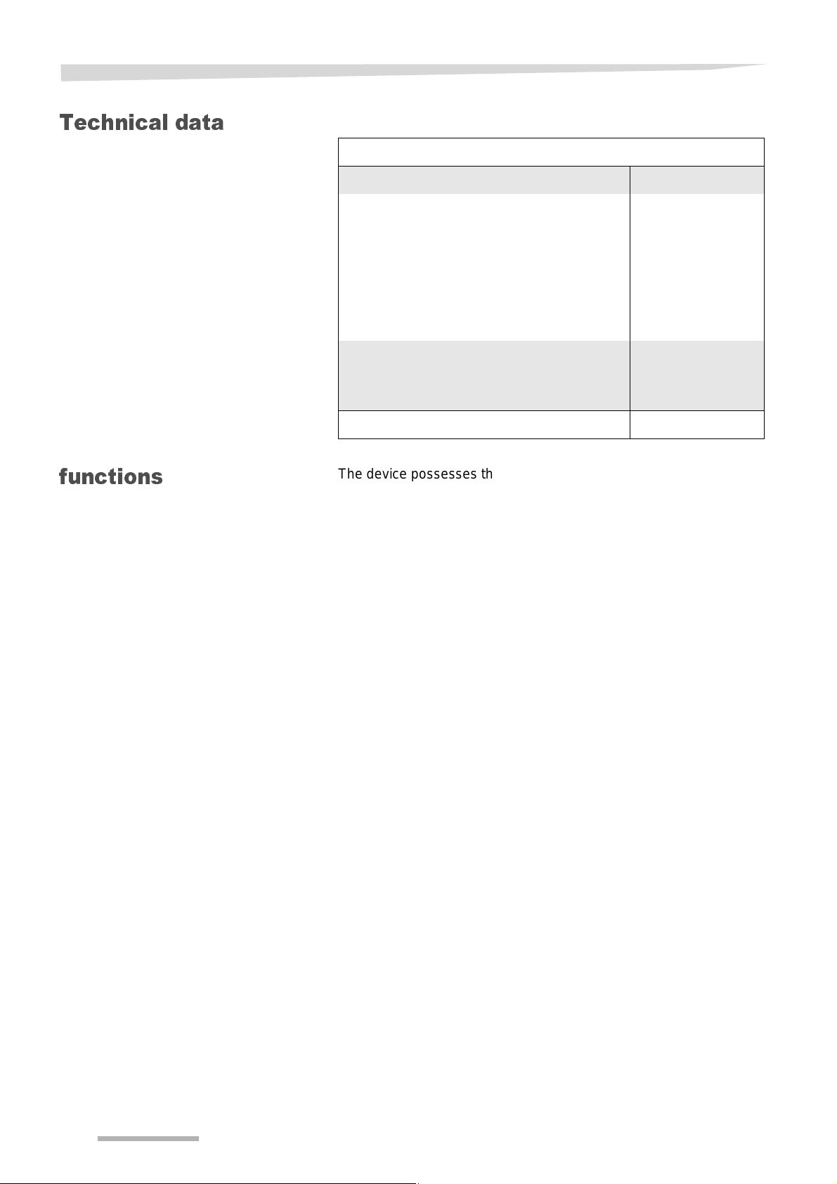
Technical data
Focus 2
Power supply (V) DC 12-14
Safety fus e (A)
• Switched power cable
• Central printed circuit board
• Battery cable for power supply to the te r-
minal
• Battery cable for power supply to the mo-
tors
Protective classes
• Terminal
• Control unit
Temperature range (°C) -10 to +50
25
1x 30 A; 1x 5 A
25
60
IP 54
IP 65
functions
The device possesses the following functi ons:
• Regulation of the amount of seed
• Automatic tramlining control system
• Automatic tramline marking [+]
• Determination of the processed area per task
• Determination of the overall area processed
• Indication of speed
• Determination of the operating time
• Adjustment to partial widths (of a trenc h)
10
Delivery and assembly/installation
Delivery and assembly/ installation
Checking the scope of delivery
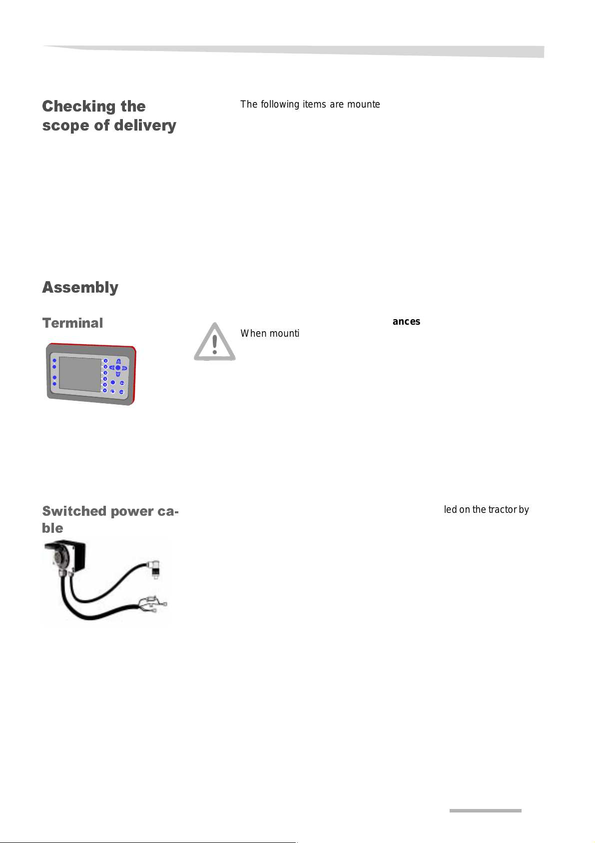
Assembly
Terminal
+
–
+
–
K
O
S
E
C
The following items are mounted on the seed sowing machine at the
works:
• Job computer
• Travel sensor
The following can be supplied as accessories:
• Switched power cable
• Terminal
N
OTE
A claim should be made without delay to your dealer, the importer or
the manufacturer for any missing parts or parts which have been damaged during transport.
Maintain defined minimum clearances
When mounting the terminals a minimum distance of one metre must
be maintained from mobile telephones, radios or radio antennae. Unforeseen malfunctions could occu r if the distance is too small.
Ensuring a good view
The terminal must not limit the oper ator's v iew. Access to all functions
of the tractor must remain unimpaired. Accidents can arise if the operator's view is blocked or there are impairments to operating tractor
functions.
Switched power ca-
ble
> The terminal should be mounted on the tractor in such a way that
you can easily read the display and can easily reached all operating keys.
The switched power cable should only be i nstalled on the tractor by th e
dealer or a specialist workshop.
11
Connecting up the machine
Safety
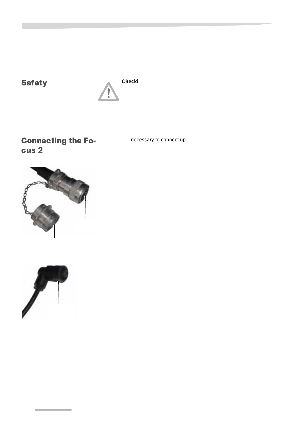
Connecting the Fo-
cus 2
Prerequisites for connecti ng up the machine are:
Connecting up the mach ine
• The machine is coupled to the tractor.
• All components are installed in an orderly manner.
• All cables and plugs are in perfect condition.
Checking the cables
Check cables before connecting them up and replace damaged cables. Damaged cables can trigger unexpected malf unctions.
Observe the prescribed temperature range
The device will only oper ate reliabl y within the pr escribed t emperature
range. Higher or lower temperatures can trigger unexpected malfunctions.
It is necessary to connect up two cables to operate the Tellus.
• Cable from machine to switched power cable.
• Cable for control system to terminal
Cable from machine to switched power cable
> Remove dust cap from plug
> Connect plug to switched power cable
> Secure plug
Dust cap
Plug
Plug
Cable for control system to terminal
> Connect cable to the rear of the terminal
> Secure plug
12
 Loading...