

Kverneland CLC Evo Wings, CLC Evo Instruction Manual

CLC Evo - CLC Evo Wings
Instructions
Edition 04/2014
Printing 1.2014
Language EN
From serial no. 009171
Execution Rigid/Folding
Reference. RF30115D

Identification of the machine
In order that your dealer may help as fast as possible, he needs a few indications regarding your machine.
Please provide this information below.
Description
Working width
Weight
Machine No.
Accessories
Dealer’s
address
CLC Evo - CLC Evo Wings
Manufacturer's
address
Kverneland Group Les Landes Génusson S.A.S.
9 rue du Poitou
F-85130 LES LANDES GENUSSON
Tel: +33 (0)2 51 64 13 00
The copyright and use (Copyright) are held by the Kverneland Group Les Landes Génusson SAS, France. Copying, transferring to other media,
translating or using even partially this text are illegal without Kverneland's written authorisation. All rights reserved. The content of these operating
instructions may be changed wit hout notice. Subject to technical changes.

Table of contents
Preamble ................................................... 4
Target group for this operating manual 4
Meaning of symbols 4
Safety ......................................................... 5
For your safety 5
Warning symbols 5
Safety rules 8
Other instructions 12
Getting to know the machine .................. 13
Scope of use of the machine 13
General description 14
Technical specifications 15
Rear accessory variants 20
Roller variants 21
Depth control wheel variants [+] 22
Option (other) [+] 22
Distribution of right and left deflectors 24
CLC Evo configurations 25
CLC Evo wings configurations 29
31
Table of contents
Control 58
Replacing the tines 61
Wear of the coulters 62
Disc wear 64
Skid wear on Actipack 65
Hydraulic diagram ..................................... 66
Guarantee ................................................... 67
Disposal of the machine ........................... 68
Metal parts 68
Tyres 68
Hydraulic oil 68
EC conformity declaration ........................ 69
In accordance with EC directive
2006/42/EC 69
In accordance with EC directive
2006/42/EC 70
Index ........................................................... 71
Delivery and assembly ............................. 32
Check on reception 32
Repositioning the tines 32
Installing the accessory or roller arms [+] 33
Attaching the rear accessory [+] 33
Attaching the roller [+] 33
Rear accessory configuration 34
Mounting the rear struts (folding machine) 36
Coupling .................................................... 38
Transport ................................................... 39
Safety 39
Commissioning ......................................... 42
Settings - Adaptability .............................. 43
Range of coulters 43
Range of deflectors 43
Settings ..................................................... 44
Step 1: working depth 44
Step 2: Adjusting the rear accessories 46
Actiflex roller 50
CLC folding lighting kit 50
Uncoupling the machine .......................... 51
Cleaning, maintenance and storage ....... 53
Cleaning 53
Maintenance 53
Storage 53
Maintenance .............................................. 54
For your safety 54
General remarks 55
Lubricating 56
3
Preamble
[+]
Preamble
Target group for this operating manual
Training
Meaning of symbols
This operating manual is intended for trained farmers and individuals
who are otherwise qualified to perform agricultural activities and who
have received training in the operation of this machinery.
For your safety
Study th e contents of this o perating manual carefully befo re assembly
or initial operation of the machine. In this way, performance and work
safety are optimised.
For the employer
All personnel are to be trained in the use of the machine regularly (at
least once a year) in accordance with employers' liability insurance
association guidelines. Untrained or unauthorised individuals are not
permitted to use this machine.
The retailer provides the user with instructions relating to the use and
maintenance of the machine.
In order to make this manual clea r and easy to read, we have u sed
various symbols. They are explained below:
• A dot precedes each item in a list.
A triangle indicates operating functions which must be performed.
→ An arrow indicates a cross-reference to other sections of this
manual.
We have also used pictograms to help you find instructions more
quickly:
N
OTE
The term “Note” indicates tips and notes on operation.
The screwdriver indicates tips for assembly or adjustments.
The warning triangle indicates importan t safety instructions. Failure to
observe these safety instructions can result in:
• Serious operational faults of the machinery;
• Damage to the machinery;
• Personal injury or accidents.
A star indicates examples that help to better understand the instruc-
tions.
A plus sign in square brackets indicates that the equipmen t is optional.
4
Safety
Safety
For your safety
Warning symbols
Meaning of symbols
In this chapter you will find the general safety instructions. Each
chapter of the operating manual contains additional specific safety
instructions, which are not described here. Please follow the safety
instructions
• in the interest of your own safety,
• in the interest of the safety of others,
• to ensure the safety of the machine.
Numerous risks can result from handling agricultural machines in the
wrong way . Therefor e, always work with special care and never under
pressure.
The employer should:
Inform personnel working with the machine of these safety instructions at regular intervals and according to statutory regulations.
On the machine you will find decals for your safety. These decals must
not be removed. When they are illegible or they no longer stick, order
new decals and affix them at the corresponding locations.
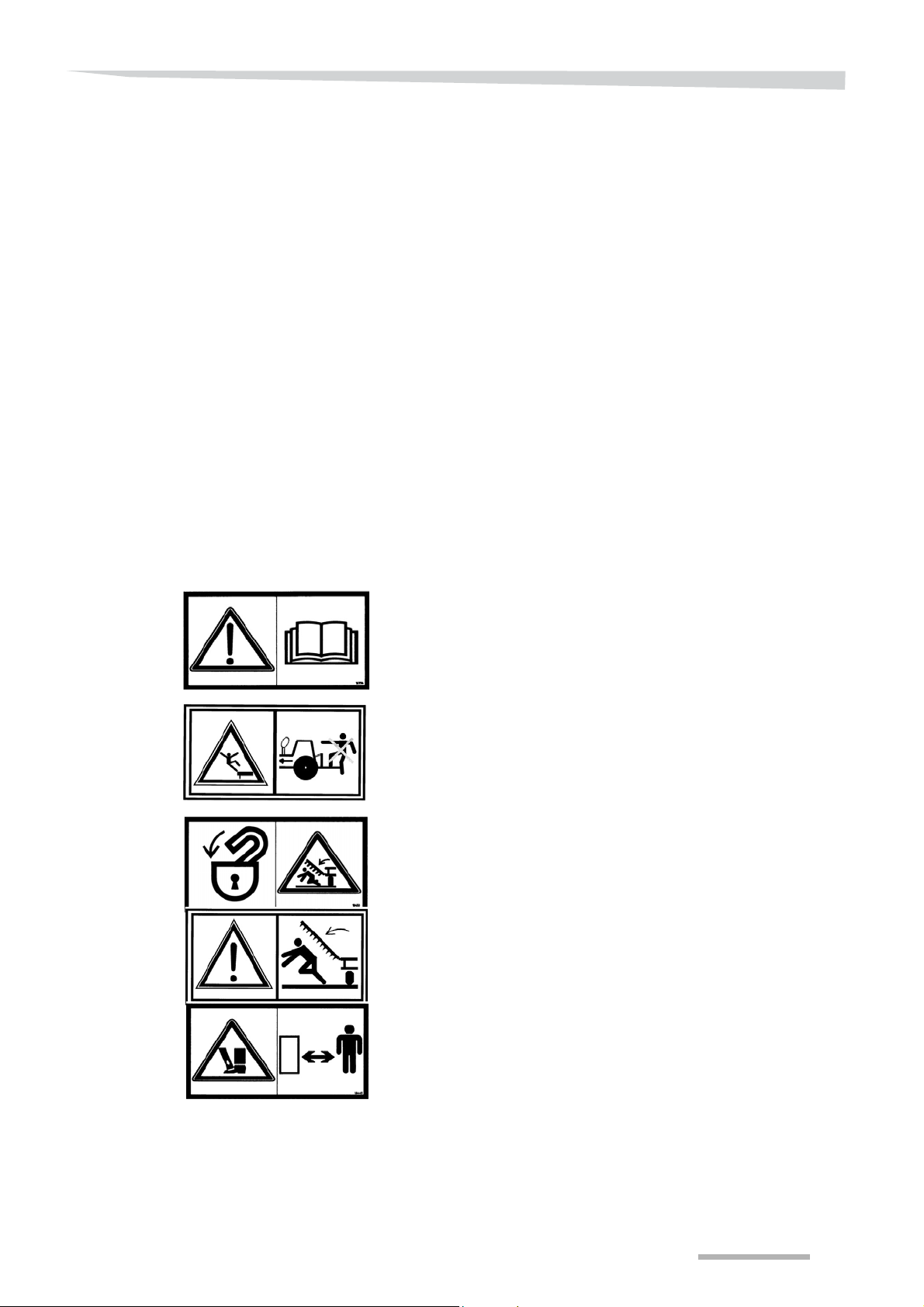
Read and comply with the manual and safety instructions before
starting up or carrying out any operations on the machine.
Carrying persons on the machine while in motion (in transit or at wo rk)
is strictly forbidden.
Risk of crushing by an articulated part of the machine. In stall the safety
devices provided and/or check the working order of the automatic
safety devices before entering a hazardous area.
Risk of crushing by an articulated part of the machine. In stall the safety
devices provided and/or check the working order of the automatic
safety devices before entering a hazardous area.
Risk of feet being crushed during machine adjustment. Keep a safe
distance from this part of the machine.
5
Safety
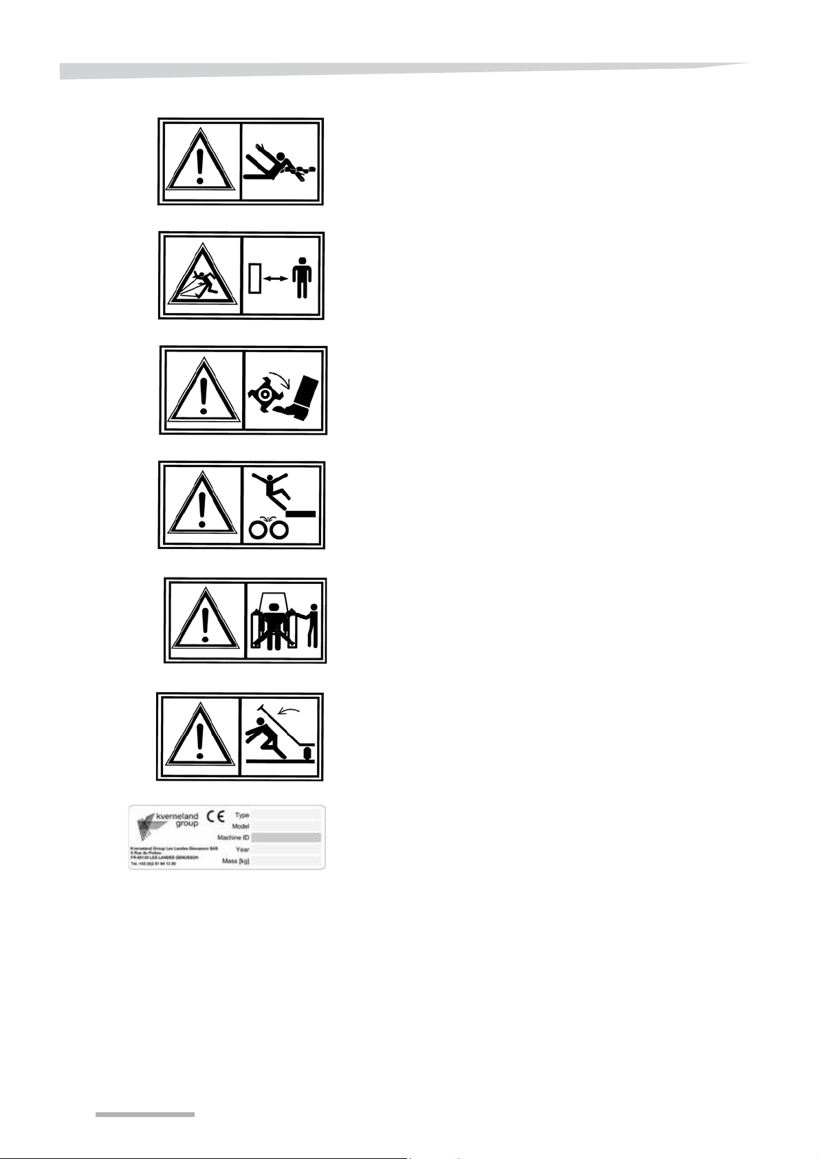
Risk of being caught by a rotating part of the machine (PTO shaft, for
example).
Risk of projection of stones and other materials. Keep a safe distance
from this part of the machine.
Risk of foot being severed by a rotating cutting implement. Keep a
safe distance from this part of the machine.
Risk of falling onto rotating roller implements. Keep a safe distance
from this part of the machine.
Risk of being crushed by the lower tractor lifting arms during hitching/
unhitching operations. Keep a safe distance from this part of the
machine.
Danger of being crushed by an articulated marker arm of the machine.
Install the safety devices provided and/or check the working order of
the automatic safety devices before entering a hazardous area.
EC type plate guaranteeing the conformity of the machine according
to directive 2006/42/EC and adapted to national legislations.
6
Meaning of symbols
Sticker
location on the
machine
specific to the Knock-on
accessory
Safety
Protection risk against shard in case of striking the coulters with a
hammer.
(Two copies of this sticker is sent with the accessory. These stickers
are to be placed on the front left and back right beams of your
machine, please confer to the opposite diagram).
The coulters are made from treated steel.
During assembly or disassembly operations, never hit the coulters
directly with a hammer. You risk serious injury from flying shards or
breakage of parts. As a result, in order to avoid contact between two
hard and heavy pieces, use the special Knock-on tool.
WARNING
In the interest of safety measures,
A visor must be worn (in the absence of safety goggles).
Maximum facial protection is strongly recommended.
Gloves must be worn.
Generally, wearing adapted safety equipment is highly recomme nded
(safety shoes, protective clothing, helmet, etc.).
7

Safety
Safety rules
General recommendations
Before starting up, check that the machine is not endangering any
persons and that the protection and safety devices (e.g. guards,
hoods, warning labels, etc.) are in place and functional.
Before starting work, familiarise yourself with all the parts, controls
and functions of your machine. Once you have started working, it will
be too late!
Should an incident occur, stop the machine immediately and identify
the cause. Repairs should be carried out before starting up again.
No repair operations should be carried out on the machine un le ss:
• all measures have been taken to prevent the machine starting up
again accidentally (e.g. PTO and/or hydraulic hoses uncoupled,
tractor engine switched off),
• no chocks are placed under the frame to prevent the risk of the
frame descending,
• the vehicle is immobilised by appropriate means.
Before getting off the tractor, lower the machine onto the ground.
Apply the handbrake and remove the key from the ignition.
No one should pass between the tractor and the machine unless the
vehicle is immobilised (hand brake, chocks, etc.), the engine is
switched off and the ignition key removed.
Coupling
Follow the coupling instructions carefully:
• when manoeuvring, select the tractor's lowest possible forward
gear,
• there should be no-one between the tractor and the machine when
manoeuvring the tractor or lifting,
• the category of tractor hitch must be adapted to the hitching
characteristics of the machine,
• during coupling operations, the hydraulic controls of the tractor
should be in such a position that the linkage does not move while
handling,
• the hitch must be locked and should not unhook when lowered.
The distribution of masses is modified when the machine is coupled.
The maximum vehicle axle weight (see manufacturer's instructions)
must not be exceeded. If the un-ballasting of the front end is too large,
you must place additional masses to be able to maintain the steering
control of your tractor.
When coupling or uncoupling the implement, put any support
equipment provided in place to prevent the machine from becoming
unbalanced.
8

Safety
Driving on the road
Respect the highway code when travelling on public roads.
When cornering, beware of machine offset and weig ht transfer. Adapt
your speed.
In transit, secure the lower raising arms to prevent them from swinging
out.
The machine must not be moved outside the field or near people until
the fold-away extensions or the fold-away or tipping accessories (if
any) have been locked in the transport position.
In transit, the hydraulic hoses of the folding cylinders must be
disconnected to prevent them from unfolding accidentally.
On machines equipped with a transport carrier, secure the carrier
locking system before taking the machine onto the road.
When driving, the lift control should be positioned so as to prevent the
implement from being accidentally lowered.
Check that your hitch complies with local road safety legislation. If
necessary, you are responsible for fitting and testing transport
equipment (e.g. lighting, signals, guards, etc.) corresponding to the
characteristics of your tractor-machine assembly and the applicable
statutory requirements. Make sure that the dimensions of the machine
comply with the highway code.
Carrying persons on the working tool in transit is not allowed.
The brakes must be coupled up for all movements (no single-wheel
braking).
9

Safety
Use
Any tine that is abnormally blocked in the raised position may
suddenly return to its position and is therefore a source of serious
danger . Keep well clear and out of the return path of the tine. Once the
tine has returned to the low position, check that it is tight and does not
jam at any point.
Nobody must enter the range of movement of the folding extensions
or folding or tilting accessories (if present) if they have not been locked
by the system provided for that purpose. This system can be a chain,
pin, rigid rod or a controlled double valve.
Before starting up, make sure that the surrounding area is clear (no
children in the vicinity, etc.). Make certain that you have sufficient
visibility.
Any intervention on the machine is prohibited when the tractor is
moving. Keep a safety distance of at least 5 m from the machine in
motion (advance, movement of any part of th e machine, movement of
the tractor hitch).
For machines equipped with covering disks, edge disks, retractable
teeth, levelling boards, track erasers or any other accessory with a
vertical adjustment, it is recommended to maintain a safety distance
in case of an accidental fall of the equipment during its adjustment.
You are advised to wear safety shoes.
Serious injury and even death may result from contact with electric
power lines. T ake all precautio ns if you move or use the machine close
to power lines to avoid any contact.
When using on uneven ground, the tractor may deviate from its path
when it passing over holes, ditches or other irregularitie s in the terrain.
Only authorise a single person, the operator, on the tractor when the
tractor and machine are in operation.
10

Safety
Maintenance
No intervention must be made within the radius of the tractor - to ol unit
without the brakes or vehicle immobilisation system being engaged.
When changing parts on the machine, you are advised to be careful
with all parts with sharp edges or corners. We recommend that you
wear safety gear (helmet, safety shoes, gloves, etc.).
For machines equipped with folding extensions, make sure you follow
the instructions in this manual for assembly , disassembly and settings.
It is strictly forbidden to disassemble springs used as safety devices
for working parts. This operation must only be performed by
specialists.
Regularly check that bolts are tight, the tyre pressure and the
condition of the hydraulic circuit.
Before welding, disconnect the electric units (if there are any) and
disconnect the tractor alternator and battery if the tractor is hitched up.
Never direct the jet of high pressure cleaners directly onto the
bearings, the hydraulic pipes, electric units or other sensitive
components on the machine (risk of damage). The jet may bounce
back off some surfaces.
Power take-off
Follow the instructions of the cardan joint manufacturer.
Use only the cardan drive designed for the machine and equipped with
regulatory guards.
Start the transmission only after having ensured that there is no one
close to the machine.
The rotation speed of the power take-off must correspond to the
maximum rotation speed permissible by the machine.
11

Safety
Uncoupling the
machine
Hydraulic system
There is a higher risk of injury when uncoupling the machine from the
tractor! Therefore:
• Immobilise the tractor.
• Never stand between the tractor and the machine when coupling.
• Actuate the three-point power lift system slowly and carefully.
• Make sure that the machine is on flat and sufficiently stable
ground.
• Only disconnect hydraulic tubes if there is no pressure in the
tractor and machine hydraulic system.
The hydraulic system is pressurised.
When connecting the hydraulic system, make sure that the tractor
system and tool are not pressurised.
Connect the hydraulic system according to the instructions in the
user's handbook. Identify the connectors using a colour code to avoid
incorrect connections (the reversal of functions can cause accidents).
Before any intervention on the hydraulic system, block the folding
extensions and hydraulically controlled accessories in their rest
position, reduce the pressure and stop the tractor engine.
Other instructions
Following the instructions
In addition to the instructions listed above, always obey:
• Accident prevention regulations
• Generally recognised safety regulations, occupational health
requirements and road traffic regulations
• Remarks made in this operating manual
• instructions for use, maintenance and servicing.
12

Getting to know the machine
Getting to know the machine
Scope of use of the machine
This chapter contains general information about your machine as well
as information concerning the following points:
• Scope of use
• Features
• The description of groups and technical data
This machine has been designed solely for norm al agricultural use,
i.e. for cultivating farmland. Any other use or misuse, for example,
transportation, clearing or transmission of forces to another machine
is considered to be non compliant with the intended use.
The manufacturer and the specialised retailer decline all liability for
damage resulting from use that does not comply with the intended
use. The user is responsible for taking any ri sks.
Compliance with the conditions of use includes compliance with the
manufacturer's operating instructions.
The safety instructions (specified above) as well as the general rules
of safety, occupational health and travel on public roads must be
respected.
Modifications to the machine made by the client or the use of spare
parts or accessories that are not from KVERNELAND will cancel the
manufacturer's liability for all damages resulting from this modification.
The company will not be held liable for damage resulting from
erroneous settings, choice of equipment, seed, fertilizer, treatments or
farming strategy or for any other damage not directly related to the
machine.
13
Getting to know the machine
Accessory support arm
Frame 100 mm x100 mm
(4” x 4”)
Coupling of the upper link bar
Stubble cultivator module
Rear accessories
Couplings of the lower bars
General description
14

Getting to know the machine
Technical specifications
CLC EVO
Features Fixed models Folding models
Working width (m/ft) 2.50 (8’2”) 3.00 (9’10”) 3.50 (11’6”) 4.00 (13’1”) 4.00 (13’1”) 4.50 (14’9”) 5.00 (16’5”)
Transportation
width (m/ft)
Number of rows 2
Type of tines CLC with NS spring blade safety device or bolted safety device
Number of tines
Spacing/W orking
width (m)
Clearance under
the frame (mm)
Min./max. power
Lighting and
signalling kit
Coupling category
(upper link)
Coupling category
(on lifting arm)
Recommended tyre
pressure (bar)
2.50
(8’2”) 3.00 (9’10”) 3.50 (11’6”) 4.00 (13’1”) 2.85 (9’4”)
9
(265)/2.50m
(101/2”)/8’2”
65 / 210hp
48/154 kW
11
(265)/3.00m
(101/2”)/9’10”
80 / 240hp
59/177 kW
Cat II / III Cat III
Cat II / III Cat III
6 bars / 87 psi 3.9 bars / 57 psi
13
(265)/3.50m
(101/2”)/11’6”
95 / 270hp
70/199 kW
15
(265)/4.00m
(101/2”)/13’1”
870
(341/4’’’)
1 10 / 300hp
81/221 kW
Option
13
(290)/4.00m
(111/2”)/13’1”
105 / 300hp
77/221 kW
15
(290)/4.50m
(111/2”)14’9”
120 / 325hp
88/239 kW
17
(290)/5.00m
(111/2”)/16’5”
135 / 350hp
99/257 kW
Stubble cultivator
module
• Frame 100 x100 (4” x 4”)
• Clearance under the frame 870mm (341/4”)
• CLC tine
• NS safety device with spring blade or bolts
• Spacing between tines 2 rows 265-290/101/2” - 111/2”
• Depth of up to 30cm (12”) with rear accessory or roller alone
• Depth of up to 40cm (16”) without rear accessory or with double
gang of discs
15
Getting to know the machine
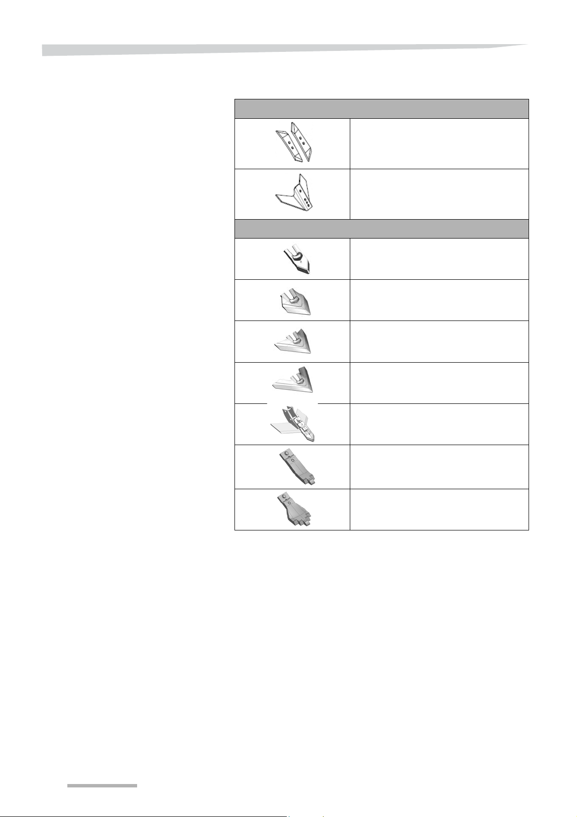
Coulter / blade
For CLC tines
Plough point 60mm (
Blade 300mm (12”)
For CLC tines (Knock-on)
Knock-on 80mm coulter (
Knock-on 150mm coulter (6”)
Knock-on 250mm coulter (10”)
Knock-on 320mm coulter (125/8”)
“Quantum”: Knock-on 80mm coulter
(
+ Blades 345mm (135/8”)
23/8”)
3”)
3”)
Carbide coulter 80mm Tiger
(3”)
Carbide coulter 150mm Tiger
(6”)
16
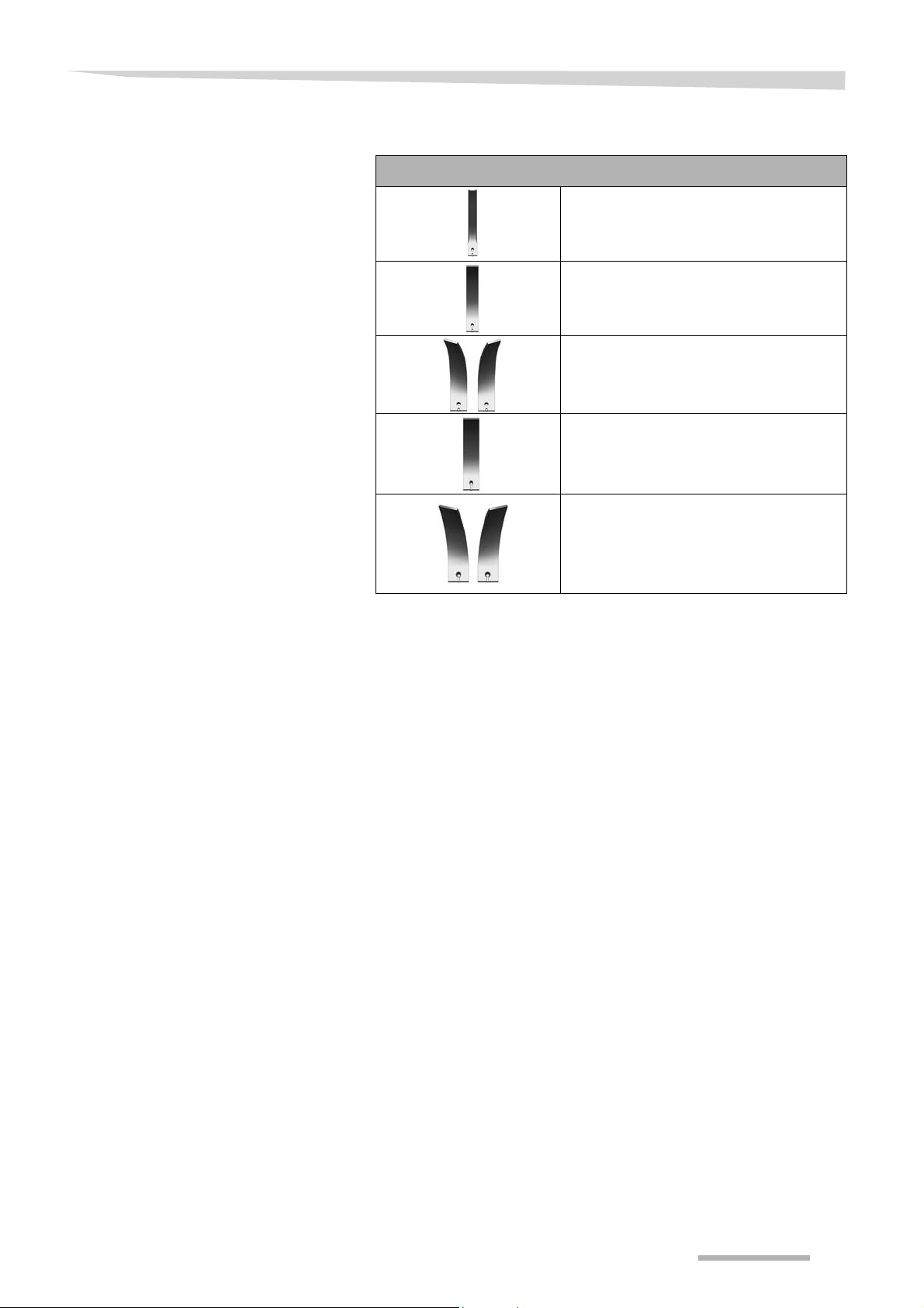
Tine protection /
Getting to know the machine
Deflectors
For CLC plates
65mm tine protector (2
80mm deflector
80mm twist deflector (3”)
(right and left)
100mm deflector
100mm twist deflector (4”)
(right and left)
5/8”)
(3”)
(4”)
17

Getting to know the machine
CLC EVO WINGS
Features Fixed models Folding models
Working width (m/ft) 3.00 (9’10”) 3.50 (11’6”) 4.00 (13’1”) 4.00 (13’1”) 5.00 (16’5”)
Transportation width
(m/ft)
Number of rows
Type of tines CLC with NS spring blade safety device or bolted safety device
Number of tines
Spacing/Working width
(m)
Clearance under the frame
(mm)
Min./max. power
Lighting and signalling kit Option
Coupling category (upper
link)
Coupling category (on
lifting arm)
Recommended tyre
pressure
(9’10”) 3.50 (11’6”) 4.00 (13’1”) 2.85 (9’4”)
3.00
2
7
(420)/3.00m
(165/8”)/9’10”
80 / 240 hp
59/177 kW
9
(390)/3.50m
(153/8”)/11’6”
95 / 270 hp
70/199 kW
Cat II / III Cat III
Cat II / III Cat III
6 bars / 87 psi 3.9 bars / 57 psi
11
(360)/4.00m
(14”)/13’1”
1/4”)
870(34
110 / 300 hp
81/221 kW
11
(360)/4.00m
(14”)/13’1”
105 / 300 hp
77/221 kW
13
(370)/5.00m
(145/8”)/16’5”
135 / 350 hp
99/257 kW
Stubble cultivator
module
• Frame 100 x100 (4” x 4”)
• Clearance under the frame 870mm (341/4”)
• CLC tine
• NS safety device with spring blade or bolts
• Spacing between tines 2 rows 350-420 (136/8” - 165/8”)
18
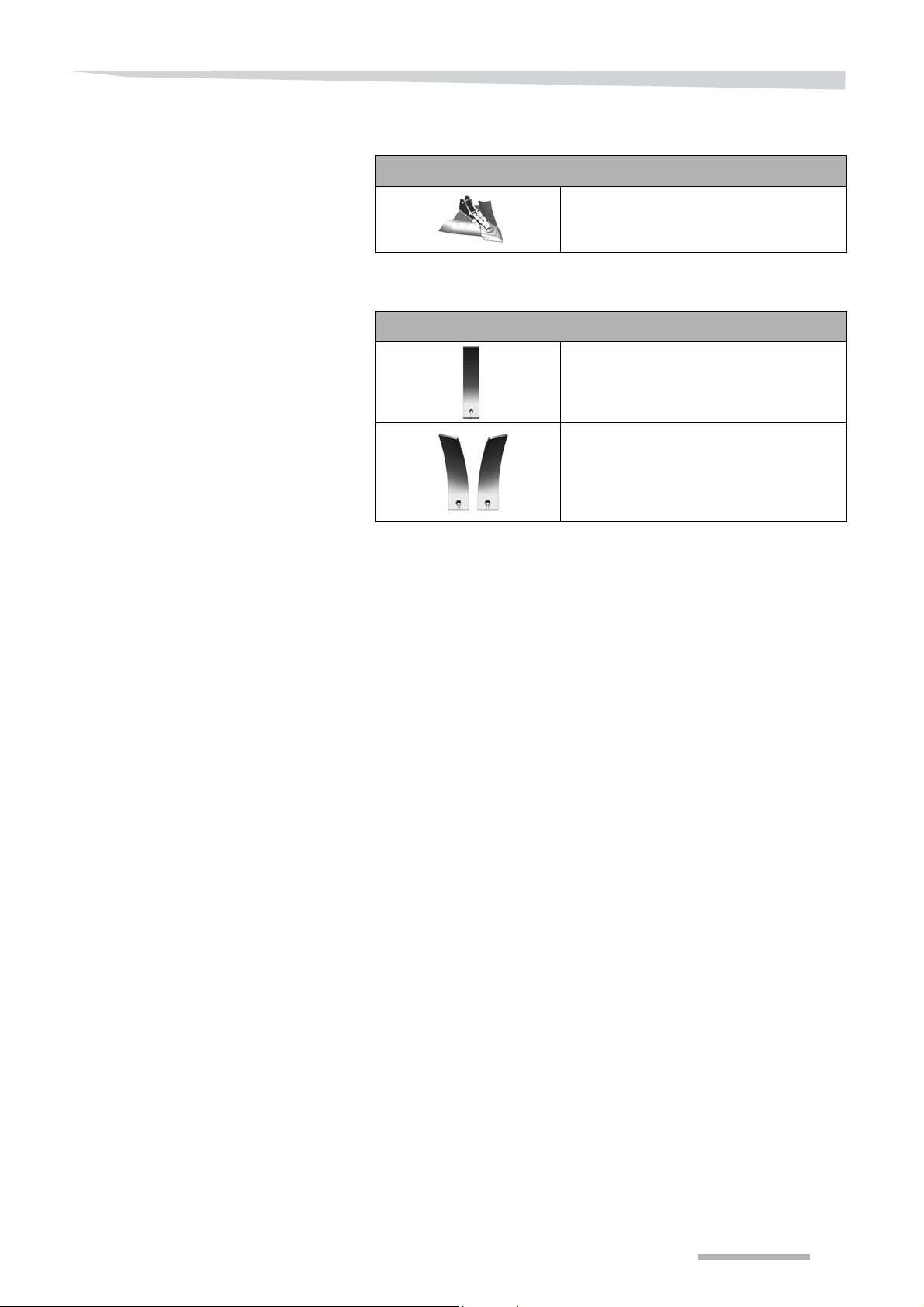
Coulter / blade
Getting to know the machine
For CLC tines (Knock-on)
Tine protection /
Deflectors
Knock-on 150mm coulter (
+ Blades 470mm (181/2”)
For CLC plates
100mm deflector (
100mm twist deflector (
(right and left)
6”)
4’’)
4’’)
19

Getting to know the machine
Rear accessory variants
CLC Evo
4 possible configurations, of which 3 are mounted on
parallelograms
Combi-disc (gang of discs + roller) [+]
• Depth control: by roller
• Levelling/ dispersal: by gang of discs
• Setting the depth of the gang of discs:
--> movement by hydraulic jack
--> depth control adjustment using plastic chocks
• Compaction: rear roller
Tandem disc (double gang of discs) [+]
• Depth control: by front wheels
• Levelling/ dispersal: by two gangs of discs
CLC Evo wings
CLC Evo + Evo wings
Hollow disc + roller [+]
• Depth control: by roller
• Levelling: by spading discs on rubber spring safety device
• Compaction: rear roller
Roller only (pivoting arm) [+]
• Depth control: by roller
• Compaction: rear roller
20

Roller variants
Getting to know the machine
Cage roller diameter 550mm (211/2”) [+]
• Compaction / light to medium soils
Flexipacker roller, diameter 58 5mm
(23”) [+]
• Compaction / light to medium soil without stones
Actipack roller diameter 560mm
(211/4”) [+]
• Compaction and dispersal / All soil types. This roller is also suited
to clayey and sticky soils
Actiring roller diameter 540mm
(211/4”) [+]
• Compaction and dispersal / All soil types (but limited by too many
stones)
Actiflex roller diameter 580mm (
Compaction and dispersal / All soil types.
Double tube roller / bar [+]
235/8”) [+]
• Dispersal, levelling and depth control / All soil types
21

Getting to know the machine
Depth control wheel variants [+]
Fixed cultivator: 6.00x9 wheel
Diameter 540 x 160 (
Folding cultivator: 10/80x12 wheel
Diameter 710 x 274 (
211/4” x 61/4”)
28” x 103/4”)
Option (other) [+]
Signalling and lighting [+]
All lights, reflectors, licence plates and signalling / warning panels
must be perfectly visible. If this is not possible, you must install lights
and a licence plate on the machine.
22
 Loading...