

Kverneland a-drill Operating Manual

Pneumatic seed drill
a-drill
Operating manual
Translation of the original operating manual
Issue 04/2018
Printing 02.2018
Language EN
From serial no. RFSDCxx006315
Execution Accessories
Reference RF31913

Identification of the machine
In order that your dealer may help as fast as possible. He needs a few indications regarding your machine.
Please provide this information below.
Description
Pneumatic seed drill a-drill
Working
width
Weight
Machine no.
Accessories
Reseller
address
Manufacturer
address
Kverneland Group Les Landes Génusson S.A.S.
9 Rue du Poitou
F-85130 LES LANDES GENUSSON
Tel: +33 (0)2 51 64 13 00
The copyright and use (Copyright) are held by the Kverneland Group Les Landes Génusson SAS, France. Copying, transfer to other
media,translation or even partial use of this text are unlawful without the written authorization from Kverneland. All rights reserved. The content of
these operating instructions may be changed without notice. Subject to technical changes.

Table of contents
Preamble ................................................... 4
Target group for this operating manual 4
Meaning of symbols 4
Safety ......................................................... 5
For your safety 5
Warning symbols 6
Safety regulations 7
Table of contents
Adjustments ............................................... 90
Using the seed drill with the box 3.2 90
Adjustments ............................................... 94
Using the seed drill with the box 5.2 94
Changing the flow during
operation 103
Trouble-shooting 108
Presentation of the accessory ................ 8
Conditions of use 8
General Description 9
Type of Seed drills 10
Technical specifications 10
Delivery and assembly ............................. 12
Rigid CLC 12
Delivery and assembly ............................. 22
Folding CLC 22
Delivery and assembly ............................. 28
Rigid Qualidisc 28
Delivery and assembly ............................. 34
Folding Qualidisc 34
Delivery and assembly ............................. 40
Rigid Qualidisc Farmer 40
Delivery and assembly ............................. 46
Folding Qualidisc Farmer 46
Delivery and assembly ............................. 54
Equipment available on
mounted machines 54
Maintenance ............................................... 110
For your safety 110
Guarantee ................................................... 111
Disposal of the tool ................................... 112
Metal parts 112
Hydraulic oil 112
Conformity declaration ............................. 113
In accordance with directive 2006/42/EC 113
Index ........................................................... 114
Delivery and assembly ............................. 56
Qualidisc T 56
Equipment available on Qualidisc T 63
Delivery and assembly ............................. 64
CTC 64
Delivery and assembly ............................. 70
Equipment available on CTC 70
Delivery and assembly ............................. 71
Mounting kit for hopper only 71
Installing the hydraulic blower 71
Adjusting the machine ............................. 72
Lifting sensor 72
Hydraulic blower 74
Seed drill adjustment ............................... 76
Distribution 76
Filling the seedbox ................................... 88
Safety 88
Folding CLC 88
Qualidisc and Qualidisc Farmer 89
3
Preamble
[+]
Preamble
Target group for this operating manual
Training
Meaning of symbols
This operating manual is intended for trained farmers and individuals
who are otherwise qualified to perform agricultural activities,
and who have received training in the operation of this machinery.
For your safety
Study the contents of this operating manual carefully before assembly
or initial operation of this machine.
In this way, performance and work safety are optimised.
For the employer
All personnel are to be regularly trained in the use of this machine.
Untrained or unauthorised individuals are not permitted to use this
machine.
The retailer provides the user with instructions relating to the use and
maintenance of the machine.
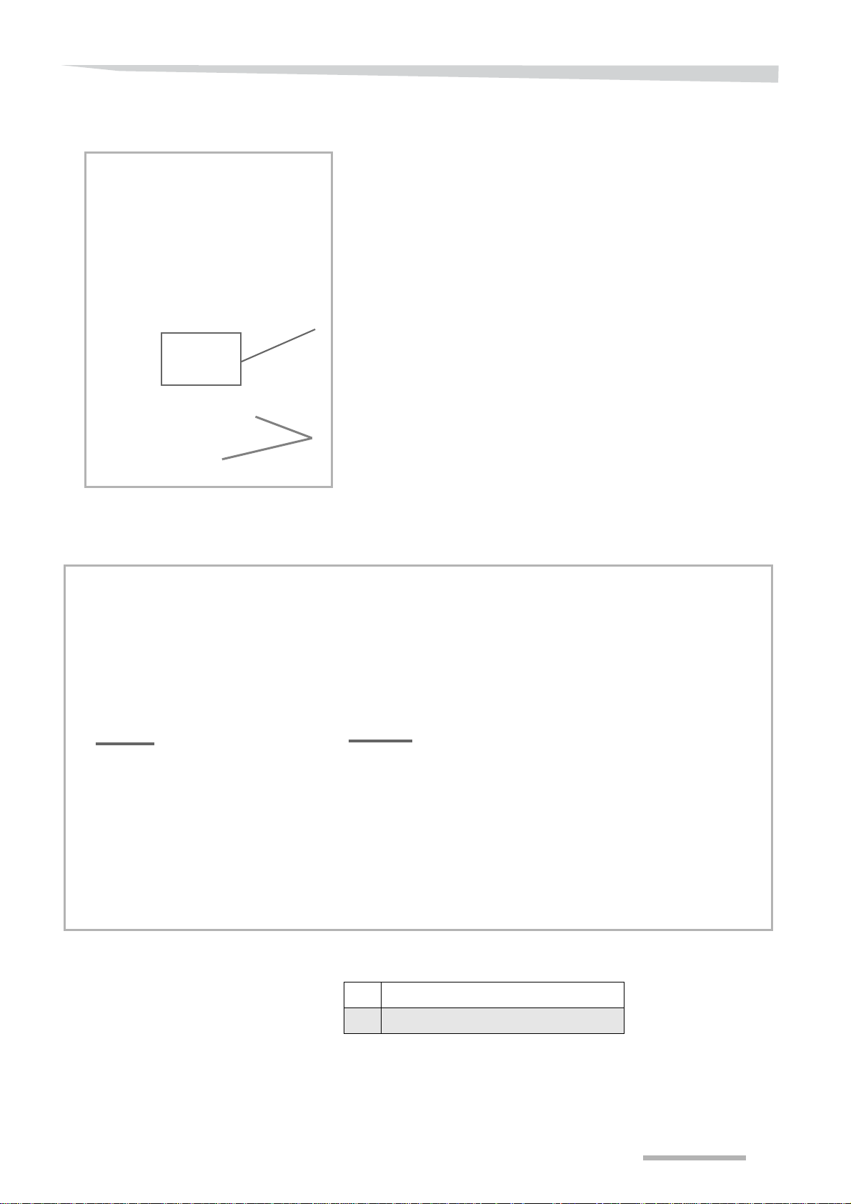
In order to make this manual clear and easy to read, we have used
various symbols. They are explained below:
• A dot precedes each item in a list.
A triangle indicates operating functions which must be performed.
→ An arrow indicates a cross-reference to other sections of this
manual.
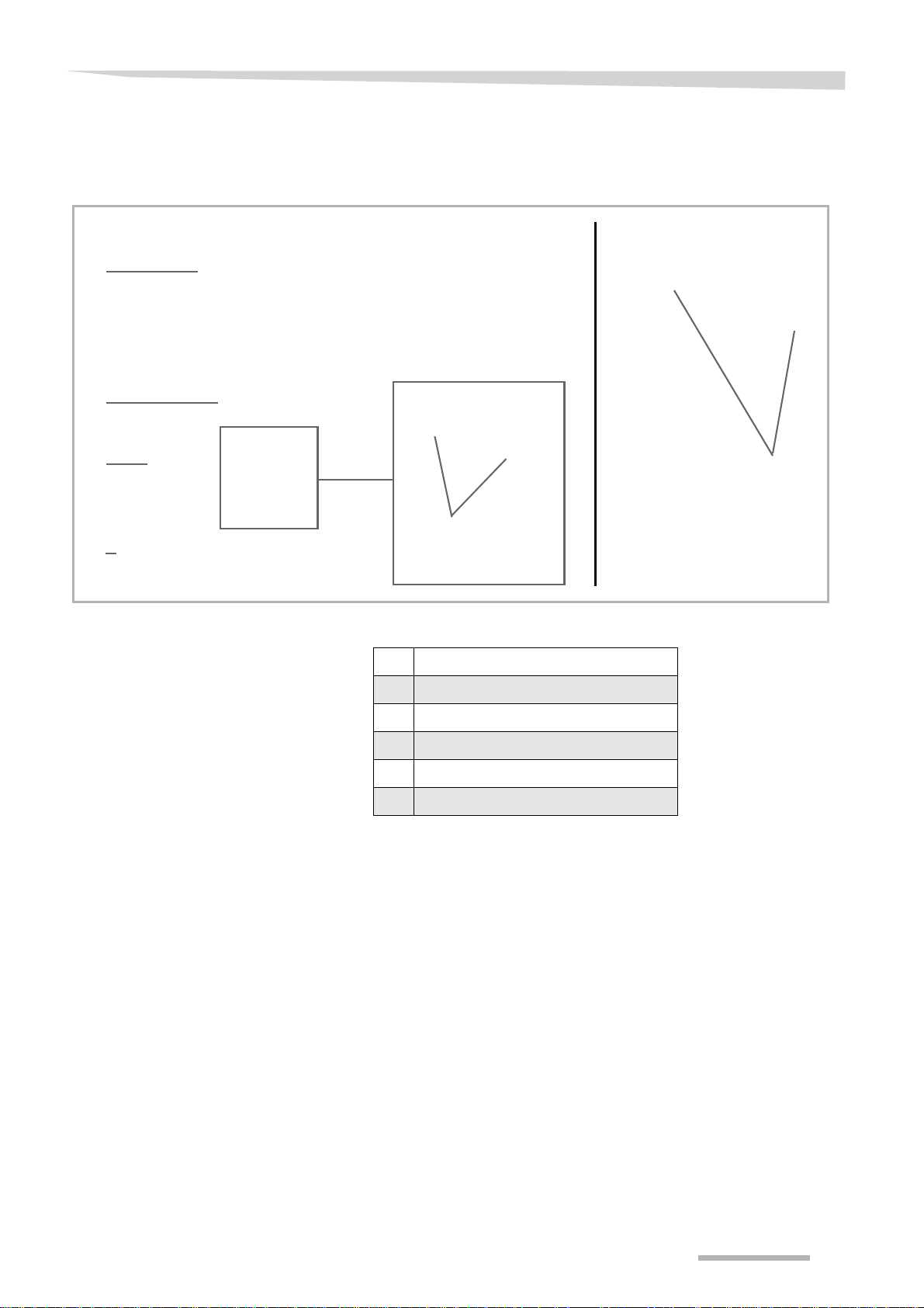
We have also used pictograms to help you find instructions more
quickly:
N
OTE
The term “Note” indicates tips and notes on operation.
The spanner indicates tips for assembly or adjustments.
The warning triangle indicates important safety instructions. Failure to
observe these safety instructions can result in:
• Serious operational faults of the machinery;
• Damage to the machinery;
• Personal injury or accidents.
A star indicates examples that help to better understand the instruc-
tions.
A plus sign in square brackets indicates that the equipment is optional.
4

Safety
Safety
For your safety
In this chapter, you will find the general safety instructions. The
different chapters in this operating manual include specific safety
instructions.
Please follow these safety instructions:
• in the interest of your own safety,
• in the interest of the safety of others,
• to ensure the safety of the machine.
Numerous risks can result from handling agricultural machines in the
wrong way. Therefore, always work with special care and never under
pressure.
For the employer:
Inform personnel working with the machine of these safety instructions at regular intervals and according to statutory regulations.
5
Safety
Warning symbols
Meaning of safety symbols
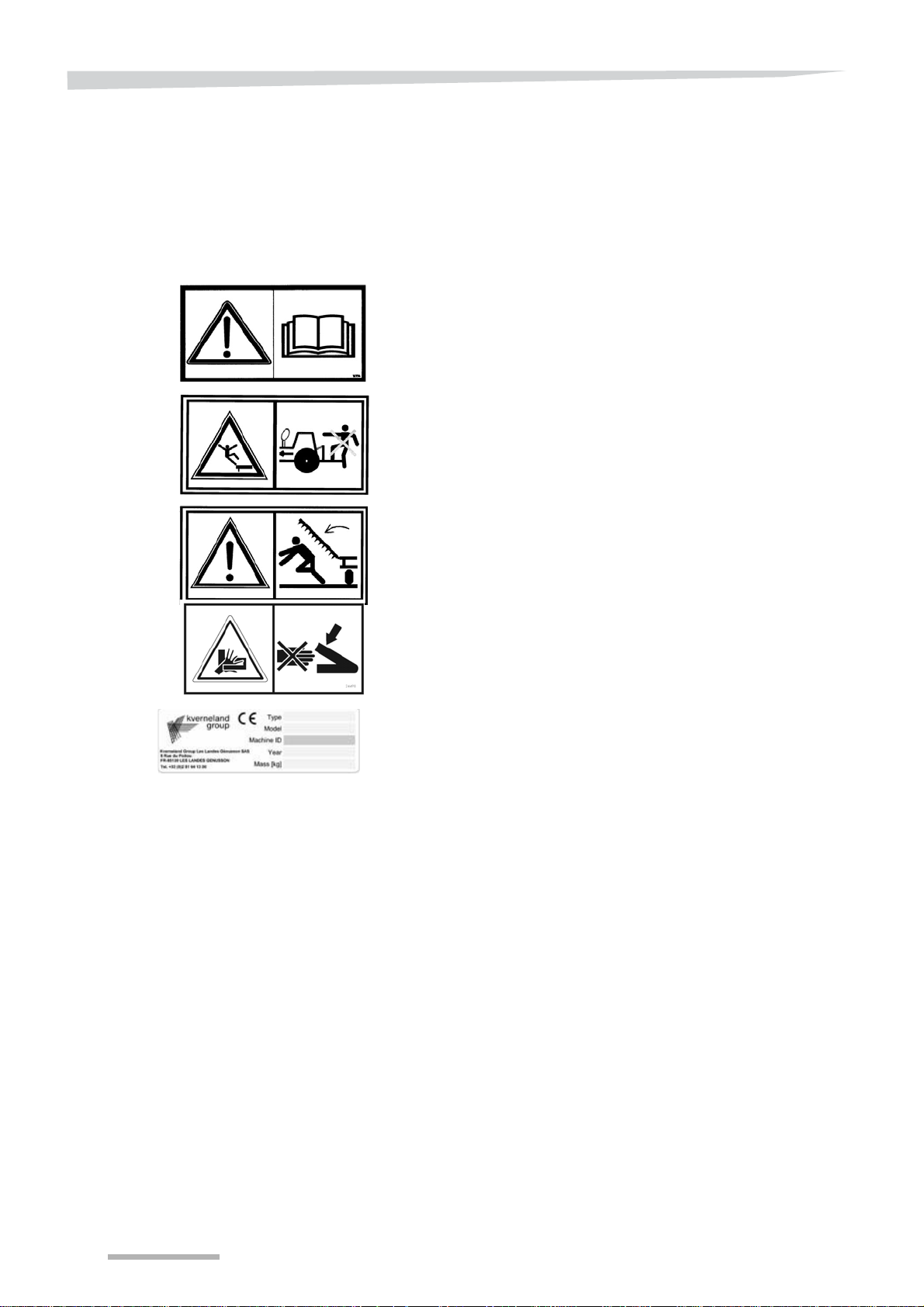
On this machine, you will find safety decals for user safety.
These decals must not be removed.
When these are illegible or they no longer stick, order new decals and
affix them at the corresponding locations.
Read and comply with the manual and safety instructions before
starting up or carrying out any operations on the machine.
Carrying persons on the machine while in motion (in transit or at work)
is strictly forbidden.
Risk of crushing by an articulated part of the machine. Install the safety
devices provided and/or check the working order of the automatic
safety devices before entering a hazardous area.
Risk of hands being pinched when adjusting the machine.
Please follow the adjustment instructions.
EC type plate guaranteeing the conformity of the machine according
to directive 2006/42/EC and adapted to national legislations.
6

Safety regulations
Safety
Maintenance
Hydraulic system
The brakes or vehicle immobilisation system must be engaged before
all interventions within the radius of the tractor - tool unit.
Wear safety gear (helmet, safety shoes, gloves, etc.) when changing
parts on the machine.
You are advised to be careful with all parts with sharp edges or
corners.
Before welding, disconnect the electric units and disconnect the
tractor alternator and battery.
Never direct the jet of high pressure cleaners directly onto the
bearings, the hydraulic hoses, electric units or other sensitive
components on the machine (risk of damage).
The jet may bounce back off some surfaces.
The hydraulic system is pressurised.
Before any intervention on the hydraulic system:
Block the folding extensions in their rest position.
Block the hydraulically controlled accessories in their rest
position.
Reduce the pressure.
Stop the tractor engine.
Identify the connectors using a colour code, as indicated in the user
manual, when intervening on the hydraulic system.
Incorrect connections and the reversal of functions could cause
serious injuries.
7

Presentation of the accessory
Presentation of the accessory
Conditions of use
This chapter contains general information about your tool as well as
information concerning the following points:
• Scope of use.
• Characteristics.
• The description of groups and technical data.
This tool has been designed solely for normal agricultural use, i.e. for
cultivating farmland. Any other use or misuse, for example,
transportation, clearing or transmission of forces to another machine
is considered to be non compliant with the intended use.
The manufacturer and the specialised retailer decline all liability for
damage resulting from use that does not comply with the intended
use. The user is responsible for all risks.
Compliance with the conditions of use includes compliance with the
manufacturer's operating instructions.
The safety instructions (specified below) as well as the general safety,
occupational health and road traffic regulations.
Modifications to the tool made by the client or the use of spare parts
or accessories that are not from KVERNELAND will cancel the
manufacturer's liability for all damages resulting from the modification.
The company will not be held liable for damage resulting from
erroneous settings, choice of equipment, seed, fertilizer, treatments or
farming strategy or for any other damage not directly related to the
machine.
8
General
A
B
C
D
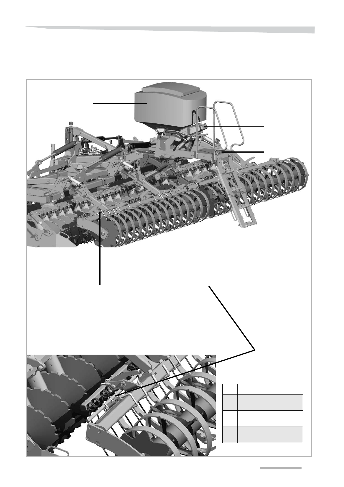
Description
Presentation of the accessory
A Hopper (200 or 500 l)
B Walkway (access filling and
settings)
C Blower (electrical or
hydraulic)
D Spreader rail (in front of the
roller)
9
Presentation of the accessory
Type of Seed drills
The a-drill pneumatic seed drills are distribution seed drills by fixed
grooved rotors.
s
The seed drill does not contain sowing element
carried out by 8 spreaders.
The flow adjustment is by variation in the gr
rotors are available. A support blower ensures the transportation of
seeds from the distributor to the spreaders.
pneumatic seed drills are available
The
in several versions :
, broadcast sowing is
oo
ved rotor speed, 8
• Hopper volume 200 l or 500 l
• Control box :
• Version 3.2 (manual flow adjustment)
• Version 5.2 (flow proportional to progression)
• Electrical or hydraulic blower on mounted machine, hydraulic on
trailed machine.
The box 5.2 provides the following additional services :
• End of field sensor (automatic stop and restart)
• EFPP (Electronic flow proportional to progression) by radar sensor
or ISO 7 terminal connector.
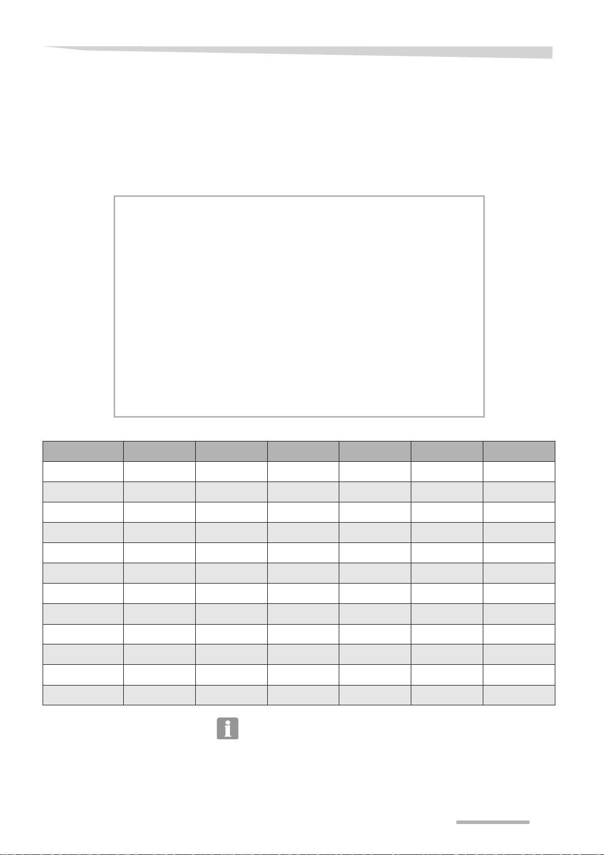
Technical specifications
Model
Weight of seed drill only
Dimensions (L x D x H)
Electrical supply
70 x 88 x 100 cm 80 x 122 x 117 cm
271/2” x 345/8” x 395/8” 311/2” x 48” x 46”
To have these two functions simultaneously, the box 5.2 is equipped
with a branch cable, that provides 2 x 12 terminal connectors.
200 L 500 L
52.83 gallons 132.10 gallons
60 Kg 100 Kg
132.30 lbs 220.5 lbs
12 V, 25 A
Hydraulic supply
10
Maximum pressure : 200 bar (2900.76 psi)
Maximum flow: 80 L/min (21.13 gallons/min)
Dimensions (L x D x H): 400 x 460 x 270 mm (15
3/4” x 18” x 105/8”)
Presentation of the accessory
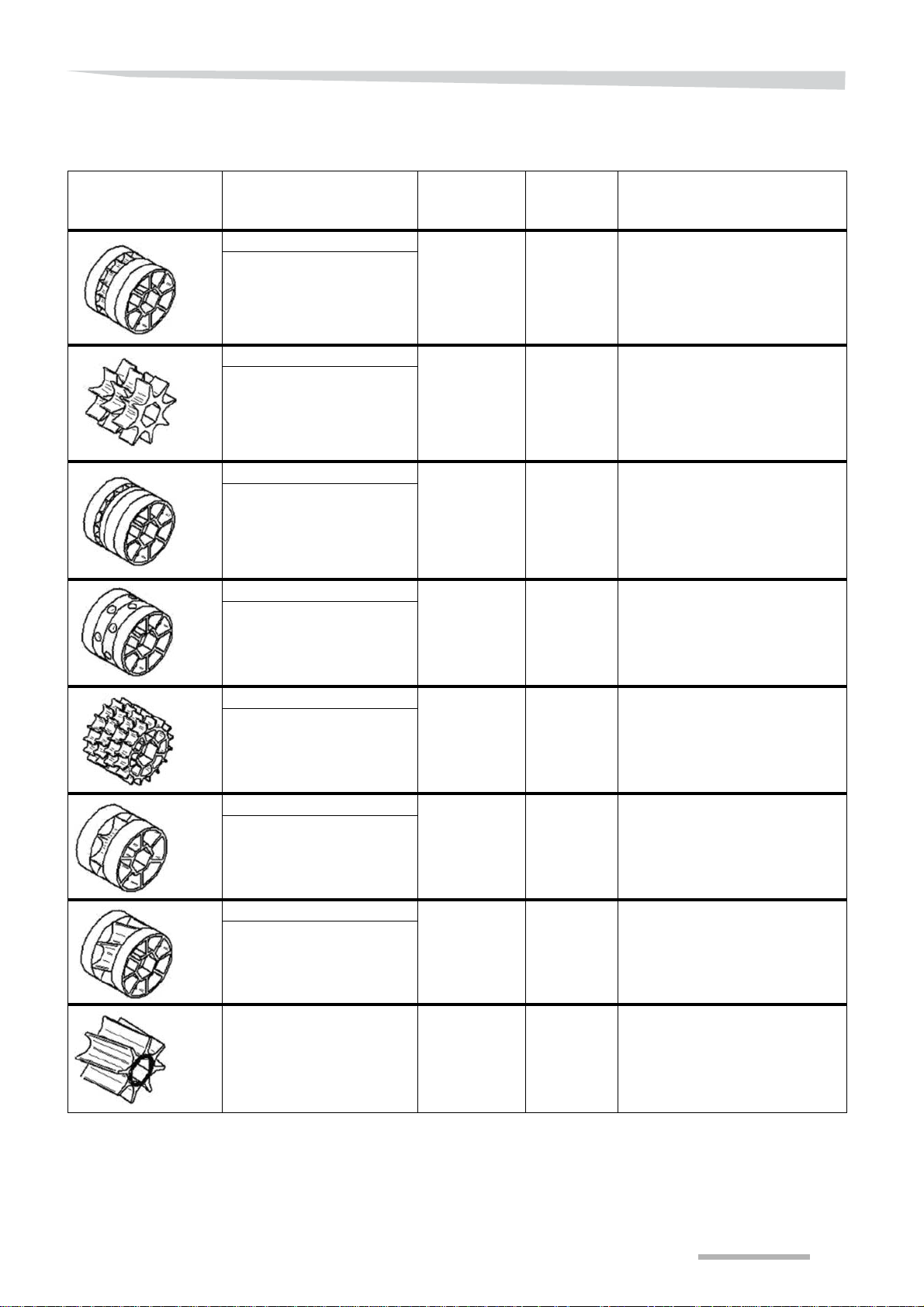
8 grooved distribution rotors are available :
Rotor Type of rotor Reference
fb-f-fb-fb
fine dummy
fine
fine dummy
fine dummy
GGG
Coarse
Coarse
Coarse
fb-ef-eb-fb-fb
fine dummy
extra fine
extra fine dummy
fine dummy
fine dummy
fb-efv-efv-fb
fine dummy
extra fine honeycomb
extra fine honeycomb
fine dummy
ffff
fine
fine
fine
fine
GB-G-GB
Coarse dummy
Coarse
Coarse dummy
RF32066
RF32061
RF32067
RF32209
A135122830
A135132030
Series /
option
Standard
equipment
Standard
equipment
Optional
equipment
Optional
equipment
Optional
equipment
Optional
equipment
Application
Fine grooves:
Sowing of small seeds or small
quantities.
Eg: mustard, rapeseed, clover,
phacelia, slug pellets, etc.
Large grooves:
Sowing of cereals.
Eg: mix of grasses, rye, barley,
wheat, oats, etc.
Very fine grooves:
Sowing of very small seeds or
very small quantities.
Eg: clover, poppy, rapeseed,
mustard, etc.
Fine honeycomb grooves:
Sowing of small seeds or small
quantities.
Eg: radish, mustard, etc.
Fine grooves:
Sowing of small seeds or small
quantities.
Eg: grass, wheat, barley, radish,
etc,
Coarse grooves:
Sowing of large seeds or large
quantities.
Eg: mix of grasses, rye, barley,
wheat, oats, etc.
fb-Flex20-fb
fine dummy
Flex20
fine dummy
Flex40 RF31432
A135002130
Optional
equipment
Optional
equipment
Flexible distribution wheel:
Sowing of very large seeds and
fertilizer.
G: fertilizer, peas and vetches.
E
Flexible distribution wheel:
Sowing of very large seeds and
fertilizer.
G: fertilizer, peas and vetches.
E
11

Delivery and assembly
Delivery and assembly
Rigid CLC
Mounting the support
and the hopper
Task description
There are two types of mountings:
• Mounting with the hopper centred compared to the machine.
• Mounting with the hopper offset compared to the machine.
During offset mounting, it is necessary to move it 14 cm to the left
(compared to the machine driving direction) on the following models:
• CLC Evo 3m00 (9’10”) - 11 tines
• CLC Evo 3m50 (11’6”) - 13 tines
• CLC Evo 4m00 (13’1”) - 15 tines
12
Procedure
A
B
CLC 2 rows 3m00 (9’10”)
CLC 2 rows 3m50 (11’6”)
345 mm
13
9/16”
140 mm
5
1/2”
345 mm
13
9/16”
A
B
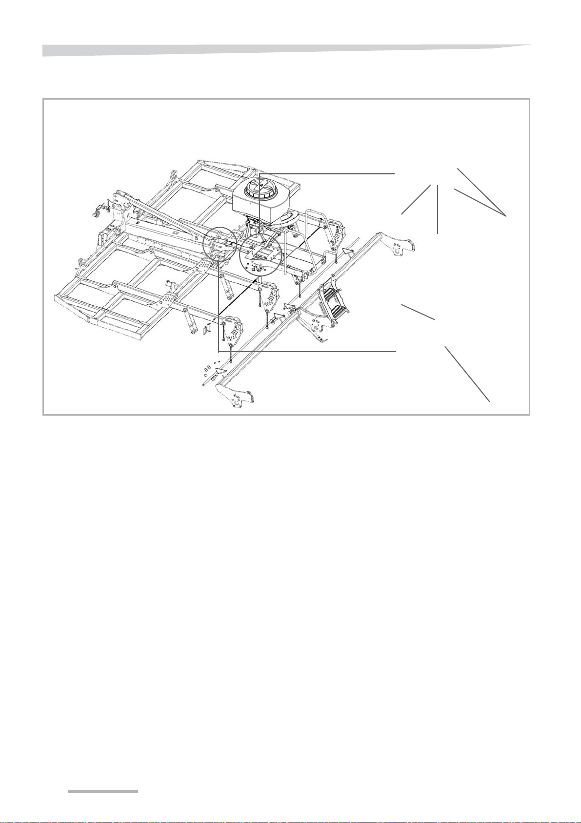
Delivery and assembly
Turn the hopper so that the hoses come out from the rear of the
machine.
Using U clamps, fix the support to the second beam of the main
frame.
Use the four long fixing screws.
Insert the 14 screws (B) in the tubes to fix the hopper.
Mounting diagrams for the
platform and hopper support
APlatform
B Hopper support
13

Delivery and assembly
CLC 2 rows 4m00 (13’1”)
570 mm
22
7/16”
545 mm
21
1/2”
CLC 3 rows 3m00 (9’10”)
CLC 3 rows 3m50 (11’6”)
480 mm
18
7/8”
600 mm
23
5/8”
CLC 3 rows 4m00 (13’1”)
14
Mounting the walkway
A
B
C
D
E
F
Procedure
Delivery and assembly
A Guardrail
B Reinforcement crossbar
C Upper part of stairs
D Lower part of stairs
E Fixing brackets
F Ball screw
Position the support arms for the walkway on the frame, respecting
the dimensions indicated on the diagrams page 13.
Install the walkway on the support arms using the fixing brackets
(E).
Using the same screws, fix the guardrail and reinforcement
crossbars.
Fix the upper part of the stairs to the extremity of the walkway.
Adjust the ball screws (F) to ensure the lower part of the stairs (D)
is maintained on the upper part (C).
15

Delivery and assembly
CLC Evo
CLC Pro
2 rows
3 rows
5 1/2”
5 1/2”
20”
13 9/16”
2 3/8”
21 7/16”
1 7/8”
10 3/8”
13 9/16”
5 9/16”
13 3/4”
18 7/8”
5
9/16”
5 9/16”
14
3/4”
22 7/16”
17 11/16” 23 5/8”
Mounting diagrams for
the platform
16
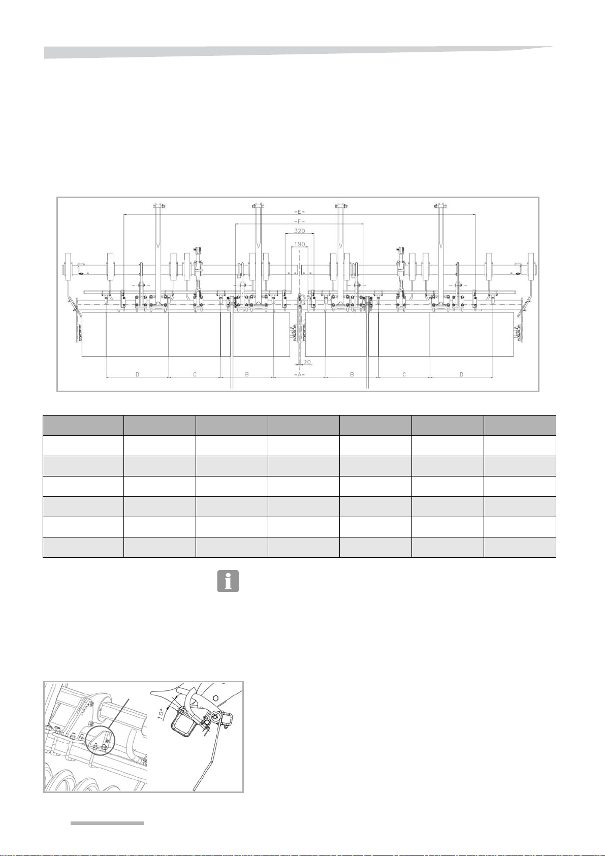
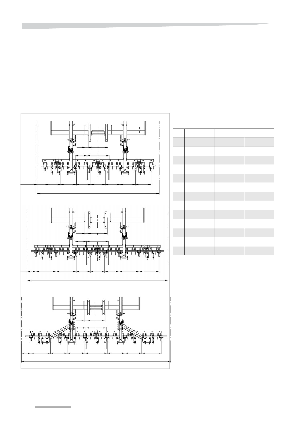
Positioning the
spreaders
Delivery and assembly
Task description
The spreaders must be distributed in a regular way on the machine,
although their position can be slightly offset depending on the
machines. The following table provides the mounting dimensions for
the different machines:
Machine A B C D E F
2R 3m00 arm
2R 3m00 //
2R 3m50 arm
2R 3m50 //
2R 4m00 arm
2R 4m00 //
3R 3m00 arm
3R 3m00 //
3R 3m50 arm
3R 3m50 //
3R 4m00 arm
3R 4m00 //
355 / 14” 355 / 14” 385 / 15 1/8” 385 / 15 1/8” 2257 / 89” 2605 / 103”
355 / 14” 355 / 14” 355 / 14” 355 / 14” 2257 / 89” 2605 / 103”
355 / 14” 355 / 14” 500 / 19 11/16” 500 / 19 11/16” 2757 / 109” 3065 / 121”
470 / 18 1/2” 430 / 16 15/16” 450 / 17 11/16” 450 / 17 11/16” 2757 / 109” 3130 / 123”
525 / 20 11/16” 525 / 20 11/16” 525 / 20 11/16” 425 / 16 11/16” 3057 / 120” 3500 / 138”
500 / 19 11/16” 475 / 18 11/16” 475 / 18 11/16” 550 / 21 5/8” 3057 / 120” 3500 / 138”
290 / 11 7/16” 290 / 11 7/16” 430 / 16 15/16” 430 / 16 15/16” 2257 / 89” 2590 / 102”
370 / 14 9/16” 370 / 14 9/16” 370 / 14 9/16” 370 / 14 9/16” 2257 / 89” 2590 / 102”
450 / 17 11/16” 455 / 17 15/16” 445 / 17 1/2” 440 / 17 5/16” 2757 / 109” 3130 / 123”
450 / 17 11/16” 455 / 17 15/16” 445 / 17 1/2” 440 / 17 5/16” 2757 / 109” 3130 / 123”
500 / 19 11/16” 500 / 19 11/16” 500 / 19 11/16” 500 / 19 11/16” 3057 / 120” 3500 / 138”
500 / 19 11/16” 500 / 19 11/16” 500 / 19 11/16” 500 / 19 11/16” 3057 / 120” 3500 / 138”
• “2R” corresponds to a machine with 2 rows of tines.
• “3R” corresponds to a machine with 3 rows of tines.
• "arm" corresponds to a machine whose rear tool is mounted on a
curved arm.
• “//” corresponds to a machine whose tool is mounted on a parallel-
ogram.
17

Delivery and assembly
Procedure
Levelling tines fixed to the roller beam:
Install the rail of spreaders in the lower position on the support.
18

Delivery and assembly
A
B
Adaptation on a machine equipped with levelling discs:
Fix the roller supports to the last 2 fixing holes of the parallelogram
(A).
Use and adapt the longest push bar (B) in order to keep the
working angle of the levelling discs.
Use the adapting kit for machines prior to June 2012, that do not
have a rear roller mounting position.
19
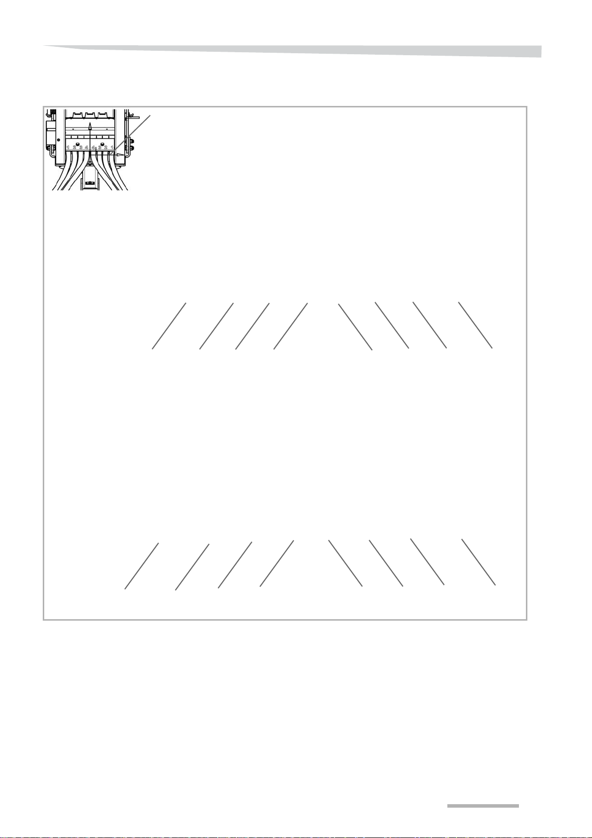
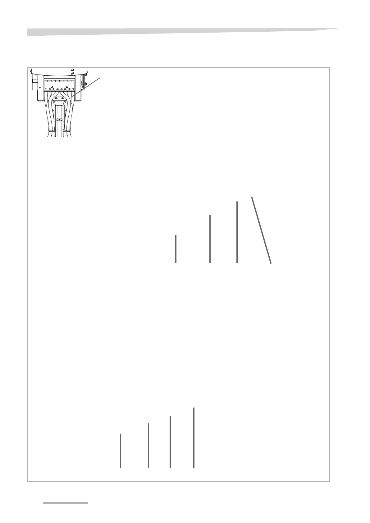
Delivery and assembly
Ensure that you respect the seed
outlet numbers compared to the spreader positions
Hose passage point
on the left side (the right side
is symmetrical).
Hose 1
Hose 2
Hose 3
Hose 4
Hose 1
Hose 2
Hose 3
Hose 4
A
Passage of hoses
Order of hose distribution for seed flow
Hose length (mm/in)
Left side / roller
Hopper N° 1 N° 2 N° 3 N° 4
CLC 2R 3m00 / 9’10” Offset 3335 /131” 3095 /122” 3075 /121” 2940 /116”
CLC 2R 3m50 / 11’6” Offset 3335 /131” 3095 /122” 3075 /121” 2940 /116”
CLC 2R 4m00 / 13’1” Offset 3550 /140” 3355 /132” 3645 /144” 3825 /151”
CLC 2R Wings 3m00 / 9’10” Centred 3195 /126” 2955 /116” 2935 /116” 2800 /110”
CLC 2R Wings 3m50 / 11’6” Centred 3195 /126” 2955 /116” 2935 /116” 2800 /110”
CLC 2R Wings 4m00 / 13’1” Centred 3410 /134” 3215 /127” 3505 /138” 3685 /145”
CLC 3R 3m00 / 9’10” Centred 3630 /143” 3260 /128” 3400 /134” 3120 /123”
CLC 3R 3m50 / 11’6” Centred 3630 /143” 3260 /128” 3400 /134” 3120 /123”
CLC 3R 4m00 / 13’1” Centred 3700 /146” 3605 /142” 3905 /154” 3975 /156”
20

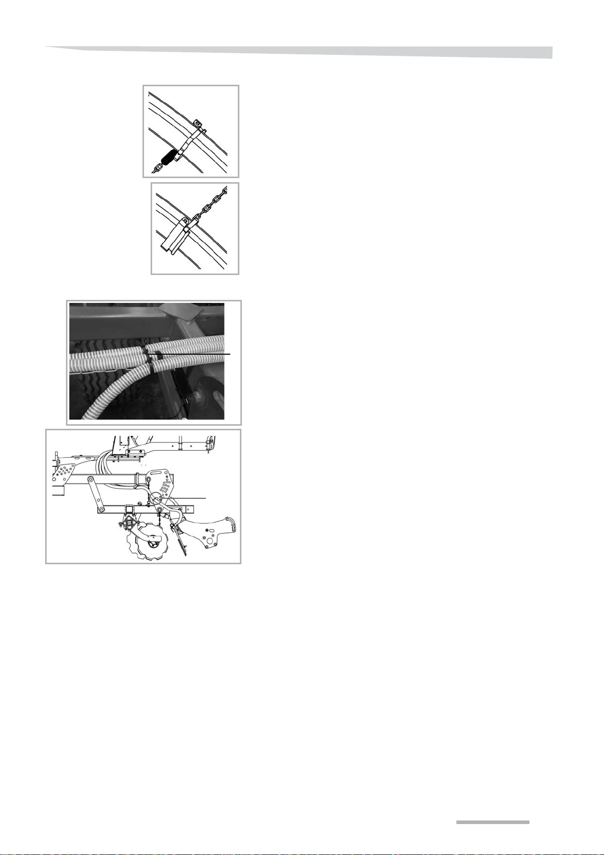
Delivery and assembly
Mounting on parallelogram
Mounting on curved arm
Hose supports have been designed to allow optimal passage of hoses
on the machine.
Fix the supports above the arms.
Group the hoses and pass them in the supports.
Cross the hoses when you connect them to the rail of spreaders.
The hoses that come out of the centre of the seed drill must supply
the exterior spreaders of the machine.
N
OTE
On 3 row cultivators, a hose guide (A) is installed on the stays.
21
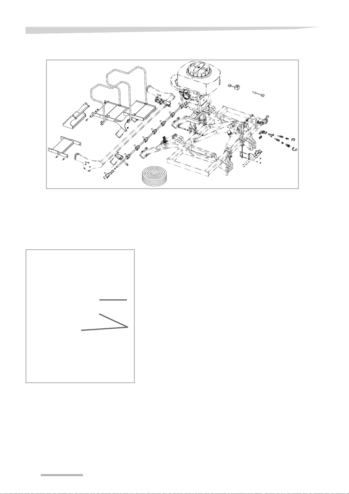
Delivery and assembly
A
B
C
D
E
Delivery and assembly
Folding CLC
Mounting the hopper support
Task description
Procedure
On folding cultivators, the hopper support and the access walkway are
fixed to the central frame using 4 screws.
Align the holes located at the rear extremity of the hopper support
(B) with the rear extremity of the central frame (A) of the machine.
Place the 4 hexagonal head M20x70 screws (C) in the holes.
Fix the screws using M20 nuts.
22

Mounting the hopper
Delivery and assembly
Task description
Procedure
Once the support is fixed to the machine, you now need to mount the
hopper onto it. The hopper is placed on the support and fixed using 14
screws.
Place the hopper on the support fixing plate, aligning the screw
holes.
Place the 12 screws M12x30 (D) on the sides and rear of the
hopper support.
Place the 2 screws M12x90 (E) in the holes located at the front of
the hopper support.
Fix the screws using M20 nuts.
23
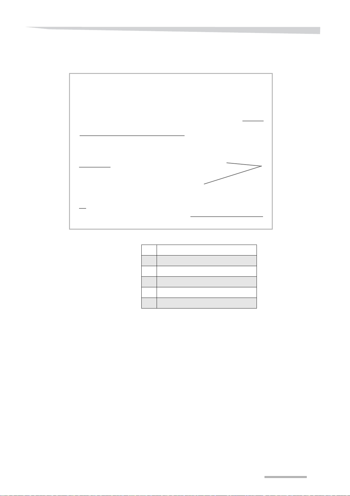
Delivery and assembly
A
Positioning the
spreaders
Task description
Machine A B C D E F
The spreaders must be distributed in a regular way on the machine,
although their position can be slightly offset depending on the
machines. The following table provides the mounting dimensions for
the different machines:
4m00 //
4m00 arm
4m50 //
4m50 arm
5m00 //
5m00 arm
Procedure
490 / 19 5/16” 530 / 20 7/8” 530 / 20 7/8” 530 / 20 7/8” 3920 / 154” 1430 / 56”
530 / 20 7/8” 530 / 20 7/8” 530 / 20 7/8” 530 / 20 7/8” 3920 / 154” 1300 / 51”
490 / 19 5/16” 590 / 23 1/4” 560 / 22” 560 / 22” 3520 / 139” 1430 / 56”
560 / 22” 560 / 22” 560 / 22” 560 / 22” 2520 / 99” 1300 / 51”
490 / 19 5/16 580 / 22 13/16” 570 / 22 7/16” 700 / 27 9/16” 2785 / 110” 1660 / 65”
585 / 23” 585 / 23” 580 / 22 13/16” 700 / 27 9/16” 2785 / 110” 1300 / 51”
• Column F corresponds to the distance between signalling
supports.
• "arm" corresponds to a machine whose rear tool is mounted on a
curved arm.
• “//” corresponds to a machine whose tool is mounted on a parallel-
ogram.
Levelling tines on CLC Pro Classic
Adjust the rail to the low position (A) to position the spreaders.
24
Delivery and assembly
Hose 1
Hose 1
Hose 2Hose 3Hose 4
Hose 2 Hose 3 Hose 4
Ensure that you respect the
seed outlet numbers compared to the
spreader positions.
CLC PRO
CLC PRO Classic
Hose 1 Hose 1Hose 2Hose 3Hose 4 Hose 2 Hose 3 Hose 4
Passage of hoses
Order of distribution for seed hoses on CLC Pro
25
Delivery and assembly
Ensure that you respect the
seed outlet numbers compared to the
spreader positions.
Hose 4 Hose 3 Hose 2 Hose 1
Hose 4 Hose 2 Hose 1
Hose 3
CLC Evo equipped with a parallelogram
CLC Evo equipped with a roller arm
Order of distribution for seeds on CLC Evo
26
Delivery and assembly
A
B
D
C
Use the support containing a spring (A).
Install the spring support on the exterior arm, ensuring that the
spring is directed towards the interior of the machine.
Fix the support using a metal clamping ring.
Use the link support (B).
Install the link support on the interior arm, ensuring that the link is
directed towards the exterior of the machine.
Fix the support using a metal clamping ring.
Attach the chain to the spring.
Tighten the chain so that the weight of the hoses does not make it
bend.
Attach the chain to the link.
Cut the excess chain.
Group the hoses and fix them to the chain using plastic rings.
Fix the hoses to the extremity of the machine using a washer (D).
Check in the upper and lower positions that there are no blocking
or crushing points for the hoses.
27
Delivery and assembly
A
B
Delivery and assembly
Rigid Qualidisc
Mounting the hopper
support and the hopper
Procedure
Turn the hopper so that the hoses come out from the rear of the
machine.
Using U clamps (A), fix the support to the second beam of the main
frame.
Insert the two screws M20x160.
Tighten the M20x160 screws to 500Nm torque.
Insert the 12 screws M12x35 (B) in the angles of the hopper
support.
Place the bolts.
28
Mounting the
A
C
D
E
B
F
walkway
Delivery and assembly
Procedure
APlatform
B Retractable step
C Walkway extension
D Guardrail
EBrackets
F Roller beam
Centre the support for the walkway on the roller beam (F).
Position the two brackets (E) on the roller beam.
Bolt the brackets.
Machines equipped with double rollers:
Attach the walkway extension (C) between the platform (A) and the
retractable step (B).
29
Delivery and assembly
3m00 / 9’10”
3m50 / 11’6”
4m00 / 13’1”
A
B
C
D
E
FG
H
I
J
KL
M
A
B
C
D
A
B
C
D
E
F
G
HI
J
KL
M
E
F
G
H
I
J
KL
M
Positioning the
spreaders
Task description
Different accessories such as a comb harrow or rollers can be
mounted on disc cultivators. The tool has no effect on the mounting of
the spreader rail.
The spreaders must be distributed in a regular way on the machine,
although their position can be slightly offset depending on the
machines. The following tables specify the mounting dimensions (mm/
in) for the different machines:
3m00 (9’10”) 3m50 (11’6”) 4m00 (13’1”)
A 73 / 2 7/8” 73 / 2 7/8” 73 / 2 7/8”
B 484 / 19” 484 / 19” 484 / 19”
C 286 / 11 1/4” 286 / 11 1/4” 286 / 11 1/4”
D 548 / 21
E 197.5 / 7 3/4” 217.5 /8 9/16” 250 / 9 7/8”
F 385 / 14” 500/ 19
G 385 / 14” 500/ 19 11/16” 450 / 17 3/4”
H 355 / 15
I 355 / 15 3/16” 355 / 15 3/16” 600 / 23 5/8”
9/16” 548 / 21 9/16” 548 / 21 9/16”
11/16” 525/ 20 11/16”
3/16” 355 / 15 3/16” 475/ 18 11/16”
J 355 / 15
K 385 / 14” 500/ 19 11/16” 450 / 17 3/4”
L 385 / 14” 500/ 19
M 3000 / 118” 3500 / 138” 4000 / 157”
3/16” 355 / 15 3/16” 475/ 18 11/16”
11/16” 525/ 20 11/16”
30
 Loading...