

Kvaser USBcan R User's
Guide
Copyright 2001-2011 Kvaser AB, Mölndal, Sweden
http://www.kvaser.com
Last updated Thursday, 28 April 2011
We believe that the information contained herein was accurate in all respects at the time of printing. Kvaser AB cannot, however, assume
any responsibility for errors or omissions in this text. Also note that the information in this document is subject to change without notice and
should not be construed as a commitment by Kvaser AB.

Kvaser USBcan R User's Guide 2(17)
Kvaser AB, Mölndal, Sweden — www.kvaser.com
(This page is intentionally left blank.)

Kvaser USBcan R User's Guide 3(17)
Kvaser AB, Mölndal, Sweden — www.kvaser.com
1 Table of Contents
Kvaser USBcan R User's Guide ..............................................................................................1
1 Table of Contents ..............................................................................................................3
2 About this manual .............................................................................................................4
3 Introduction ........................................................................................................................5
3.1 Welcome to Kvaser USBcan R ....................................................................................5
3.2 Major features of Kvaser USBcan R ............................................................................5
3.3 Additional software and documentation .......................................................................6
4 Kvaser USBcan R hardware .............................................................................................7
4.1 Hardware installation ....................................................................................................7
4.2 USB connector .............................................................................................................7
4.3 CAN channels ..............................................................................................................7
4.4 LED indicators ..............................................................................................................8
5 How to use the Kvaser USBcan R ...................................................................................9
5.1 Troubleshooting ...........................................................................................................9
6 Appendices ..................................................................................................................... 10
6.1 System requirements ................................................................................................ 10
6.2 Technical data ........................................................................................................... 10
6.3 CAN connectors ........................................................................................................ 11
6.4 Required driver version ............................................................................................. 13
6.5 CAN bus termination ................................................................................................. 13
7 Frequently Asked Questions ......................................................................................... 14
8 Legal acknowledgements .............................................................................................. 15
8.1 Usage warning .......................................................................................................... 15
8.2 EMC compliance statement ...................................................................................... 16
8.3 WEEE compliance statement.................................................................................... 16
8.4 RoHS compliance statement..................................................................................... 16
8.5 Patents, copyrights and trademarks ......................................................................... 16
9 Document revision history ............................................................................................ 17

Kvaser USBcan R User's Guide 4(17)
Kvaser AB, Mölndal, Sweden — www.kvaser.com
2 About this manual
This manual is intended for Kvaser USBcan R users. This manual contains a description of
the hardware’s properties and general instructions for connecting the device to a computer.

Kvaser USBcan R User's Guide 5(17)
Kvaser AB, Mölndal, Sweden — www.kvaser.com
3 Introduction
This section will describe the functions and features of the Kvaser USBcan R.
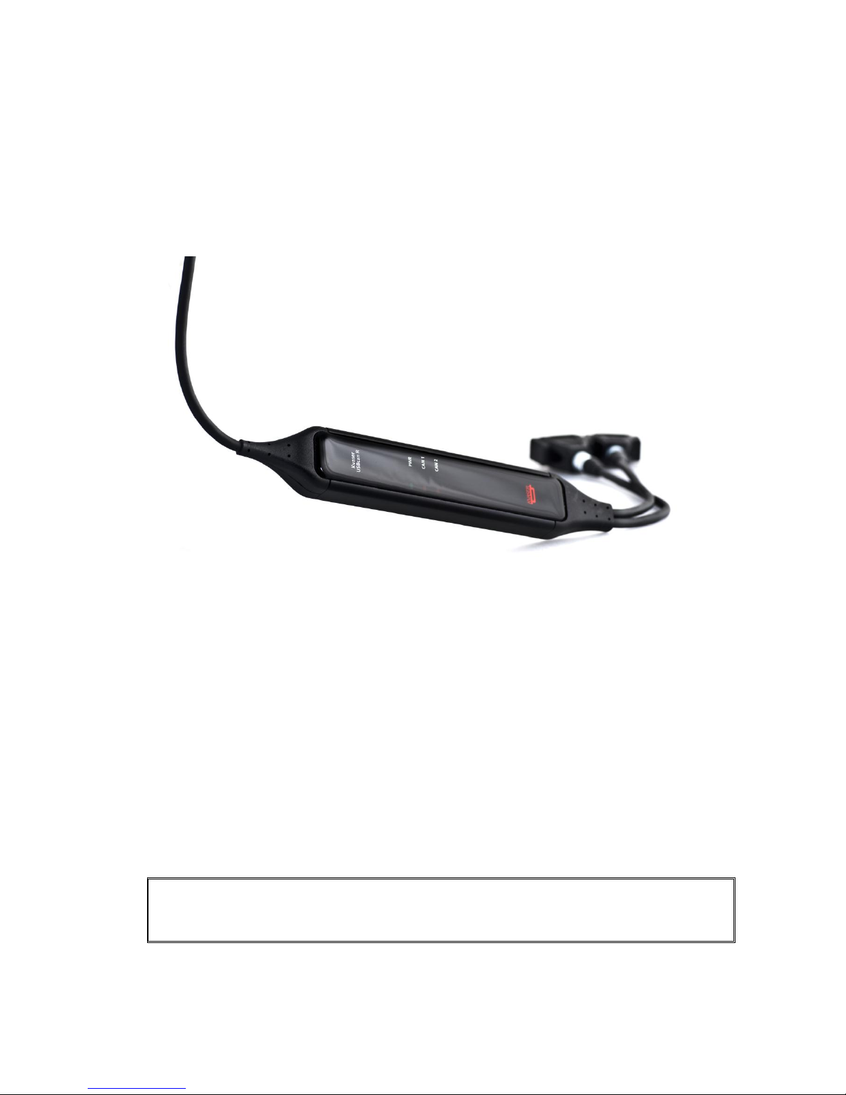
3.1 Welcome to Kvaser USBcan R
Figure 1. Kvaser USBcan R.
The Kvaser USBcan R is a powerful two channel, real time, CAN to USB interface.
With quick reaction times and high data throughput, the Kvaser USBcan R is perfect for rapid
ECU programming, advanced bus analyzers, and efficient development work.
3.2 Major features of Kvaser USBcan R
Quick and easy plug-and-play installation.
Supports both 11-bit (CAN 2.0A) and 29-bit (CAN 2.0B active) identifiers.
CAN messages are time-stamped with 100 microsecond accuracy.
Supports data and remote frames.
Detects error frames.
Large on-board RAM buffer for CAN messages.
Handles up to 8000 messages per second.
100% compatible with applications written with Kvaser CANLIB for Kvaser hardware
such as LAPcan, PCIcan, and USBcan.
Two high-speed CAN connections (compliant with ISO 11898-2), 5 kbit/s up to 1
Mbit/s.
Fully compatible with all higher layer protocols including J1939, CANopen, NMEA
2000® and DeviceNet.
One USB 2.0 HiSpeed connection with data rates up to 480 Mbit/s. The device can
also be used in USB 1.1 slots (with data rates up to 12 Mbit/s).
IP67 rated lightweight aluminum housing with dimensions 160 x 20 x 30 mm (6.3 x
0.8 x 1.2 inch) – easy to tuck away (e.g. in a vehicle during a test drive).
Simultaneous operation of multiple devices.
Polyurethane cabling for extreme environments.
Low power-consumption.

Kvaser USBcan R User's Guide 6(17)
Kvaser AB, Mölndal, Sweden — www.kvaser.com
3.3 Additional software and documentation
Kvaser CANLIB SDK, which includes everything you need to develop software for
Kvaser CAN hardware. The SDK includes full documentation and many sample
programs, written in C, C++, C#, Delphi, and Visual Basic. All Kvaser CAN interface
hardware shares a common software API. Programs written for one board type will
run without modifications on the other board types!
On-line documentation in Windows® HTML Help and Adobe Acrobat format.

Kvaser USBcan R User's Guide 7(17)
Kvaser AB, Mölndal, Sweden — www.kvaser.com
4 Kvaser USBcan R hardware
In this section you can read more about the CAN bus channels, USB connector, and LED
indicators.
4.1 Hardware installation
The Kvaser USBcan R may be inserted in any unused USB socket on the host computer.
You do not need to switch the power off before inserting or removing the device. For the
Kvaser USBcan R to communicate with the host computer, the correct version of the Kvaser
driver and firmware must be installed. The firmware is downloaded and installed directly on
the Kvaser USBcan R and the driver is installed on the host computer.
The delivery package of Kvaser USBcan R contains:
Kvaser USBcan R
4.2 USB connector
The Kvaser USBcan R has a standard USB type ―A‖ plug. If you need a longer cable, you
can use USB hubs or USB extension cables with a built-in hub. By chaining up to 5 hubs, you
can achieve a cable length of up to 25 meters (approx. 83 ft.).
4.3 CAN channels
The standard Kvaser USBcan R has two independent CAN channels with a common ground.
The connectors for these channels are shown in Figure 2.
CAN channel
connectors
USB device
connector
Figure 2: Connections on the Kvaser USBcan R. The two CAN channels are to the left
and the USB device connector is to the right.
Kvaser USBcan R User's Guide 8(17)
Kvaser AB, Mölndal, Sweden — www.kvaser.com
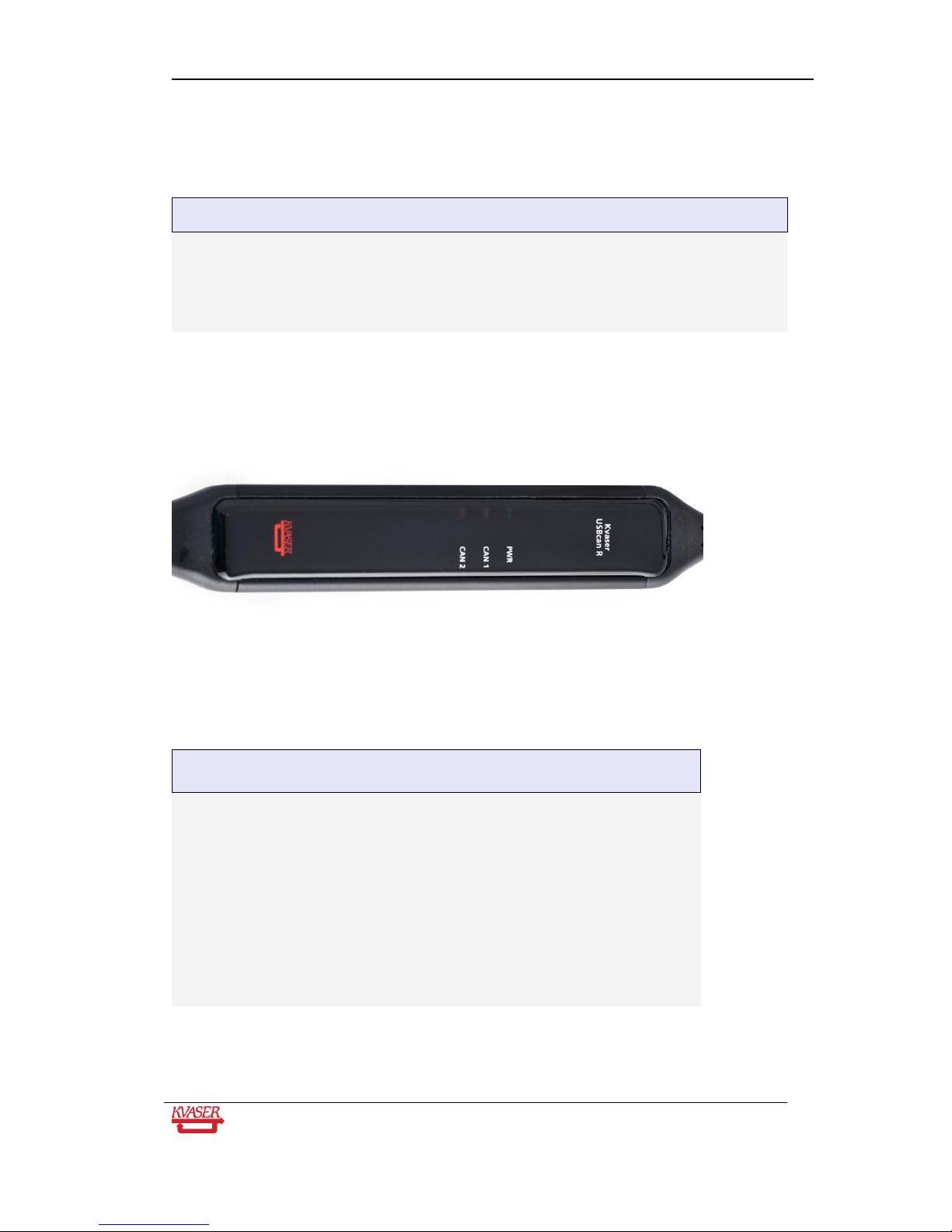
4.4 LED indicators
Table 1: LED indicators overview.
LED
General meaning
PWR (Green)
Power and general status.
CAN 1 (Yellow)
Status for CAN channel 1.
CAN 2 (Yellow)
Status for CAN channel 2.
Figure 3. LEDs on the Kvaser USBcan R.
Table 2: LED indicators, detailed meaning.
PWR
(Green)
CAN 1
(Yellow)
CAN 2
(Yellow)
Meaning
Slow flash
Waiting for USB connection with the PC.
Steady
Power ON (The device is connected to
the computer).
Short flash
CAN traffic on channel 1.
Short flash
CAN traffic on channel 2.
Fast flash
Firmware configuration error (should not
normally happen, so please contact
support).
Kvaser USBcan R User's Guide 9(17)
Kvaser AB, Mölndal, Sweden — www.kvaser.com
5 How to use the Kvaser USBcan R
To use the Kvaser USBcan R as a CAN interface; connect the unit to a free USB socket on
your PC or USB hub.
When used as a CAN interface, the green LED will be illuminated, and the yellow
LEDs will emit short flashes when CAN messages are transmitted and received.
5.1 Troubleshooting
Use ―Kvaser Hardware‖ in the Control Panel to verify that the computer really
can talk to the Kvaser USBcan R. Read out the firmware version. If the
firmware version is all zeroes, there are communication problems.
If the LEDs are flashing or glowing, compare the pattern with the specified LED
indicators in Table 1 and Table 2.
If the LEDs are not flashing or glowing at all, check the power supplied through
the USB connection.

Kvaser USBcan R User's Guide 10(17)
Kvaser AB, Mölndal, Sweden — www.kvaser.com
6 Appendices
In this section you will find technical information about the Kvaser USBcan R and its
connectors.
6.1 System requirements
A USB interface. Use USB 2.0 HiSpeed for optimum results, although the device will
also work with a USB 1.1 interface.
6.2 Technical data
In Table 3 below you will find the Kvaser USBcan R’s technical specifications.
Table 3: Kvaser USBcan R Technical specifications.
CAN Channels
2 (CAN 2.0A and 2.0B active).
CAN Transceivers
Compliant with ISO 11898-2
CAN Controller
Built into the M32C
Microcontroller
Renesas M32C
CAN Bit Rate
5 kbit/s to 1 Mbit/s
Timestamp resolution
100 µs
Error Frame Detection
Yes, both channels.
Error Frame Generation
No.
PC interface
USB 2.0. Supports HiSpeed (HS) at 480 Mbit/s. Compatible with USB
1.1 Full Speed (FS) at 12 Mbit/s.
Power consumption
~ 5V and 130mA powered from the USB.
Software requirements
Windows XP or later. (For other operating systems, see Kvaser web or
contact Kvaser support.)
Hardware configuration
Done by software (Plug & Play).
Dimensions (W x L x H)
30 x 160 x 20 mm (1.2 x 6.3 x 0.8 inch)
Operating temperature
-40 ºC ... +85 ºC
Weight
Approx 160 g

Kvaser USBcan R User's Guide 11(17)
Kvaser AB, Mölndal, Sweden — www.kvaser.com
Storage temperature
-40 ºC ... +85 ºC
Relative Humidity
0% ... 95% (non-condensing.)
6.3 CAN connectors
The Kvaser USBcan R has two high-speed CAN channels. Both CAN channels have 9-pin DSUB connectors (see Figure 4) with the pinning described below (see Table 4 and
Table 5).
Figure 4: The D-SUB connector pin numbers on a CAN channel.
Table 4: D-SUB pin configuration of the CAN channel 1.
The CAN channel 1 has the following pin configuration.
(Auto-reset fuses protect Pins 2, 3, 4, 7 and 9.)
D-SUB pin number
Function
1 Not connected.
2 CAN_L
3 GND
4 Reserved; do not connect
5 Shield
6 Not connected.
7 CAN_H
8 Not connected.
9 Not connected.

Kvaser USBcan R User's Guide 12(17)
Kvaser AB, Mölndal, Sweden — www.kvaser.com
Table 5: D-SUB pin configuration of the CAN channel 2.
The CAN 2 channel has the following pin configuration.
(Auto-reset fuses protect Pins 2, 3, 4, 7 and 9.)
D-SUB pin number
Function
1 Not connected.
2 CAN_L
3 GND
4 Reserved; do not connect
5 Shield
6 Not connected.
7 CAN_H
8 Not connected.
9 Not connected.
Note: Always connect the ground pin on the D-SUB to the ground of your CAN
bus.

Kvaser USBcan R User's Guide 13(17)
Kvaser AB, Mölndal, Sweden — www.kvaser.com
6.4 Required driver version
You need at least version (CANLIB) 4.3 of the driver to use your Kvaser USBcan R.
6.5 CAN bus termination
Every CAN bus must be terminated with a 120 Ohm resistor at each end of the bus. The
Kvaser USBcan R does not contain any CAN bus terminators, because their inclusion could
cause severe disturbance in a system which is already correctly terminated.
For laboratory or testing use, the exact value of the termination resistors is not always critical.
Sometimes a single terminator is sufficient. For production, proper termination is essential. If
you see error frames on the bus, you should check the termination.
To save yourself a lot of trouble, always terminate the CAN bus properly.

Kvaser USBcan R User's Guide 14(17)
Kvaser AB, Mölndal, Sweden — www.kvaser.com
7 Frequently Asked Questions
Q: Could I use several Kvaser USBcan R?
A: Yes, no problem.
Q: If I reboot my computer, will the Kvaser USBcan R and other products have the
same channel numbers as before?
A: Yes, they will try to reuse the old channel numbers.
Q: How can I identify which Kvaser USBcan R has a certain channel number?
A: Use ―Kvaser Hardware‖ to flash the LEDs on the Kvaser USBcan R.

Kvaser USBcan R User's Guide 15(17)
Kvaser AB, Mölndal, Sweden — www.kvaser.com
8 Legal acknowledgements
8.1 Usage warning
WARNING FOR ALL USERS
WARNING! - YOUR USE OF THIS DEVICE MUST BE DONE WITH CAUTION
AND A FULL UNDERSTANDING OF THE RISKS!
THIS WARNING IS PRESENTED TO INFORM YOU THAT THE OPERATION OF
THIS DEVICE MAY BE DANGEROUS. YOUR ACTIONS CAN INFLUENCE THE
BEHAVIOR OF A CAN-BASED DISTRIBUTED EMBEDDED SYSTEM, AND
DEPENDING ON THE APPLICATION, THE CONSEQUENCES OF YOUR
IMPROPER ACTIONS COULD CAUSE SERIOUS OPERATIONAL
MALFUNCTION, LOSS OF INFORMATION, DAMAGE TO EQUIPMENT, AND
PHYSICAL INJURY TO YOURSELF AND OTHERS. A POTENTIALLY
HAZARDOUS OPERATING CONDITION IS PRESENT WHEN THE FOLLOWING
TWO CONDITIONS ARE CONCURRENTLY TRUE: THE PRODUCT IS
PHYSICALLY INTERCONNECTED TO A REAL DISTRIBUTED EMBEDDED
SYSTEM; AND THE FUNCTIONS AND OPERATIONS OF THE REAL
DISTRIBUTED EMBEDDED SYSTEM ARE CONTROLLABLE OR INFLUENCED
BY THE USE OF THE CAN NETWORK. A POTENTIALLY HAZARDOUS
OPERATING CONDITION MAY RESULT FROM THE ACTIVITY OR NONACTIVITY OF SOME DISTRIBUTED EMBEDDED SYSTEM FUNCTIONS AND
OPERATIONS, WHICH MAY RESULT IN SERIOUS PHYSICAL HARM OR
DEATH OR CAUSE DAMAGE TO EQUIPMENT, DEVICES, OR THE
SURROUNDING ENVIRONMENT.
WITH THIS DEVICE, YOU MAY POTENTIALLY:
CAUSE A CHANGE IN THE OPERATION OF THE SYSTEM, MODULE,
DEVICE, CIRCUIT, OR OUTPUT.
TURN ON OR ACTIVATE A MODULE, DEVICE, CIRCUIT, OUTPUT, OR
FUNCTION.
TURN OFF OR DEACTIVATE A MODULE, DEVICE, CIRCUIT, OUTPUT,
OR FUNCTION.
INHIBIT, TURN OFF, OR DEACTIVATE NORMAL OPERATION.
MODIFY THE BEHAVIOR OF A DISTRIBUTED PRODUCT.
ACTIVATE AN UNINTENDED OPERATION.
PLACE THE SYSTEM, MODULE, DEVICE, CIRCUIT, OR OUTPUT INTO
AN UNINTENDED MODE.
ONLY THOSE PERSONS WHO:
(A) ARE PROPERLY TRAINED AND QUALIFIED WITH RESPECT TO THE USE
OF THE DEVICE,
(B) UNDERSTAND THE WARNINGS ABOVE, AND
(C) UNDERSTAND HOW THIS DEVICE INTERACTS WITH AND IMPACTS THE
FUNCTION AND SAFETY OF OTHER PRODUCTS IN A DISTRIBUTED SYSTEM
AND THE APPLICATION FOR WHICH THIS DEVICE WILL BE APPLIED, MAY
USE THE DEVICE.
PLEASE NOTE THAT YOU CAN INTEGRATE THIS PRODUCT AS A
SUBSYSTEM INTO HIGHER-LEVEL SYSTEMS. IN CASE YOU DO SO, KVASER

Kvaser USBcan R User's Guide 16(17)
Kvaser AB, Mölndal, Sweden — www.kvaser.com
AB HEREBY DECLARES THAT KVASER AB'S WARRANTY SHALL BE LIMITED
TO THE CORRECTION OF DEFECTS, AND KVASER AB HEREBY EXPRESSLY
DISCLAIMS ANY LIABILITY OVER AND ABOVE THE REFUNDING OF THE
PRICE PAID FOR THIS DEVICE, SINCE KVASER AB DOES NOT HAVE ANY
INFLUENCE ON THE IMPLEMENTATIONS OF THE HIGHER-LEVER SYSTEM,
WHICH MAY BE DEFECTIVE.
8.2 EMC compliance statement
CE regulation:
This product is in accordance with the directive 2004/108/EC regulating the electromagnetic
compatibility.
FCC regulation:
This product has been tested and found to comply with the limits for a Class B digital device,
pursuant to Part 15 of the FCC Rules. These limits are designed to provide reasonable
protection against harmful interference in a residential installation. This equipment generates,
uses and can radiate radio frequency energy and, if not installed and used in accordance with
the instructions, may cause harmful interference to radio communications. However, there is
no guarantee that interference will not occur in a particular installation. If this equipment does
cause harmful interference to radio or television reception, which can be determined by
turning the equipment off and on, the user is encouraged to try to correct the interference by
one or more of the following measures:
Reorient or relocate the receiving antenna
Increase the separation between the equipment and receiver
Connect the equipment into an outlet on a circuit different from that to which the
receiver is connected
Consult the dealer or an experienced radio/TV technician for help
8.3 WEEE compliance statement
This product is sold in compliance with the directive 2002/96/EC of the European
Parliament on Waste Electrical and Electronic Equipment (WEEE.)
8.4 RoHS compliance statement
This product is manufactured in accordance with directive 2002/95/EC on the Restriction of
the use of certain Hazardous Substances in electrical and electronic equipment (RoHS).
8.5 Patents, copyrights and trademarks
All trademarks are the property of their respective owner.
Windows® is a registered trademark of Microsoft Corporation in the United States and other
countries.
MagiSync is a trademark of Kvaser AB.
DeviceNet is a Trademark of Open DeviceNet Vendor Association, Inc.
NMEA 2000® is the registered trademark of the National Marine Electronics Association, Inc.

Kvaser USBcan R User's Guide 17(17)
Kvaser AB, Mölndal, Sweden — www.kvaser.com
9 Document revision history
Revision
Date
Changes
1
2010-11-22
Original revision
1.2
2010-12-12
Updated regulation text, Operating and storage temperature
1.3
2011-01-14
Updated supported OS list
 Loading...