

Kvarta RDS300, RDS500, RDS1000 User Manual
www.kvarta.net 1/36
1
RDS300/RDS500/RDS1000 User Manual 3.10
RDS300/RDS500/RDS1000
DYNAMIC RDS ENCODERS KVARTA
USER’S MANUAL

www.kvarta.net 2/36
2
RDS300/RDS500/RDS1000 User Manual 3.10
Contents
1. INTRODUCTION ............................................................................................................................... 4
1.1. About KVARTA Ltd. .................................................................................................................. 4
1.2. About RDS and RBDS ............................................................................................................... 4
1.3. Functions of RDS/RBDS. .......................................................................................................... 5
1.4. WHAT ABOUT U.S.? ................................................................................................................. 7
1.5. A FEW WORDS ABOUT PS AND RT .......................................................................................... 7
2. Dynamic RDS Encoder Kvarta .......................................................................................................... 8
2.1. INCLUDED ACCESSORIES ......................................................................................................... 8
2.2. GENERAL SPECIFICATIONS OF THE RDS ENCODER .................................................................. 9
3. GETTING CONNECTED ....................................................................................................................... 10
3.1. CONFIGURING ‘LOOP THROUGH’ OR ‘SIDE CHAIN’ MODE ........................................................ 10
3.2. PHYSICAL INSTALLATION ............................................................................................................ 10
3.3. CONNECTION TO THE BROADCAST CHAIN ................................................................................. 11
3.4. SYNCHONIZING THE RDS SUBCARRIER ....................................................................................... 11
3.5. SETTING THE RDS LEVEL ............................................................................................................. 12
3.6. LED Indication ............................................................................................................................. 12
4. CONFIGURATION AND OPERATION ............................................................................................... 13
4.1. COMMUNICATING THROUGH THE CONSOLE AND COM PORTS ........................................... 13
4.2. COMMUNICATING VIA TCP/IP ............................................................................................... 14
5. ADVANCED FUNCTIONS................................................................................................................. 15
5.1. BROADCASTING TRAFFIC DATA (TMC)* ................................................................................ 15
5.2. BROADCASTING OPEN DATA APPLICATIONS (ODA)* ............................................................ 15
5.3. PAGING APPLICATIONS*........................................................................................................ 16
5.4. BROADCASTING ACCURATE TIME ......................................................................................... 17
6. USING THE UECP PROTOCOL ............................................................................................................. 18
6.1. ABOUT UECP ............................................................................................................................... 18
6.2. UECP AND THE RDS1000 ............................................................................................................ 18
6.3. UECP COMMANDS AND FUNCTIONS* ....................................................................................... 19
7. RDS GLOSSARY ................................................................................................................................... 20
APPENDIX A – PTY, PTYN ....................................................................................................................... 23
APPENDIX B – HOW TO SET UP THE RDS1000 FOR PS NAME OR RADIO TEXT SCROLLING ................. 24
A. UECP configuration. (Expert only) ................................................................................................. 25
B. ASCII configuration. ....................................................................................................................... 26

www.kvarta.net 3/36
3
RDS300/RDS500/RDS1000 User Manual 3.10
APPENDIX C - RDS300/RDS500/RDS1000 ASCII COMMAND SET ......................................................... 29
C.1. HELP COMMANDS ................................................................................................................. 29
C.2. RDS SYSTEM COMMANDS ..................................................................................................... 29
C.3. DSN AND PSN CONFIGURATION ............................................................................................ 30
C.4. Dynamic PS COMMANDS ...................................................................................................... 31
C.5. EON COMMANDS* ................................................................................................................ 32
C.6. ODA COMMANDS* ................................................................................................................ 32
C.7. CLOCK COMMANDS ............................................................................................................... 32
C.8. PAGING COMMANDS* .......................................................................................................... 33
C.9. SCHEDULER COMMANDS* .................................................................................................... 33
C.10. NETWORK COMMANDS .................................................................................................... 34
C.11. COMMUNICATION COMMANDS ....................................................................................... 34
C.12. RT+ COMMANDS* ............................................................................................................. 35
C.13. MONITORING COMMANDS* ............................................................................................. 35
C.14. SNMP COMMANDS* ......................................................................................................... 36
C.15. SPECIAL COMMANDS ........................................................................................................ 36
* Depends on the model RDS300/RDS500/RDS1000

www.kvarta.net 4/36
4
RDS300/RDS500/RDS1000 User Manual 3.10
1. INTRODUCTION
1.1. About KVARTA Ltd.
For more than 20 years, Kvarta has been developing products for Broadcasters and CATV providers.
Our solutions are used by major radio and television broadcasters and regulatory agencies.
Broadcast is our passion. We understand your challenges and have designed many solutions perfectly
adapted to your needs. These include RDS encoders, FM Radio monitors and CATV systems.
KVARTA has a reputation for excellence and innovation among its clients and partners.
1.2. About RDS and RBDS
RDS, or Radio Data System, was developed in Europe in the mid 1980s. It is a method of broadcasting
a low rate data stream on an FM stations’ 57 KHz subcarrier. In many countries around the world,
RDS can actually control the receiver in a car, switching it from frequency to frequency as the vehicle
travels; much like a cellular phone switches from tower to tower. In this mode, a traveler can journey
from one end of a country to another while listening to the same radio program, even though his
radio may seamlessly tune dozens of separate frequencies along the way. RDS can even cause a
receiver to interrupt a CD that is playing to tune in a traffic report, if that is what the listener desires.
The current standards of European RDS broadcasting are reflected in the CENELEC standard EN
50067, which is available on line for research and review, at http://www.rds.org.uk
The KVARTA RDS1000 conforms to all standards and specifications of EN 50067.
RBDS, or Radio Broadcast Data System, is the American standard of RDS data broadcasting, first
introduced into the US in 1993. A significant upgrade of the standards came about in 1998, leaving us
with the standards we have as of this writing (2009). These standards, collectively known as NRSC-4,
are available on line at http://www.nrscstandards.org
.
The data rate for RBDS is small, by today’s broadband and T1 standards. The overall data rate is less
than 1,200 bits per second. A significant number of those bits are used for error correction, so the
usable data rate is a mere 730 bits per second. The data is transmitted in 32 separate ‘groups’, which
are labeled 0A, 0B, 1A, etc. up to group 15B. The purpose of each separate group of data is rigidly
defined, to allow the receivers to know where to ‘look’ for a particular piece of data, and to allow the
most flexibility and possibility of future expansion. Here is a short description of the use of each of
the thirty two groups. If you didn’t already know, ODA stands for Open Data :
www.kvarta.net 5/36
5
RDS300/RDS500/RDS1000 User Manual 3.10
Group
Description
Group
Description
0A
Basic tuning and switching information
8A
Traffic Message Channel or ODA
0B
Basic tuning and switching information
8B
Open Data Applications
1A
Program Item Number and slow labeling
codes
9A
Emergency Warning System or ODA
1B
Program Item Number
9B
Open Data Applications
2A
Radiotext only
10A
Program Type Name
2B
Radiotext only
10B
Open Data Applications
3A
Applications Identification for ODA
11A
Open Data Applications
3B
Open Data Applications
11B
Open Data Applications
4A
Clock-time and date
12A
Open Data Applications
4B
Open Data Applications
12B
Open Data Applications
5A
Transparent Data Channels or ODA
13A
Enhanced Radio Paging or ODA
5B
Transparent Data Channels or ODA
13B
Open Data Applications
6A
In House applications or ODA
14A
Enhanced Other Networks information only
6B
In House applications or ODA
14B
Enhanced Other Networks information only
7A
Radio Paging or ODA
15A
Undefined
7B
Open Data Applications
15B
Fast switching information only
The KVARTA RDS/RBDS RDS1000 encoder is designed to be fully compatible with both the European
and American standards, and broadcast of any or all of the data groups is fully user selectable, to
allow the broadcaster to tailor the RBDS data stream to fit their needs.
1.3. Functions of RDS/RBDS.
RDS is a powerful tool for communicating within a network of transmitters, and controlling and
programming the receivers tuned to that network. Although the functions of RDS are almost too
numerous to detail, these are the primary types of data transmitted over RDS/RBS.
1. The PI, or Program Identification, code. This is a hexadecimal code that identifies a
particular program. This is a required item, as the PI code acts as the digital identification for
your station. In Europe and other countries, the PI code is assigned by the authorities; in the US it
can be calculated by using your stations’ call letters, provided you have a four-letter set. See the
PI section of Appendix A for the calculation, For three letter calls, the PIs have been assigned a
separate set of hex codes that are listed in the RBDS Standard (NRSC-4), also available on line.
The PI code is transmitted in each of the 32 possible groups of RBDS data.
2. The PTY, or Program Type, code. This is a numerical code that labels your format, the type of
programming carried on your station. Be it Top 40, Rock, Classical, Religious or Talk, there is a
code for you (or at least something close). The transmission of this code will allow the listener to
search the FM band for a particular format, instead of by frequency. The codes have been
defined and are listed in the ‘PTY’ section of Appendix A. BEWARE - the PTY codes for the
European (CENELEC) standard are different from those defined by the United States standard
(NRSC), so be certain you’re looking at the right part of the table to broadcast the correct code.
3. The PTYN, or Program Type Name. Just 8 characters.

www.kvarta.net 6/36
6
RDS300/RDS500/RDS1000 User Manual 3.10
4. The M/S flag. A simple ‘yes’ or ‘no’ type flag to indicate whether a stations’ programming is
primarily Music or Speech.
5. The TP, or Traffic Program, flag. This is an indication of whether your station carries traffic
information on a regular basis.
6. The TA, or Traffic Announcement, flag. This is a more critical indicator that says to the
receiver “We are broadcasting a traffic report right now!” WARNING! There are strict
regulations on the use of this flag! If a receiver is set to respond to this flag, it can actually force
the tuner to a new station or interrupt a CD or cassette to hear the traffic information! It is illegal
to have this flag set to ‘on’ if your station is not currently broadcasting traffic information!
7. Clock Time. Allows a receiver to display a time generated by a KVARTA encoder. For more on
the use of this feature, see the ‘Broadcasting Accurate Time’ section under ‘Advanced Functions’.
8. ODA, or Open Data Applications. Just what it says, use of part of the RDS/RBDS data stream
to send any type of data you like, for whatever purpose you desire. Many stations are finding this
application has the potential to generate additional revenue.
NOTE: Use of ODA applications requires obtaining an Application Identification Code (AID). This code
will be broadcast in the 3A groups and identifies the type of application used to transmit data in the
ODA groups.
9. PS, or Program Service, code. This (along with Radio text) is the part of the RDS data that
actually displays alphanumeric information on the listeners’ radio.
10. RT, or Radio Text, code. Another alphanumeric type display. Maximum 64 characters.
11. PIN, Program Identification Number.
The transmitted Programme Item Number code will be the scheduled broadcast start time and
day of month as published by the broadcaster.
12. DI, Decoder Identification. Rarely used, but tells the receiver to decode the broadcast as a
stereo or mono signal. Also can alert the receiver that the PTY codes are dynamic and may
change throughout the day.
13. AF - The Alternate Frequency function is one of the most important. This is a broadcast
of a list of other frequencies that are carrying the same program using the same PI code. A
receiver, acting on the information in the AF list, will continuously sample the other optional
frequencies available, and when it discovers one that is better than the frequency currently
tuned, it automatically tunes the new frequency. Then, from the AF list being broadcast on the
new frequency, it starts sampling others, and so on. Thus, a listener can hear the same program
over a very wide geographic area, with the AF lists and the receiver determining what
frequencies can be used for any given point in that area.
14. EON, or Extended Other Networks. A method of encoding and transmitting AF, PI, and PTY
codes for other networks and programs, usually co-owned with the primary program. This is a
way for Networks that are providing several programs over a geographic area to pre-load the
receivers with information that will allow tuning to any of their alternate programs should the
primary program signal become weak.
15. LINK - A way to link multiple encoders on a network.
16. SLC, or Slow Labeling Codes. Allows programming receivers to accept widely diverse types of
RDS application. Broadcast in RDS Group 1.
17. TDC - Transparent Data Channel, for transmitting diverse RDS data. Group 5.

www.kvarta.net 7/36
7
RDS300/RDS500/RDS1000 User Manual 3.10
18. TMC – The Traffic Message Channel is used for sending real time information on traffic
conditions and road hazards to cars equipped with the appropriate receivers.
19. EWS – The Emergency Warning System, broadcast in RDS group 9.
20. IH - In House – reserved for the broadcaster’s internal use. RDS Group 6.
21. Free Format Groups - Another type of Open Data Application.
22. Standard Paging – Message transmission
23. EPP Paging – Message transmission system that supports the Enhanced Paging Protocol.
24. A.R.I. On/Off – a command only used on certain European national radio networks. Not
supported by the RDS1000.
1.4. WHAT ABOUT U.S.?
In the United States, with a very few exceptions, broadcasters do not want to cause their listeners’
receivers to change frequency. And most automotive receivers on the road in the U.S. have only the
most rudimentary RBDS capabilities. So in America, broadcasters are primarily concerned with using
RBDS to transmit limited types of data: the PI, PTY, and PTYN codes, the M/S, TP and TA flags,
perhaps Clock Time, ODA or (increasingly) TMC. But the most prevalent use of RBDS is the
transmission of dynamic PS and RT, which actually display alphanumeric information on the front
panel of the listeners’ radios.
1.5. A FEW WORDS ABOUT PS AND RT
PS (Program Service name) and RT (Radio Text) are very similar. The displays on most radios are
limited to eight characters, but the powerful scrolling features of KVARTA encoders allow display of
PS and RT text of up to sixty-four characters, moving the text across the screen of the receiver, either
a few characters at a time or by entire words. Most automotive receivers display only (or mostly) PS
text, home receivers tend to primarily display Radio Text. The two can be programmed to display
separate streams of text, but most broadcasters choose to have them both display identical
information, to make sure all receivers are displaying the same thing. It should also be noted that the
moving or ‘scrolling’ type of display of PS has been banned in some countries as a potential
distraction to drivers. Some municipalities and/or states in the US have considered such a ban as
well. Distractions notwithstanding, scrolling PS is a powerful, flexible way to display information to
the listener. Stations commonly interface their encoders with their automation systems to
automatically show the name of the artist and title of the current song. When not broadcasting
music, the scrolling PS can display the name of the station, the current host or program, or the name
of a special guest. Stations have even used their scrolling PS to give their listeners traffic information
or the latest news headlines. Other potential uses lie in contesting or even advertisements. The uses
are nearly limitless, and the encoders from KVARTA gives you the power and flexibility to exploit
those uses, both now and well into the future. More details in paragraph 4 and Appendix B.

www.kvarta.net 8/36
8
RDS300/RDS500/RDS1000 User Manual 3.10
2. Dynamic RDS Encoder Kvarta
2.1. INCLUDED ACCESSORIES
In your package, you should have received:
• Your RDS encoder
• One AC main power cord
• One shielded RS-232 serial data cable
• One CD-ROM containing software, manuals.
www.kvarta.net 9/36
9
RDS300/RDS500/RDS1000 User Manual 3.10
2.2. GENERAL SPECIFICATIONS OF THE RDS ENCODER
Communication ports
Serial ports
COM1 (UECP and ASCII configuration)*
Ethernet
100baseT – Web Server and UDP/TCP/SNMP*
RDS subcarrier
Level (digitally controlled)
Software controlled from -60dBm to 0dBm (1 to 2500 mV P-P)
Spectrum
complies with CENELEC EN50067 standard
Waveform
100% digitally generated
Sampling rate
912 KHz
Bypass
0dB (automatic bypass in case of power failure)
Bandwidth
+/- 2.4 kHz (@-55dB)
S/N
below 54 kHz (≥-75dB)
Linear distortion
≤ 0.5 dB
Output impedance
100 Ω
Input impedance
> 600 Ω
Pilot Synchronization
Synchronization
Automatic (internal or external if available)
Input level
-50dBu to +12dBu
Pilot Frequency
19kHz, +/- 2Hz
Phase
adjustable from 0° to 360°
MPX signal
RDS signal input and output
Unbalanced, BNC connector
Synchroniztion
Automatic pilot tone synchronization
Bypass feature
Retransmission of the MPX input signal to the MPX output (+RDS)
Phase
Controlable digitally
Power Supply
Supply voltage
115V / 230V
Voltage tolerance
+/- 10%
Main AC frequency
45-65 Hz
Fuse
1A T
Consumption
10 VA
Mechanical aspects
Height
1U (44,5 mm)
Width
483 mm
Depth
220 mm
Net weight
4 kg
TCP/IP
Embedded Web Server
Available
UDP/TCP
UECP/ASCII/SNMP*
Front panel indication
Leds
Power supply, RDS Output, LAN OK, Pilot Sync
RDS Decoder
COM1
Monitoring of broadcasted RDS data. Use RDS Decoder 3.0 software
provided by www.esslinger.de .
TCP
Full monitoring over Ethernet only RDS500 and RDS1000 using rdsspy.
* SNMP and UECP support for RDS500 and RDS1000. Partial UECP support for RDS300.

www.kvarta.net 10/36
10
RDS300/RDS500/RDS1000 User Manual 3.10
3. GETTING CONNECTED
3.1. CONFIGURING ‘LOOP THROUGH’ OR ‘SIDE CHAIN’ MODE
Before installing the RDS Encoder in an equipment rack, you should determine how it will
interface with your other equipment, particularly the exciter or pilot transmitter. There are two ways
to connect the RDS Encoder encoder to your exciter, ‘Loop Through’ and ‘Side Chain’.
In ‘Loop Through’ mode, the multiplex/composite signal passes through the RDS Encoder on
its way to the exciter, with the RDS Encoder adding the RDS modulation to the signal. The switch
must be at RDS+MPX.
In ‘Side Chain’ mode, the RDS Encoder’s output is separate from the multiplex/composite
signal, and connects to the exciter at a designated RDS/57 KHz subcarrier input. The switch must be
at RDS position.
Whichever way you choose to connect you just have to switch the position of the switch in
the rear end.
3.2. PHYSICAL INSTALLATION
Before installing the RDS Encoder, particularly if it is to be placed at a remote location, it is a
good idea to do some setup and familiarization in the comfort of the shop. Most of the RDS
Encoder’s parameters can be configured in advance and ‘locked in’ so that the installation at the
remote site will be a simple matter. This is especially good advice if the RDS Encoder is to be
interfaced with an automation system for automatic display of artists’ names and song titles. It is far
easier to configure and debug the various communication and syntax issues with the automation and
encoder in close proximity, rather than having to run from studio to transmitter site several times
until your settings are correct!
The RDS300/RDS500/RDS1000 is one rack unit in height, and generates no abnormal levels
of heat or electrical interference, so the only factors that influence the choice of mounting location
are ease of connection with the exciter, the LAN (if used) and any other devices or cables that need
to interface with the RDS Encoder. Kvarta RDS Encoders were designed to be installed at an FM
transmitter site; therefore it meets and exceeds criteria and levels for RF interference that are
considerably worse than required.
The RS-232 ports are protected by 15V Zener diodes, nevertheless KVARTA strongly advises
against connecting the RDS Encoder to any cable that runs outside the building where the encoder is
installed! The RDS Encoder does rely on natural convection for cooling, so make sure that the
ventilation openings on the top and sides will not be blocked when installing it.
▲ WARNING The RDS Encoder’ ground is close to the chassis potential, you must make sure the unit
is reliablygrounded, either through the third pin of the main AC power cord, or through the
grounding terminal on the rear panel. Serious problems may arise if the unit is grounded only
through the ground pins of the communications ports or the ground of a BNC connector.
▲ WARNING Check the voltage setting on the fuse holder next to the AC power input! Make sure
that the setting is appropriate for the common AC voltage in your area.
www.kvarta.net 11/36
11
RDS300/RDS500/RDS1000 User Manual 3.10
3.3. CONNECTION TO THE BROADCAST CHAIN
If the RDS Encoder is to be used in ‘Loop through’ mode, connect the output of your stereo
generator/multiplexer to the ‘MPX IN / SYNC’ jack of the encoder, using 75 ohm coaxial cable. Then
connect the ‘MPX OUT’ jack of the RDS Encoder to the composite/multiplex input of your exciter or
pilot transmitter.
If you have chosen to install the RDS Encoder in the ‘Side Chain’ configuration, simply
connect the ‘RDS IN/OUT’ jack of the encoder to the 57 kHz SCA or RDS jack on the pilot/exciter. You
may also connect from the ‘MPX OUT’ jack of the RDS Encoder; providing you are certain you have
the internal jumpers configured properly to block the main composite/MPX signal from also
appearing at this jack (see section 3.1.1).
NOTE: If you have configured your RDS Encoder for ‘Side Chain’ operation, you should provide a
composite or 19kHz feed from your stereo generator to the RDS Encoder’s ‘MPX IN’. You may
accomplish this with a simple ‘T’ connector in the coaxial path between the stereo
generator/multiplexer and your exciter/pilot transmitter. The RDS Encoder presents no load or other
damaging characteristics to the signal.
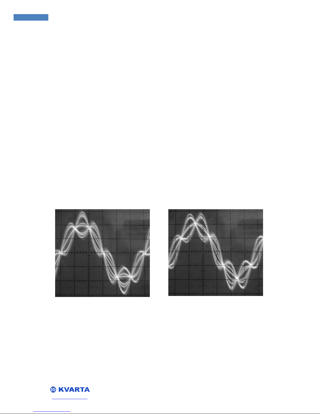
3.4. SYNCHONIZING THE RDS SUBCARRIER
It is desirable to set the RDS subcarrier exactly 90 degrees out of phase with the 19 kHz pilot. This
achieves ‘quadrature’ and slightly reduces the overall modulation of the subcarriers, without redu
cing their actual levels. To envision this, examine the following pictures:
RDS and 19 kHz in synch RDS and Pilot 90° out of phase. The phase of the RDS subcarrier in relation
to the 19 kHz signal is adjustable within the RDS Encoder. You may adjust the phase on the ‘configure
RDS Encoder’ page of the embedded website, or via UDP/TCP terminal with the command
PHASE=<x>
where x is a number between 0 and 359. Query the encoder with
PHASE?
RDS and 19 kHz in synch
RDS and Pilot 90° out of phase
 Loading...