

www.kvarta.net 1/36
1
RDS300/RDS500/RDS1000 User Manual 3.10
RDS300/RDS500/RDS1000
DYNAMIC RDS ENCODERS KVARTA
USER’S MANUAL

www.kvarta.net 2/36
2
RDS300/RDS500/RDS1000 User Manual 3.10
Contents
1. INTRODUCTION ............................................................................................................................... 4
1.1. About KVARTA Ltd. .................................................................................................................. 4
1.2. About RDS and RBDS ............................................................................................................... 4
1.3. Functions of RDS/RBDS. .......................................................................................................... 5
1.4. WHAT ABOUT U.S.? ................................................................................................................. 7
1.5. A FEW WORDS ABOUT PS AND RT .......................................................................................... 7
2. Dynamic RDS Encoder Kvarta .......................................................................................................... 8
2.1. INCLUDED ACCESSORIES ......................................................................................................... 8
2.2. GENERAL SPECIFICATIONS OF THE RDS ENCODER .................................................................. 9
3. GETTING CONNECTED ....................................................................................................................... 10
3.1. CONFIGURING ‘LOOP THROUGH’ OR ‘SIDE CHAIN’ MODE ........................................................ 10
3.2. PHYSICAL INSTALLATION ............................................................................................................ 10
3.3. CONNECTION TO THE BROADCAST CHAIN ................................................................................. 11
3.4. SYNCHONIZING THE RDS SUBCARRIER ....................................................................................... 11
3.5. SETTING THE RDS LEVEL ............................................................................................................. 12
3.6. LED Indication ............................................................................................................................. 12
4. CONFIGURATION AND OPERATION ............................................................................................... 13
4.1. COMMUNICATING THROUGH THE CONSOLE AND COM PORTS ........................................... 13
4.2. COMMUNICATING VIA TCP/IP ............................................................................................... 14
5. ADVANCED FUNCTIONS................................................................................................................. 15
5.1. BROADCASTING TRAFFIC DATA (TMC)* ................................................................................ 15
5.2. BROADCASTING OPEN DATA APPLICATIONS (ODA)* ............................................................ 15
5.3. PAGING APPLICATIONS*........................................................................................................ 16
5.4. BROADCASTING ACCURATE TIME ......................................................................................... 17
6. USING THE UECP PROTOCOL ............................................................................................................. 18
6.1. ABOUT UECP ............................................................................................................................... 18
6.2. UECP AND THE RDS1000 ............................................................................................................ 18
6.3. UECP COMMANDS AND FUNCTIONS* ....................................................................................... 19
7. RDS GLOSSARY ................................................................................................................................... 20
APPENDIX A – PTY, PTYN ....................................................................................................................... 23
APPENDIX B – HOW TO SET UP THE RDS1000 FOR PS NAME OR RADIO TEXT SCROLLING ................. 24
A. UECP configuration. (Expert only) ................................................................................................. 25
B. ASCII configuration. ....................................................................................................................... 26

www.kvarta.net 3/36
3
RDS300/RDS500/RDS1000 User Manual 3.10
APPENDIX C - RDS300/RDS500/RDS1000 ASCII COMMAND SET ......................................................... 29
C.1. HELP COMMANDS ................................................................................................................. 29
C.2. RDS SYSTEM COMMANDS ..................................................................................................... 29
C.3. DSN AND PSN CONFIGURATION ............................................................................................ 30
C.4. Dynamic PS COMMANDS ...................................................................................................... 31
C.5. EON COMMANDS* ................................................................................................................ 32
C.6. ODA COMMANDS* ................................................................................................................ 32
C.7. CLOCK COMMANDS ............................................................................................................... 32
C.8. PAGING COMMANDS* .......................................................................................................... 33
C.9. SCHEDULER COMMANDS* .................................................................................................... 33
C.10. NETWORK COMMANDS .................................................................................................... 34
C.11. COMMUNICATION COMMANDS ....................................................................................... 34
C.12. RT+ COMMANDS* ............................................................................................................. 35
C.13. MONITORING COMMANDS* ............................................................................................. 35
C.14. SNMP COMMANDS* ......................................................................................................... 36
C.15. SPECIAL COMMANDS ........................................................................................................ 36
* Depends on the model RDS300/RDS500/RDS1000

www.kvarta.net 4/36
4
RDS300/RDS500/RDS1000 User Manual 3.10
1. INTRODUCTION
1.1. About KVARTA Ltd.
For more than 20 years, Kvarta has been developing products for Broadcasters and CATV providers.
Our solutions are used by major radio and television broadcasters and regulatory agencies.
Broadcast is our passion. We understand your challenges and have designed many solutions perfectly
adapted to your needs. These include RDS encoders, FM Radio monitors and CATV systems.
KVARTA has a reputation for excellence and innovation among its clients and partners.
1.2. About RDS and RBDS
RDS, or Radio Data System, was developed in Europe in the mid 1980s. It is a method of broadcasting
a low rate data stream on an FM stations’ 57 KHz subcarrier. In many countries around the world,
RDS can actually control the receiver in a car, switching it from frequency to frequency as the vehicle
travels; much like a cellular phone switches from tower to tower. In this mode, a traveler can journey
from one end of a country to another while listening to the same radio program, even though his
radio may seamlessly tune dozens of separate frequencies along the way. RDS can even cause a
receiver to interrupt a CD that is playing to tune in a traffic report, if that is what the listener desires.
The current standards of European RDS broadcasting are reflected in the CENELEC standard EN
50067, which is available on line for research and review, at http://www.rds.org.uk
The KVARTA RDS1000 conforms to all standards and specifications of EN 50067.
RBDS, or Radio Broadcast Data System, is the American standard of RDS data broadcasting, first
introduced into the US in 1993. A significant upgrade of the standards came about in 1998, leaving us
with the standards we have as of this writing (2009). These standards, collectively known as NRSC-4,
are available on line at http://www.nrscstandards.org
.
The data rate for RBDS is small, by today’s broadband and T1 standards. The overall data rate is less
than 1,200 bits per second. A significant number of those bits are used for error correction, so the
usable data rate is a mere 730 bits per second. The data is transmitted in 32 separate ‘groups’, which
are labeled 0A, 0B, 1A, etc. up to group 15B. The purpose of each separate group of data is rigidly
defined, to allow the receivers to know where to ‘look’ for a particular piece of data, and to allow the
most flexibility and possibility of future expansion. Here is a short description of the use of each of
the thirty two groups. If you didn’t already know, ODA stands for Open Data :

www.kvarta.net 5/36
5
RDS300/RDS500/RDS1000 User Manual 3.10
Group
Description
Group
Description
0A
Basic tuning and switching information
8A
Traffic Message Channel or ODA
0B
Basic tuning and switching information
8B
Open Data Applications
1A
Program Item Number and slow labeling
codes
9A
Emergency Warning System or ODA
1B
Program Item Number
9B
Open Data Applications
2A
Radiotext only
10A
Program Type Name
2B
Radiotext only
10B
Open Data Applications
3A
Applications Identification for ODA
11A
Open Data Applications
3B
Open Data Applications
11B
Open Data Applications
4A
Clock-time and date
12A
Open Data Applications
4B
Open Data Applications
12B
Open Data Applications
5A
Transparent Data Channels or ODA
13A
Enhanced Radio Paging or ODA
5B
Transparent Data Channels or ODA
13B
Open Data Applications
6A
In House applications or ODA
14A
Enhanced Other Networks information only
6B
In House applications or ODA
14B
Enhanced Other Networks information only
7A
Radio Paging or ODA
15A
Undefined
7B
Open Data Applications
15B
Fast switching information only
The KVARTA RDS/RBDS RDS1000 encoder is designed to be fully compatible with both the European
and American standards, and broadcast of any or all of the data groups is fully user selectable, to
allow the broadcaster to tailor the RBDS data stream to fit their needs.
1.3. Functions of RDS/RBDS.
RDS is a powerful tool for communicating within a network of transmitters, and controlling and
programming the receivers tuned to that network. Although the functions of RDS are almost too
numerous to detail, these are the primary types of data transmitted over RDS/RBS.
1. The PI, or Program Identification, code. This is a hexadecimal code that identifies a
particular program. This is a required item, as the PI code acts as the digital identification for
your station. In Europe and other countries, the PI code is assigned by the authorities; in the US it
can be calculated by using your stations’ call letters, provided you have a four-letter set. See the
PI section of Appendix A for the calculation, For three letter calls, the PIs have been assigned a
separate set of hex codes that are listed in the RBDS Standard (NRSC-4), also available on line.
The PI code is transmitted in each of the 32 possible groups of RBDS data.
2. The PTY, or Program Type, code. This is a numerical code that labels your format, the type of
programming carried on your station. Be it Top 40, Rock, Classical, Religious or Talk, there is a
code for you (or at least something close). The transmission of this code will allow the listener to
search the FM band for a particular format, instead of by frequency. The codes have been
defined and are listed in the ‘PTY’ section of Appendix A. BEWARE - the PTY codes for the
European (CENELEC) standard are different from those defined by the United States standard
(NRSC), so be certain you’re looking at the right part of the table to broadcast the correct code.
3. The PTYN, or Program Type Name. Just 8 characters.

www.kvarta.net 6/36
6
RDS300/RDS500/RDS1000 User Manual 3.10
4. The M/S flag. A simple ‘yes’ or ‘no’ type flag to indicate whether a stations’ programming is
primarily Music or Speech.
5. The TP, or Traffic Program, flag. This is an indication of whether your station carries traffic
information on a regular basis.
6. The TA, or Traffic Announcement, flag. This is a more critical indicator that says to the
receiver “We are broadcasting a traffic report right now!” WARNING! There are strict
regulations on the use of this flag! If a receiver is set to respond to this flag, it can actually force
the tuner to a new station or interrupt a CD or cassette to hear the traffic information! It is illegal
to have this flag set to ‘on’ if your station is not currently broadcasting traffic information!
7. Clock Time. Allows a receiver to display a time generated by a KVARTA encoder. For more on
the use of this feature, see the ‘Broadcasting Accurate Time’ section under ‘Advanced Functions’.
8. ODA, or Open Data Applications. Just what it says, use of part of the RDS/RBDS data stream
to send any type of data you like, for whatever purpose you desire. Many stations are finding this
application has the potential to generate additional revenue.
NOTE: Use of ODA applications requires obtaining an Application Identification Code (AID). This code
will be broadcast in the 3A groups and identifies the type of application used to transmit data in the
ODA groups.
9. PS, or Program Service, code. This (along with Radio text) is the part of the RDS data that
actually displays alphanumeric information on the listeners’ radio.
10. RT, or Radio Text, code. Another alphanumeric type display. Maximum 64 characters.
11. PIN, Program Identification Number.
The transmitted Programme Item Number code will be the scheduled broadcast start time and
day of month as published by the broadcaster.
12. DI, Decoder Identification. Rarely used, but tells the receiver to decode the broadcast as a
stereo or mono signal. Also can alert the receiver that the PTY codes are dynamic and may
change throughout the day.
13. AF - The Alternate Frequency function is one of the most important. This is a broadcast
of a list of other frequencies that are carrying the same program using the same PI code. A
receiver, acting on the information in the AF list, will continuously sample the other optional
frequencies available, and when it discovers one that is better than the frequency currently
tuned, it automatically tunes the new frequency. Then, from the AF list being broadcast on the
new frequency, it starts sampling others, and so on. Thus, a listener can hear the same program
over a very wide geographic area, with the AF lists and the receiver determining what
frequencies can be used for any given point in that area.
14. EON, or Extended Other Networks. A method of encoding and transmitting AF, PI, and PTY
codes for other networks and programs, usually co-owned with the primary program. This is a
way for Networks that are providing several programs over a geographic area to pre-load the
receivers with information that will allow tuning to any of their alternate programs should the
primary program signal become weak.
15. LINK - A way to link multiple encoders on a network.
16. SLC, or Slow Labeling Codes. Allows programming receivers to accept widely diverse types of
RDS application. Broadcast in RDS Group 1.
17. TDC - Transparent Data Channel, for transmitting diverse RDS data. Group 5.

www.kvarta.net 7/36
7
RDS300/RDS500/RDS1000 User Manual 3.10
18. TMC – The Traffic Message Channel is used for sending real time information on traffic
conditions and road hazards to cars equipped with the appropriate receivers.
19. EWS – The Emergency Warning System, broadcast in RDS group 9.
20. IH - In House – reserved for the broadcaster’s internal use. RDS Group 6.
21. Free Format Groups - Another type of Open Data Application.
22. Standard Paging – Message transmission
23. EPP Paging – Message transmission system that supports the Enhanced Paging Protocol.
24. A.R.I. On/Off – a command only used on certain European national radio networks. Not
supported by the RDS1000.
1.4. WHAT ABOUT U.S.?
In the United States, with a very few exceptions, broadcasters do not want to cause their listeners’
receivers to change frequency. And most automotive receivers on the road in the U.S. have only the
most rudimentary RBDS capabilities. So in America, broadcasters are primarily concerned with using
RBDS to transmit limited types of data: the PI, PTY, and PTYN codes, the M/S, TP and TA flags,
perhaps Clock Time, ODA or (increasingly) TMC. But the most prevalent use of RBDS is the
transmission of dynamic PS and RT, which actually display alphanumeric information on the front
panel of the listeners’ radios.
1.5. A FEW WORDS ABOUT PS AND RT
PS (Program Service name) and RT (Radio Text) are very similar. The displays on most radios are
limited to eight characters, but the powerful scrolling features of KVARTA encoders allow display of
PS and RT text of up to sixty-four characters, moving the text across the screen of the receiver, either
a few characters at a time or by entire words. Most automotive receivers display only (or mostly) PS
text, home receivers tend to primarily display Radio Text. The two can be programmed to display
separate streams of text, but most broadcasters choose to have them both display identical
information, to make sure all receivers are displaying the same thing. It should also be noted that the
moving or ‘scrolling’ type of display of PS has been banned in some countries as a potential
distraction to drivers. Some municipalities and/or states in the US have considered such a ban as
well. Distractions notwithstanding, scrolling PS is a powerful, flexible way to display information to
the listener. Stations commonly interface their encoders with their automation systems to
automatically show the name of the artist and title of the current song. When not broadcasting
music, the scrolling PS can display the name of the station, the current host or program, or the name
of a special guest. Stations have even used their scrolling PS to give their listeners traffic information
or the latest news headlines. Other potential uses lie in contesting or even advertisements. The uses
are nearly limitless, and the encoders from KVARTA gives you the power and flexibility to exploit
those uses, both now and well into the future. More details in paragraph 4 and Appendix B.

www.kvarta.net 8/36
8
RDS300/RDS500/RDS1000 User Manual 3.10
2. Dynamic RDS Encoder Kvarta
2.1. INCLUDED ACCESSORIES
In your package, you should have received:
• Your RDS encoder
• One AC main power cord
• One shielded RS-232 serial data cable
• One CD-ROM containing software, manuals.
www.kvarta.net 9/36
9
RDS300/RDS500/RDS1000 User Manual 3.10
2.2. GENERAL SPECIFICATIONS OF THE RDS ENCODER
Communication ports
Serial ports
COM1 (UECP and ASCII configuration)*
Ethernet
100baseT – Web Server and UDP/TCP/SNMP*
RDS subcarrier
Level (digitally controlled)
Software controlled from -60dBm to 0dBm (1 to 2500 mV P-P)
Spectrum
complies with CENELEC EN50067 standard
Waveform
100% digitally generated
Sampling rate
912 KHz
Bypass
0dB (automatic bypass in case of power failure)
Bandwidth
+/- 2.4 kHz (@-55dB)
S/N
below 54 kHz (≥-75dB)
Linear distortion
≤ 0.5 dB
Output impedance
100 Ω
Input impedance
> 600 Ω
Pilot Synchronization
Synchronization
Automatic (internal or external if available)
Input level
-50dBu to +12dBu
Pilot Frequency
19kHz, +/- 2Hz
Phase
adjustable from 0° to 360°
MPX signal
RDS signal input and output
Unbalanced, BNC connector
Synchroniztion
Automatic pilot tone synchronization
Bypass feature
Retransmission of the MPX input signal to the MPX output (+RDS)
Phase
Controlable digitally
Power Supply
Supply voltage
115V / 230V
Voltage tolerance
+/- 10%
Main AC frequency
45-65 Hz
Fuse
1A T
Consumption
10 VA
Mechanical aspects
Height
1U (44,5 mm)
Width
483 mm
Depth
220 mm
Net weight
4 kg
TCP/IP
Embedded Web Server
Available
UDP/TCP
UECP/ASCII/SNMP*
Front panel indication
Leds
Power supply, RDS Output, LAN OK, Pilot Sync
RDS Decoder
COM1
Monitoring of broadcasted RDS data. Use RDS Decoder 3.0 software
provided by www.esslinger.de .
TCP
Full monitoring over Ethernet only RDS500 and RDS1000 using rdsspy.
* SNMP and UECP support for RDS500 and RDS1000. Partial UECP support for RDS300.

www.kvarta.net 10/36
10
RDS300/RDS500/RDS1000 User Manual 3.10
3. GETTING CONNECTED
3.1. CONFIGURING ‘LOOP THROUGH’ OR ‘SIDE CHAIN’ MODE
Before installing the RDS Encoder in an equipment rack, you should determine how it will
interface with your other equipment, particularly the exciter or pilot transmitter. There are two ways
to connect the RDS Encoder encoder to your exciter, ‘Loop Through’ and ‘Side Chain’.
In ‘Loop Through’ mode, the multiplex/composite signal passes through the RDS Encoder on
its way to the exciter, with the RDS Encoder adding the RDS modulation to the signal. The switch
must be at RDS+MPX.
In ‘Side Chain’ mode, the RDS Encoder’s output is separate from the multiplex/composite
signal, and connects to the exciter at a designated RDS/57 KHz subcarrier input. The switch must be
at RDS position.
Whichever way you choose to connect you just have to switch the position of the switch in
the rear end.
3.2. PHYSICAL INSTALLATION
Before installing the RDS Encoder, particularly if it is to be placed at a remote location, it is a
good idea to do some setup and familiarization in the comfort of the shop. Most of the RDS
Encoder’s parameters can be configured in advance and ‘locked in’ so that the installation at the
remote site will be a simple matter. This is especially good advice if the RDS Encoder is to be
interfaced with an automation system for automatic display of artists’ names and song titles. It is far
easier to configure and debug the various communication and syntax issues with the automation and
encoder in close proximity, rather than having to run from studio to transmitter site several times
until your settings are correct!
The RDS300/RDS500/RDS1000 is one rack unit in height, and generates no abnormal levels
of heat or electrical interference, so the only factors that influence the choice of mounting location
are ease of connection with the exciter, the LAN (if used) and any other devices or cables that need
to interface with the RDS Encoder. Kvarta RDS Encoders were designed to be installed at an FM
transmitter site; therefore it meets and exceeds criteria and levels for RF interference that are
considerably worse than required.
The RS-232 ports are protected by 15V Zener diodes, nevertheless KVARTA strongly advises
against connecting the RDS Encoder to any cable that runs outside the building where the encoder is
installed! The RDS Encoder does rely on natural convection for cooling, so make sure that the
ventilation openings on the top and sides will not be blocked when installing it.
▲ WARNING The RDS Encoder’ ground is close to the chassis potential, you must make sure the unit
is reliablygrounded, either through the third pin of the main AC power cord, or through the
grounding terminal on the rear panel. Serious problems may arise if the unit is grounded only
through the ground pins of the communications ports or the ground of a BNC connector.
▲ WARNING Check the voltage setting on the fuse holder next to the AC power input! Make sure
that the setting is appropriate for the common AC voltage in your area.
www.kvarta.net 11/36
11
RDS300/RDS500/RDS1000 User Manual 3.10
3.3. CONNECTION TO THE BROADCAST CHAIN
If the RDS Encoder is to be used in ‘Loop through’ mode, connect the output of your stereo
generator/multiplexer to the ‘MPX IN / SYNC’ jack of the encoder, using 75 ohm coaxial cable. Then
connect the ‘MPX OUT’ jack of the RDS Encoder to the composite/multiplex input of your exciter or
pilot transmitter.
If you have chosen to install the RDS Encoder in the ‘Side Chain’ configuration, simply
connect the ‘RDS IN/OUT’ jack of the encoder to the 57 kHz SCA or RDS jack on the pilot/exciter. You
may also connect from the ‘MPX OUT’ jack of the RDS Encoder; providing you are certain you have
the internal jumpers configured properly to block the main composite/MPX signal from also
appearing at this jack (see section 3.1.1).
NOTE: If you have configured your RDS Encoder for ‘Side Chain’ operation, you should provide a
composite or 19kHz feed from your stereo generator to the RDS Encoder’s ‘MPX IN’. You may
accomplish this with a simple ‘T’ connector in the coaxial path between the stereo
generator/multiplexer and your exciter/pilot transmitter. The RDS Encoder presents no load or other
damaging characteristics to the signal.
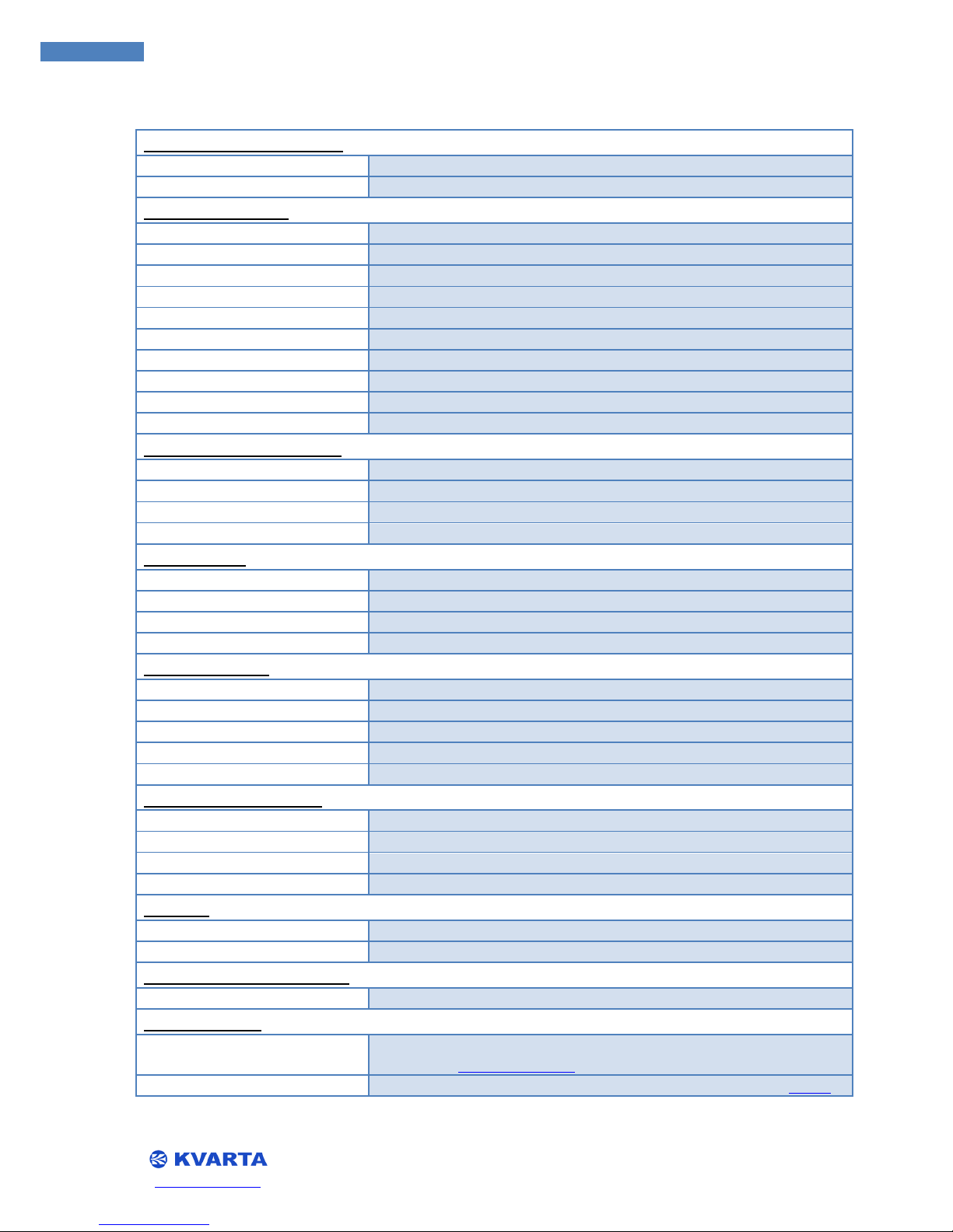
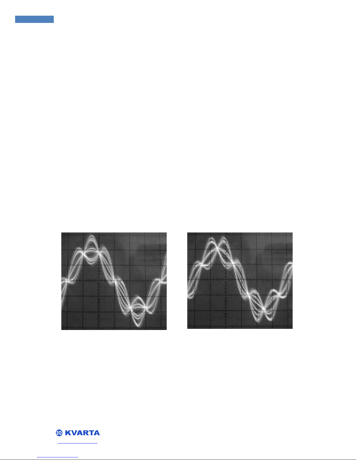
3.4. SYNCHONIZING THE RDS SUBCARRIER
It is desirable to set the RDS subcarrier exactly 90 degrees out of phase with the 19 kHz pilot. This
achieves ‘quadrature’ and slightly reduces the overall modulation of the subcarriers, without redu
cing their actual levels. To envision this, examine the following pictures:
RDS and 19 kHz in synch RDS and Pilot 90° out of phase. The phase of the RDS subcarrier in relation
to the 19 kHz signal is adjustable within the RDS Encoder. You may adjust the phase on the ‘configure
RDS Encoder’ page of the embedded website, or via UDP/TCP terminal with the command
PHASE=<x>
where x is a number between 0 and 359. Query the encoder with
PHASE?
RDS and 19 kHz in synch
RDS and Pilot 90° out of phase

www.kvarta.net 12/36
12
RDS300/RDS500/RDS1000 User Manual 3.10
the RDS Encoder will respond with the current value for its phase differential. By the default factory
setting, the RDS Encoder will automatically detect if there is a 19 kHz signal present at the ‘MPX IN’
jack and synchronize the RDS subcarrier to it. If there is no signal present, the RDS Encoder will synch
to its own internal 19 kHz clock.
PILOT?
will return a 1 if the RDS Encoder detects a pilot signal at the ‘MPX IN’ jack, 0 if none is detected.
3.5. SETTING THE RDS LEVEL
The output level of the RDS Encoder that determines the modulation of the RDS subcarrier is
variable in 1 millivolt increments from 0 to 2500 nVpp. Due to variations in other transmitting
equipment in the broadcast chain, it is impossible to accurately predict what level of modulation will
occur with a given output level.
The best way to ensure accurate adjustment of the RDS injection level is with a monitor or
measuring device that is capable of directly read the modulation of the 57 kHz subcarrier.
An alternate, but less accurate method is to temporarily disable the main and stereo
modulation, by interrupting the audio. Then, a modulation monitor that is sensitive enough can
measure the modulation of the RDS subcarrier alone.
KVARTA recommends an RDS injection level that corresponds to a carrier deviation of
approximately 4 kHz, or 4 -5 percent modulation. In the USA, the FCC allows an FM broadcast station
an extra 5% of total modulation for each subcarrier that is active, up to a maximum of 110% total
modulation. You can adjust the RDS output level of the RDS Encoder on the ‘configure RDS encoder’
page of the embedded website, or via terminal or telnet session with the command: ‘LEVEL=<x>’,
where x * is a number between 0 and 2500. ‘LEVEL?’ returns the currently configured value for RDS
output level. ‘RDS=1’ will enable RDS broadcast, ‘RDS=0’ will disable it.
3.6. LED Indication
POWER – Indicates that power supply is available.
SYNC – Indicates that 19 KHz pilot synchronization is working. (ASCII command: PILOT?)
OK – Indicates LAN connection ON/OFF.
RDS OUT – Indicates that RDS data is generated and available at the output. NOTE: RDS generation
can be stopped using command RDS=1/0.

www.kvarta.net 13/36
13
RDS300/RDS500/RDS1000 User Manual 3.10
4. CONFIGURATION AND OPERATION
4.1. COMMUNICATING THROUGH THE CONSOLE AND COM PORTS
Configuration requires that you establish communication with the RDS Encoder. The first and
simplest way to do that is through the COM port. There is one of the very common RS-232 COM
ports on the RDS Encoder: COM1 with female jack on the rear panels.COM1 DSR(pin 6 ) and RI (pin 9)
are connected to RDS Data and RDS Clock, thus COM1 can be used for RDS decoding using RDS
Decoder 3.0 software which is downloadable at www.esslinger.de
.
The default settings for all the COM ports are 9600 baud, 8 data bits, no parity, and 1 stop bit.
(9600, 8, n, 1) Flow control is none. If you are connecting through COM1, UDP/TCP, you should
enter the command ‘ECHO=1’ to activate the echo function so you can see the characters you are
typing.
To open a terminal session through the COM ports, simply connect a computer to the RS-232
connector (using a serial/USB port if you don’t have an RS-232 on your computer) and open a
terminal program, such as HyperTerminal or HerculesTerminal
. If you are connected when you power
up the RDS Encoder, you will see a welcome screen like this:
▲ WARNING If you are using the USB port do not unplug the cable when the virtual COM port is
opened by an application. You must first close the COM port before unplugging the USB.
*****************************************
* RDS ENCODER KVARTA - RDS1000
* Firmware Version
: 3.00A (14/04/2011)
* http://www.kvarta.net
* tel : +359 (0)62 640914
*****************************************
There are two commands that list configured information. For more information regarding the
commands see APPENDIX C
:
RDS?
Lists all configured RDS information. PI, PS, TA, TP, PTY ….
ipconfig?

www.kvarta.net 14/36
14
RDS300/RDS500/RDS1000 User Manual 3.10
Returns all configured information regarding the ethernet connection: MAC, IP, MASK, Gateway,
DHCP,PORT, FILTER, USER, WEB_SERVER.
If you want to change the PS string, just write the following command:
PS=<8 length >
Where n is any alphanumeric character or characters, up to 8 characters in length. And the command
for activating the RDS output of the RDS Encoder would read:
rds=<x>
Where x is either 1, which activates RDS, or 0, which disables the RDS output.
NOTE: To submit the command you need to press <Enter>(These ascii symbols are accepted for end
of an ascii command : CR+LF,CR,LF)
To see what is currently configured you have to write the command followed by a question mark. For
example:
PI?
The RDS Encoder must return as a response the configured PI code. For example: PI=0000.
NOTE: After you hit <Enter> the unit will respond with a plus sign if it accepts the new configuration
command and an exclamation mark if the command is not acceptable.
4.2. COMMUNICATING VIA TCP/IP
The most intuitive way to set up the RDS Encoder is to access the embedded website through a
TCP/IP connection. You can do this through a hub, switch, or router using standard LAN and Ethernet
protocols, or you can connect your computer directly to the RDS Encoders Ethernet port.
NOTE: To connect a computer directly to the RDS Encoder, you must use a ‘crossed’ Ethernet cable,
and the computer’s IP address must be in the same range as the RDS Encoders. Meaning the first
three groups of numbers in the IP address (xxx.xxx.xxx.xxx) must be the same! (right by default).
To connect to the embedded website, open an Internet browser (IE, Mozilla, Netscape, etc) and
enter the IP address of the RDS Encoder. The default address as shipped from the factory is
192.168.2.3, but you may alter that as you wish. You can change the IP address through the website
page or with the command:
IP=<xxx.xxx.xxx.xxx>
After you hit <Enter> the unit will respond with the plus sign. Then enter the command ‘reset’ (or
cycle the power) and the RDS Encoder will reboot with the new IP address active.
NOTE: The new IP will not be active until the unit is restarted. If you have changed the IP using a
Telnet session, you will have to reopen a new session at the new IP address.

www.kvarta.net 15/36
15
RDS300/RDS500/RDS1000 User Manual 3.10
5. ADVANCED FUNCTIONS
5.1. BROADCASTING TRAFFIC DATA (TMC)*
The Traffic Management Channel (TMC) is a method of communicating real time traffic
information to vehicles equipped with the proper receivers to decode and display that data.
Prevalent in many European countries, TMC data can help drivers select the best routes on their
journey, advise motorists of slowdowns or accidents on the road ahead, and maximize efficient use
of a fleet of vehicles. The data streams and protocols used for TMC can vary somewhat, but one
constant is that TMC applications utilize the 8A group of RDS data. Frequently, the volume of TMC
data requires that it be split and broadcast in a number of different RDS groups to ensure delivery of
accurate data in a timely manner.
To enable broadcast of the 8A groups, go to the ‘configure RDS encoder’ page of the RDS
Encoders embedded website. Enter at least one 8A group in the ‘Group Sequence’ box near the
bottom of the page, and click ‘Save’ to save your changes.
For further information and support on TMC applications, contact us.
*Only RDS1000
5.2. BROADCASTING OPEN DATA APPLICATIONS (ODA)*
The RDS Encoder encoder supports the broadcast of Open Data Applications in RDS. There are
several modes of ODA - FIFO, Cyclic, Burst mode, Spinning Wheel mode, Extremely urgent and
Immediate. These modes are specified in the RDS standard EN50067 and in the UECP protocol EBUUECP SPB490 version.
To configure an "ODA" application
An ODA application is defined by its AID code and by the type of group used, these two
parameters appear in the 3A groups used for service locating. The command
ODA.gv.AID=<aaaa>
can be used to define the AID code aaaa associated to the group type, gv=3A, 3B, 4B, 5A, 5B, 6A,
6B,7A, 7B, 8A, 8B, 9A, 9B, 10B, 11A, 11B, 12A, 12B, 13A or 13B.
The 3A type groups and the type of group used for the ODA application must be included in the
'group sequence' defined by the command
DSN(d).GS=<g1,g2,g2,…gn>
where d = 1 to 6 specifies the assigned DSN, n<=252 and g1,g2,..gn = 0A, 0B, 1A,…to 15A. (The values
4A, 14B and 15B are prohibited).
The broadcasting of the 3A type groups is managed, according to the type of group associated to an
AID code, by the parameter
SEQ3A=<U1,U2,…U16>

www.kvarta.net 16/36
16
RDS300/RDS500/RDS1000 User Manual 3.10
Un defines the type of group used by the ODA application, U1, U2,…Un= 3A (specific case), 3B, 4B,
5A,5B, 6A, 6B, 7A, 7B, 8A, 8B, 9A, 9B, 10B, 11A, 11B, 12A, 12B, 13A, 13B.
The messages included in the 3A groups (block C) are defined by the commands
ODA.gv.MSG=<bbbb> and ODA.gv.MSG2=<bbbb>
where gv=3A, 3B, 4B, 5A, 5B, 6A, 6B, 7A, 7B, 8A, 8B, 9A, 9B, 10B, 11A, 11B, 12A, 12B, 13A or 13B; and
bbbb=0000 to FFFF represents the message. A Timeout (maximum inactivity delay) can be defined by
the command ‘ODA.gv.TO=<t> ‘ where gv=3A, 3B, 4B, 5A, 5B, 6A, 6B, 7A, 7B, 8A, 8B, 9A, 9B, 10B,
11A, 11B, 12A, 12B, 13A or 13B; and t = 0(function disabled) to 255 in minutes.
The two transmission modes known as "BURST" and "SPINNING WHEEL" are respectively defined
by the commands:
ODA.gv.REPEAT=<n> , where n = repetition number,
ODA.gv.SPACE=<x> , where x = minimum number of groups between two gv type groups,
ODA.gv.NB=<n> , where n = number of windows defined in a one minute cycle,
ODA.gv.WINDOW=<t> , where t = in seconds the inactivity period in the cycle, and
ODA.gv.DELAY=<d>, where d defines (in seconds) the delay between the start of a minute
(second =0)
and the start of the active period, and gv=3B, 4B, 5A, 5B, 6A, 6B, 7A, 7B, 8A, 8B, 9A, 9B,
10B, 11A, 11B,12A, 12B, 13A or 13B
*Only RDS1000
5.3. PAGING APPLICATIONS*
The RDS Encoder encoder allows the extended use of Paging in RDS. To start with, it supports the
'standard' paging system i.e. the one which is specified in the RDS standard EN50067 dated 1992.
A second paging process called "EPP" (Enhanced Paging Protocol) is also available, compatible
with and improving on standard paging. If you have interest in using EPP, please contact us.
To configure a "paging" application
Insert 7A type groups in the group sequence using the command
DSN(d).GS=<g1,g2,g2,…gn>
where d = 1 to 6 specifies the assigned DSN, n<=252 and g1,g2,..gn = 0A, 0B, 1A,…to 15A. (The
values 4A, 14B and 15B are prohibited). You may also enter 7A groups in the ‘Group Sequence’ box
on the ‘configure RDS Encoder’ page of the RDS Encoders embedded website.
The number of 7A type groups present in the group sequence must guarantee the possibility of
broadcasting at least one to two 7A groups per interval for numeric paging and twenty 7A groups for
the 80 character text paging (an ‘interval’ represents approximately 66 groups).
Define the value of the GRPD code with the command

www.kvarta.net 17/36
17
RDS300/RDS500/RDS1000 User Manual 3.10
DSN(d).GRPD=<I>
with i=0 to 7.
*Only RDS1000
5.4. BROADCASTING ACCURATE TIME
If you choose to configure your RDS Encoder to broadcast local time as part of the RDS data,
there are several steps to enable this feature. The first is to enable broadcast of RDS data group 4A,
which is designated for transmitting clock and calendar data. You may do this on the internal website
: on the RDS Configuration page, select the flag that enables CT transmission.Via telnet or a terminal
session, you can use the commands:
CT=1
You do not need to add 4A group in the group sequence, because setting CT=1 enables the 4A group
automatic transition on every minute despite the group sequence. Here is an example of setting
clock time using ASCII command.
CT_SET=01/01/2009 09:12:32 +4
The date and time format is : dd/mm/YYYY hh:mm:ss +/-offset ,where the date time is the UTC and
the offset is in +/- 30 minutes units. The above example is configuring +2 hours for local time offset.
To view the configured time, use the command:
CT_SET?

www.kvarta.net 18/36
18
RDS300/RDS500/RDS1000 User Manual 3.10
6. USING THE UECP PROTOCOL
6.1. ABOUT UECP
As RDS progressed and grew in Europe, a need was seen to have some form of standardization
amongst different RDS encoders from various manufacturers. The output protocol of the encoders to
the receivers in the listening area was already defined, but what was needed was a standard for
communication and control of a network of disparate encoders with a single protocol. UECP, the
Universal Encoder Communication Protocol, was created for this purpose, and finalized by the
European Broadcasting Union (EBU), as document SPB490. The protocol was accepted by CENELEC.
6.2. UECP AND THE RDS1000
The RDS1000 is fully UECP capable, and conforms to all of the recommendations of the EBU-UER
SBP490 document and all of the CENELEC standards regarding UECP. The UECP protocol establishes a
way to address encoders in groups or individually, and sets standard methods for unidirectional and
bidirectional communication, software models within the encoders, mechanical specifications, data
formats, message structure, message codes, handling of RDS data, including ODA, and remotely
configuring encoders. There is a great deal of information to be understood to implement use of
UECP on your encoders, and there are other, better documents that contain the information specific
to UECP. That being said, there follows a list of some of the more common UECP commands that are
accepted by the RDS1000.
NOTE: The manufacturer’s specific command, 2D, followed by the manufacturer designation KV
will allow you to send any valid command to the RDS1000 via UECP.
Example : send of a valid character chain (PS_Text=…… in UECP).

www.kvarta.net 19/36
19
RDS300/RDS500/RDS1000 User Manual 3.10
6.3. UECP COMMANDS AND FUNCTIONS*
* Full UECP support only RDS1000
RDS Message commands
PI
01
PS
02
PIN
06
DI
04
TA/TP
03
MS
05
PTY
07
PTYN
3E
RT
0A
AF
13
EON-AF
14
Slow Labeling
1A
Link Data
2E
Paging commands
Paging call, no message
0C
Page, numeric message (10 dig)
08
Page, numeric message (18 dig)
20
Page, alphanum mess (80char)
1B
International num pate (15 dig)
11
Intern. page with function mess
10
Transmitter net group designatn
12
EPP transmitter info
31
EPP call, no message
32
EPP call, alphanum message
33
EPP call, numeric message
34
EPP call, functions message
35
Control and setup commands
Site address
23
Encoder address
27
Make PSN list
28
PSN enable/disable
0B
TA control
2A
EON – TA control
15
Reference input select
1D
Data set select
1C
Group Sequence
16
Group variant code sequence
29
Extended group sequence
38
PS character code table selection
2F
Open Data Application commands
ODA config and short message
40
ODA gp. usage sequence
41
ODA free format group
42
ODA rel. priority gp sequence
43
ODA ‘burst mode’ control
44
ODA ‘spinning wheel’ timing
45
Transparent data commands
TDC
26
EWS
2B
IH
30
TMC
30
Free-format group
24
Clock setting and control
Real time clock
0D
Real time clock correction
09
Clock Time (CT) on/off
19
RDS adjustment and control
RDS on/off
1E
RDS phase
22
RDS Level
0E
Bi-directional commands
Message acknowledgment
18
Request message
17
Specific message commands
Manufacturer’s specific
command
2D
Communication settings
COM port mode
3B
COM port speed
3C
COM port timeout
3D
Encoder access right
3A
Communication mode
2C

www.kvarta.net 20/36
20
RDS300/RDS500/RDS1000 User Manual 3.10
7. RDS GLOSSARY
AF - Alternative Frequencies list The list(s) of alternative frequencies give information on the various
transmitters broadcasting the same program in the same or adjacent reception areas, and enable
receivers equipped with a memory to store the list(s), to reduce the time needed for switching to
another transmitter. This facility is particularly useful in the case of car and portable radios.
CT - Clock Time and date Time and date codes should use Coordinated Universal Time (UTC) and
Modified Julian Day (MJD). If MJD = 0 the receiver should not be updated. The listener, however, will
not use this information directly and the conversion to local time and date will be made in the
receiver's circuitry. CT is used as time stamp by various RDS applications and thus it must be
accurate.
DI - Decoder Identification and dynamic PTY indicator These bits indicate which possible audio
modes are appropriate for use with the broadcast audio and to indicate if PTY codes are switched
dynamically.
ECC - Extended Country Code RDS uses its own country codes. The first most significant bits of the PI
code carry the RDS country code. Their four bit coding structure only permits the definition of 15
different codes, 1 to F (hex). Since there are much more countries to be identified, some countries
have to share the same code, which does not permit unique identification. Hence there is the need
to use the Extended Country Code. The ECC consists of eight bits.
EON - Enhanced Other Networks information This feature can be used to update the information
stored in a receiver about program services other than the one received. Alternative frequencies, the
PS name, Traffic program and Traffic Announcement identification as well as program Type and
program Item Number information can be transmitted for the other service. The relation to the
corresponding program is established by means of the relevant program Identification. Linkage
information, consisting of four data elements, provides the means by which several program services
may be treated by the receiver as a single service during times a common program is carried. Linkage
information also provides a mechanism to signal an extended set of related services.
EWS - Emergency Warning System The EWS feature is intended to provide for the transmission of
warning messages. These messages will be broadcast only in cases of emergency and will only be
evaluated by special receivers.
IH - In House application This refers to data to be decoded only by the broadcast operator. Some
common examples are identification of transmission origin, remote switching of networks and paging
of staff. The applications of coding may be determined by each individual operator.
ODA - Open Data Applications The Open Data Applications feature allows data applications, not
previously specified in EN 50067, to be conveyed in a number of allocated groups in an RDS
transmission. The groups allocated are indicated by the use of type 3A group, which is used to
identify to a receiver the data application in use in accordance with the registration details.
PI - program Identification This information consists of a code enabling the receiver to distinguish
between countries, areas in which the same program is transmitted, and the identification of the
program itself. The code is not intended for direct display and is assigned to each individual radio
program or transmitter (US), to enable it to be distinguished from all others. One important

www.kvarta.net 21/36
21
RDS300/RDS500/RDS1000 User Manual 3.10
application of this information would be to enable the receiver to search automatically for an
alternative frequency in case of bad reception of the program to which the receiver is tuned; the
criteria for the change-over to the new frequency would be the presence of a better signal having the
same program Identification code.
PIN - program Item Number The code should enable receivers and recorders designed to make use
of this feature to respond to the specific program(s) that the user has pre-selected. Use is made of
the scheduled program time, to which is added the day of the month in order to avoid ambiguity.
PS - program Service name This is the label of the program service consisting of not more than eight
alphanumeric characters which is displayed by RDS receivers in order to inform the listener what
program service is being broadcast by the station to which the receiver is tuned. An example for a
name is "Radio 21". The program Service name is not intended to be used for automatic search
tuning and must not be used for giving sequential information.
PTY - program Type This is an identification number to be transmitted with each program item and
which is intended to specify the current program Type within 31 possibilities. This code could be used
for search tuning. The code will, moreover, enable suitable receivers and recorders to be pre-set to
respond only to program items of the desired type. The last number, i.e. 31, is reserved for an alarm
identification which is intended to switch on the audio signal when a receiver is operated in a waiting
reception mode.
PTYN - program TYpe Name The PTYN feature is used to further describe current PTY. PTYN permits
the display of a more specific PTY description that the broadcaster can freely decide (eg PTY=4: Sport
and PTYN: Football). The PTYN is not intended to change the default eight characters of PTY which
will be used during search or wait modes, but only to show in detail the program type once tuned to
a program. If the broadcaster is satisfied with a default PTY name, it is not necessary to use
additional data capacity for PTYN. The program Type Name is not intended to be used for automatic
PTY selection and must not be used for giving sequential information.
RP - Radio Paging The RP feature is intended to provide radio paging using the existing VHF/FM
broadcasts as a transport mechanism, thereby avoiding the need for a dedicated network of
transmitters. Subscribers to a paging service will require a special pocket paging receiver in which the
subscriber address code is stored.
RT – RadioText This refers to text transmissions coded in accordance to the RDS/RBDS standards,
primarily addressed to consumer home receivers, which would be equipped with suitable display
facilities.
TA - Traffic announcement identification This is an on/off signal to indicate when a traffic
announcement is on air. The signal could be used in receivers to: 1. switch automatically from any
audio mode to the traffic announcement 2. switch on the traffic announcement automatically when
the receiver is in a waiting reception mode and the audio signal is muted 3. switch from a program to
another one carrying a traffic announcement, according to possibilities available through EON. After
the end of the traffic announcement the TA must be restored to ‘OFF’.
TDC - Transparent Data Channels The transparent data channels consist of 32 channels, which may
be used to send any type of data.

www.kvarta.net 22/36
22
RDS300/RDS500/RDS1000 User Manual 3.10
TMC - Traffic Message Channel This feature is intended to be used for the coded transmission of
traffic information. The coding is separately defined by a set of standards issued by CEN [ENV 123131 and prENV 12313-2].
TP - Traffic Program identification This is a flag to indicate that the tuned program carries traffic
announcements. The TP flag must only be set on programs that dynamically switch on the TA
identification during traffic announcements. The signal shall be taken into account during automatic
search tuning.

www.kvarta.net 23/36
23
RDS300/RDS500/RDS1000 User Manual 3.10
APPENDIX A – PTY, PTYN
Following is a list of the European (RDS Program Type,CENELEC) and American (RBDS
Program type, NRSC) format codes for configuring your PTY and PTYN. Don’t worry if there’s not an
exact match, just find one that’s close.
PTY code
RDS Program type
RBDS Program type
0
No program type or undefined
No program type or undefined
1
News
News
2
Current affairs
Information
3
Information
Sports
4
Sport
Talk
5
Education
Rock
6
Drama
Classic Rock
7
Culture
Adult Hits
8
Science
Soft Rock
9
Varied
Top 40
10
Pop Music
Country
11
Rock Music
Oldies
12
M.O.R. Music
Soft
13
Light classical
Nostalgia
14
Serious classical
Jazz
15
Other Music
Classical
16
Weather
Rhythm and Blues
17
Finance
Soft Rhythm and Blues
18
Children’s programs
Language
19
Social Affairs
Religious Music
20
Religion
Religious Talk
21
Phone In
Personality
22
Travel
Public
23
Leisure
College
24
Jazz Music
Unassigned
25
Country Music
Unassigned
26
National Music
Unassigned
27
Oldies Music
Unassigned
28
Folk Music
Unassigned
29
Documentary
Weather
30
Alarm Test
Emergency Test
31
Alarm
Emergency

www.kvarta.net 24/36
24
RDS300/RDS500/RDS1000 User Manual 3.10
APPENDIX B – HOW TO SET UP
THE RDS1000 FOR PS NAME OR RADIO TEXT SCROLLING
The RDS1000 enables to configure the PS name or radio text from different way. The purpose
of this appendix is to explain in details how to configure the equipment to scroll a text.
First of all, remember that scrolling function of PS name or Radio text is not allowed by the
RDS recommendations: “The Programme Service name comprises eight characters, intended for
static display on a receiver. It is the primary aid to listeners in programme service identification and
selection. The use of PS to transmit text other than a single eight-character name is not permitted.
Transmission of a PS name usually takes four type 0A groups, but to allow an instant display of the PS
when a receiver pre-set is selected, the PS name is often stored for subsequent recall from memory
when a programme service is selected. The transmission and reception conditions for PS described
were designed on the basis that PS would generally be invariant. A few transmission operators have
allowed PS to change to reflect the origin of the service, for example when a regional service
switches to a national service. These changes which may occur a few times a day and have a duration
of anything between a few minutes and several hours, are acceptable, but any other dynamic
changes to PS are NOT acceptable and may cause a safety hazard by distracting a vehicle driver. A
similar effect could be experienced with dynamic text transmission of PTYN. As a result, dynamic
PS and PTYN transmissions are expressly forbidden. Similarly RT could also be distracting to a
vehicle driver; therefore the in-vehicle display of RT should normally be disabled and RT display
should be designed for end-user viewing only when manually enabled.”
KVARTA has decided to include a powerful dynamic display of PS and RT in our encoders due
to the growing requests from our customers. Before any dynamic set up be sure that your country
regulation authority allows this.
Programme Service name (PS)
This is the label of the programme service consisting of not more than eight alphanumeric
characters, which is displayed by RDS receivers in order to inform the listener what programme
service is being broadcast by the station to which the receiver is tuned. An example for a name is
"Radio 21". The Programme Service name is not intended to be used for automatic search tuning and
must not be used for giving sequential information.
RadioText (RT) This refers to text transmissions, primarily addressed to consumer home
receivers, which would be equipped with suitable display facilities.
1. Why different configuration of the PS name?
The PS name is really important for the listener it is the simplest way to tune a receiver by
decoding the name of the station (or call letters). For this reason it is absolutely necessary, for radio,
to always broadcast this information. In the RDS1000 you can configure 3 independent PS name.
Static PS name: Call letters of the station in accordance with the RDS recommendation
Eight characters. Stored in EEPROM.

www.kvarta.net 25/36
25
RDS300/RDS500/RDS1000 User Manual 3.10
PS scrolling: Possibility to scroll by characters or by words a text of up to 64 characters.
Instead of the static PS name. Stored in RAM or EEPROM.
Dynamic PS scrolling: Possibility to automatically scroll by characters or by words a text
coming from automation software. Instead of the static PS name . Stored only in RAM.
As there are 3 different way to configure the display of a PS name a hierarchy has been
designed in the RDS Encoder:
1. Dynamic PS scroll. If necessary information feed, the encoder this information is prior to
all the others.
2. PS scroll, second priority of the encoder.
3. Static PS name, less priority. Eight characters label is sending if Dynamic PS scroll or Ps
scroll are not active.
2. How the PS name can be set up?
One way to configure an encoder is with the UECP (Universal Encoder Communication
Protocol). This protocol is used to configure any compliant RDS encoders
This recommendation rules the way to set up the PS name. (EXPERT user) This configuration
mode will also be used if any specific characters or specific typo Arabic, Cyrillic, Greek, are necessary
because:
- The RDS uses character tables (specified in RDS and RBDS standards), which are different
from the DOS or Windows ones. This means that you have to send the correct hexadecimal value,
the encoder doesn't do any "translation".
- Take care that very few receivers recognize "special" characters. Secondly, with ASCII
commands. The RDS Encoder offers the possibility to be configured with ASCII commands. Such
facility should be used when the user doesn’t want or know the UECP protocol and when the
automation software is linked to the encoder via a RS232 connection.
Finally, with the RDS Encoder embedded Web site. RDS Encoder is the first RDS encoder that
offers to be configuring via TCP/IP. Specific web pages have been specially created for the
configuration of the PS and / or RT then information from automation software will be received via
the communication ports.
A. UECP configuration. (Expert only)
By default all com ports have bidirectional spontaneous mode of UECP enabled. The default
com port settings are : 9600,None,8,1 (Baudrate,parity,data bit,stop bit). Use UECP software to send
a static name. If you don’t have UECP software it will be preferable to use ASCII configuration.
STATIC PS configuration with UECP
PS name is set up with UECP MEC 02 . For more detailed information please refer to:
http://www.rds.org.uk/rds98/ebuuecpspecification.htm
PS SCROLL or DYNAMIC PS SCROLL configuration with UECP
UECP enables to send Manufacturers specific commands. As PS scroll is not allowed by the

www.kvarta.net 26/36
26
RDS300/RDS500/RDS1000 User Manual 3.10
recommendation. It will be necessary to use MEC 2D to transmit relevant information to the
encoder.
Any ASCII(text) command can be coded in UECP and can be sent to the encoder. So in order
to configure the PS scroll or Dynamic PS scroll please refer the chapter B to know the exact
command to code.
For example In order to configure PS_text command (see chapter B) the
following MEC 2D should be used:
2D MEC
02-FD MEL
41 Manufacturer designation (K)
5A Manufacturer designation (V)
50 P
53 S
5F _
54 T
45 E
58 X
54 T
3D =
Etc…
Of course this message must be include in a valid UECP frame.
B. ASCII configuration.
The RDS Encoder enables to be configured with simple terminal software. The terminal must
be set up with the following parameters for the PC communication port.
Baud rate : 9600 Bps
Data Bits: 8
Parity: None
Stop bit: 1
Flow control: None
Once the terminal is correctly configured, switch on the encoder to display the equipment
auto test.
STATIC PS configuration with CONSOLE mode
The command to set up the Static PS name of the active PSN is PS=……..
The “PS=” command value is stored in a EEPROM i.e.
PS=Radio 1 will display Radio 1 on your receiver. PS? Returns the configured static PS name
PS scroll configuration with CONSOLE mode
The command to set up the PS SCROLL is PS_SCROLL= a,b,c,d,<text>
The “PS_SCROLL=” command value is stored in a RAM

www.kvarta.net 27/36
27
RDS300/RDS500/RDS1000 User Manual 3.10
a: Leading space (number of spaces added before the <Text>))
b: Trailing space (number of spaces added after the <Text>
c: number character scrolling (1-8 ; 0 for Word scrolling)
d: pause display in seconds
<TEXT>: Text to scroll maximum 64 characters
Once PS_SCROLL command is valid the PS scroll is display instead of the STATIC PS Name.
<TEXT> can also be configured thanks to the command PS_TEXT=…. (64 characters) The
“PS_TEXT=” command value is stored in a RAM i.e.:
NOTE: If you want to save the PS SCROLL in EEPROM. Use the command ‘PS_SAVE=1’
PS_SCROLL=0,0,0,2,DYNAMIC UECP RDS ENCODER KVARTA
Will display alternatively “DYNAMIC”, “UECP RDS”,”ENCODER”,”KVARTA” every 2 seconds
Then write the command PS_ TEXT= BEST RADIO will display alternatively BEST and RADIO
with the same settings than previously (set up with PS_SCROLL) To stop the PS scroll (and so
going back to the STATIC PS display) just write the command
PS_TEXT=
Other settings can be used with the RDS Encoder; those parameters are common with
Dynamic PS scroll. The command PS_OPTIONS=a,b,c,d
a:0 - 1 truncated words (0 disable, 1 enable) words with more than 8 characters are
truncated only 8 first characters are displayed (available only for word scroll).
b:0 - 1 centered words (0 disable, 1 enable) words can be automatically centred in the 8
characters display (available only for word scroll).
c:0 - 9 Dynamic PS scroll repetition
d: 0- 9 PS scroll repetition.
If PS scroll is different than 0 (continuous repetition) when the number of repetition is
reached the PS scroll is disable and the STATIC PS name is displayed.
PS_SCROLL? Returns the configured PS_scroll
PS_TEXT? Return the configured PS_TEXT
PS_OPTIONS? Returns the configured PS_OPTIONS
DYNAMIC PS scroll configuration with CONSOLE mode
Dynamic PS scroll enables to write a sentence according to information coming from
automation software. To activate this features write the command PS_FORMAT=a
a:0 -1 (0 disable, 1 enable)
The sentence structure can totally be defined in the RDS Encoder so that the encoder is not
specifically linked to particular automation software.
The structure is composed of a text string which is information defined by the user and info
coming from the automation software.

www.kvarta.net 28/36
28
RDS300/RDS500/RDS1000 User Manual 3.10
Setting
PS_TAGGED_TEXT= Now playing <item.title > by <item.artist>
For example to write the sentence when the automation software send the following
information
ARTISTNAME= The Beatles
SONGTITLE= Yellow Submarine
DURATION= 05:00
Activate the feature:
PS_FORMAT=1
As soon as a song length is different than 0 the Dynamic Ps scroll is broadcast The time
display of the Dynamic PS scroll depends on the song length given by the automation
software when formatted scroll repetition is set to 0.
DURATION=hh:mm:ss, where hh and mm are optional. Maximum authorized: 12h00.
• hh=0-12
• mm=0-59
• ss=0-59
Where DURATION=ss, ss=0-43200
Examples:
• DURATION=0:0:10
• DURATION=0:10
• DURATION=::10
• DURATION=10
The command PS_OPTIONS=a,b,c,d
The “PS_OPTIONS=” command value is stored in a RAM
a:0 - 1 truncated words (0 disable, 1 enable) words with more than 8 characters are truncated only 8
fist characters are displayed (available only for word scroll).
b:0 - 1 centered words (0 disable, 1 enable) words can be automatically centred in the 8 characters
display (available only for word scroll).
c:0 - 9 Dynamic PS scroll repetition
d: 0- 9 PS scroll repetition.
Dynamic PS scroll is broadcasted depending on the repetition number whatever is the song
length. If Dynamic PS scroll repetition is different than 0 (continuous repetition and so depends on
the song length) when the number of repetition is reached the PS scroll is displayed, if it is valid, or
the STATIC PS name is displayed.

www.kvarta.net 29/36
29
RDS300/RDS500/RDS1000 User Manual 3.10
APPENDIX C -
RDS300/RDS500/RDS1000 ASCII COMMAND SET
C.1. HELP COMMANDS
HELP : Lists all help commands
HELP.RDS :RDS Commands
HELP.SYSTEM :Level/Pilot/Address Commands
HELP.EON :EON Commands
HELP.CT :Clock Time Commands
HELP.IPCONFIG :Network configuration commands
HELP.ODA :Open Data Application commands
HELP.PS_SCROLL:PS Scroll Commands
HELP.PAGING :Paging Commands
HELP.COM :Communication commands
HELP.RESET :Reset commands
C.2. RDS SYSTEM COMMANDS
SYSTEM? – Lists all configured RDS system Information
BUFFERS? – Displays Occupied/Maximum space for all UECP buffers: Urgent, Normal, Cyclic,
Immediate.
LEVEL=i, LEVEL? Set/Display RDS Output level i=1-2500
PHASE=i, PHASE? Set/Display RDS Output phase i=0-359
PILOT? : Display Pilot detection status returns a 1 if detects a pilot signal, 0 if none is detected
ENCODER? : Display all UECP encoder addresses
ENCODER=0,<address> : Remove the specified address <address> 1-63
ENCODER=1,<address> : Add the specified address <address> 1-63
ENCODER=2 : Remove all encoder addresses except 0
SITE? : Display all UECP site addresses
SITE=0,<address> : Remove the specified address <address> 1-1023
SITE=1,<address> : Add the specified address <address> 1-1023
SITE=2 : Remove all site addresses except 0
TIMEOUT.TA? : Read current configuration
TIMEOUT.TA=i : Timeout for TA flag=1 , i=1-254 seconds, i=0 timeout is disabled.
TIMEOUT.BUFFERS? : Read current configuration
TIMEOUT.BUFFERS=0 : Disables reset of cyclic buffers upon timeout.
TIMEOUT.BUFFERS=1-255 : Reset of cyclic buffers upon timeout of no reception of any byte on any
port for more than <n>(1-255) minutes.
SAVE_BUFFERS=0/1 : Save cyclic buffers in EEPROM.

www.kvarta.net 30/36
30
RDS300/RDS500/RDS1000 User Manual 3.10
C.3. DSN AND PSN CONFIGURATION
RDS? : Lists configured information regarding currently configured DSN and PSN. Following are
commands for initialization and configuration of the “fixed” parameters of the RDS data:
RDS=0|1: Disable/Enable RDS Data Generation
DSN_CURRENT=D : Select Data Set 'D' as the current Data Set to broadcast. D=1-8
DSN=D : Select Data Set 'D' for configuration. D=0-8. If DSN=0 : select the current DSN
PSN=P : Set PSN 'P' for PSN configuration PSN (P=1-8 for each DSN d). NOTE: Each DSN has its’ own
separate PSN buffers (P=1-8)
RDS? : Display PSN config for DSN D, PSN P
DSN(d).PSN(p). - may go before next PSN commands
PI=XXXX Set PI (for DSN d, PSN p)
PS=XXXXXXXX Set PS (for DSN d, PSN p)
PIN=XXXX Set PIN (Hexadecimal) for DSN d, PSN P)
DI=i Set DI (for DSN d, PSN p) i=0-15
TP=i Set TP (for DSN d, PSN p) i=0-1
TA=i Set TA (for DSN d, PSN p) i=0-1
MS=i Set MS (for DSN d, PSN p) i=0-1
PTY=i Set PTY (for DSN d, PSN p) i=0-31
PTYN=XXXXXXXX Set PTYN (for DSN d, PSN p) (not Main)
LINK=XXXX Set LINK (Hexadecimal) for DSN d, PSN p)
AF=a,b,c,d.... Enter/Read AF values (or codes) for DSN d,PSN p) .
NOTE: For example to input 100MHz you must write 100.0. The input format is XXX.X (from 87.6 to
107.9) followed by a coma for the next AF. LF/MF frequencies input format is XXX or XXXX (from 153
kHz to 1602 kHz for more information on available frequencies read EN50067). We recommend
reading AF setting (with the command AF?) after configuration for error correction.
AF_CODE= a(1), a(2), ..a(n) Enter/Read AF codes (for DSN d,PSN p) . Values a(1), a(2), ..a(n) :
a(1)=224 to 249 (defines the AF number in a list: 224=0 Alternative Frequency, 225=1 AF,…249=25
AF) a(2),a(3),..=1 to 204 (encoding of the FM frequencies from 87.6 to 107.9) 250 for encoding the
AFs in the AM bands) a(n-1)=205 fill value for lists having an even number of Afs a(n)= 0 (end of AF
list). To see configured AF codes use the command AF_CODE?
GS=a, b, c, d….. Set Group Sequence (for DSN d)
RT=<text> Set Radio Text (for DSN d)
TA.CONTROL=a,b,c – a:
Minimum number of other groups between two type 15B groups (0..8),b:
Number of type 15B groups at TA "On" transition, c: Number of type 15B groups at TA "Off"
transition.

www.kvarta.net 31/36
31
RDS300/RDS500/RDS1000 User Manual 3.10
C.4. Dynamic PS COMMANDS
PS_SCROLL_ENABLE={0|1} – Enable/Disable PS Scrolling feature.
SCROLL_DEFAULT_PS={0|1} – Adds default 8 char PSN PS to the scrolling PS.
PS_RT_DELAY=x – Delays dynamic PS/RT item display with the specified seconds
PS_OPTIONS=a,b,c,d a=0-1 truncated, b=0-1 centered,c=0-9 Formatting text scrolling repetition d=09 PS scrolling repetition.
PS_OPTIONS? – Get PS Options.
PS_SCROLL=[w,x,y,z][,Text] Scrolling PS, w/x=leading/trailing spaces(0-8) y=scroll size (0=word-8),
z=pause time (1-60s) [Text] Set default PS text.)
PS_SCROLL? – Get PS_Scroll configuration.
PS_TEXT=[Text],PS_TEXT? Set/Display default PS scroll.
RT_TEXT=[Text] Set default RT text.
PS_TEXT_SAVE=[Text] Set default PS scroll in eeprom.
RT =[Text] Set default RT text in eeprom.
PS_RT_TEXT=[Text] Set both default PS & RT text.
RT_FORMAT={0|1} , RT_FORMAT? - Activate/Display RT formatting (tagging) (0-1).
PS_FORMAT={0|1} , PS_FORMAT? - Activate/Display PS formatting(tagging) (0-1).
PS_TAGGED_TEXT=text – Set PS tagged text using the following tags
RT_TAGGED_TEXT=text – Set RT tagged text using the following tags
Here are the available tags.
You could define tag ASCII command to fit your automation software:
<ITEM.DURATION>=ascii command
Setting the tags:
ARTISTNAME=[TEXT] is command to enter artist name
SONGTITLE=[TEXT] is command to enter song title
DURATION=xx:xx:xx is command to enter displaying duration.

www.kvarta.net 32/36
32
RDS300/RDS500/RDS1000 User Manual 3.10
C.5. EON COMMANDS*
To use EON make sure that correct EON List is defined. Group 14A and 14B are added to the group
sequence. EON is enabled for the PSNs in the list, as well as the EON_ENABLE flags are set correctly.
EON AFs should also be configured. Here are the commands regarding Enhanced Other Network
Communication.
DSN(n).LIST? – Display PSN List. * – Indicates EON enabled for the psn.
DSN(n).LIST=a,b,c,d,... Create Data Set with Main PSN - a, EON PSNs – b,c,d,…
DSN(d).PSN(p).EON={1|0} Enable(1)/Disable(0) EON's in DSN d and PSN p
DSN(d).PSN(p).EON_ELEMENTS=XX Set EON elements Enable/Disable(Hex) (for DSN d, PSN p)
EONTA.CONTROL=a,b,c – a:
Minimum number of other groups between two type 14B groups (0..8),b:
Number of type 14B groups at TA "On" transition, c: Number of type 14B groups at TA "Off"
transition.
* Only RDS1000
C.6. ODA COMMANDS*
Make sure to define AID and add at least one short message. Groups 3A and the group for the ODA in
the group sequence should also be added.
ODA? – Lists all configured ODA Information
SEQ3A=<U1,U2,…U16> - Un defines the type of group used by the ODA application, U1, U2,…Un= 3A
(specific case), 3B, 4B, 5A,5B, 6A, 6B, 7A, 7B, 8A, 8B, 9A, 9B, 10B, 11A, 11B, 12A, 12B, 13A, 13B. IF
empty sequence defined, the encoder uses sequence containing all ODA application groups. DSN(d)
may go before this command.
ODA.gv.AID=xxxx Set AID (x=0-9, A-F)
ODA.gv.MSG=xxxx Set MSG (x=0-9, A-F)
ODA.gv.MSG2=xxxx Set MSG2 (x=0-9, A-F)
ODA.gv.TO=n Set TO (n=0-255)
ODA.gv.REPEAT=n Set REPEAT (n=0-15)
ODA.gv.SPACE=n Set SPACE (n=0-15)
ODA.gv.NB=n Set NB (n=1-60)
ODA.gv.WINDOW=n Set WINDOW (n=0-60)
ODA.gv.DELAY=n Set DELAY (n=1-59)
ODA.RPGS=g1,g2,. Set relative priority
* Only RDS1000
C.7. CLOCK COMMANDS
Clock configuration and monitoring commands:
CT=1|0 : Enable/Disable Transmission of 4A group on each minute.
CT? : Display CT information
CT_SET=dd/mm/YYYY hh:mm:ss +offset :UTC Date and time and offset in 30 minute units(-24 to +24).
CT_SET? : Displays current date and time.

www.kvarta.net 33/36
33
RDS300/RDS500/RDS1000 User Manual 3.10
CT_OFFSET=+/-offset :UTC Date and time and offset in 30 minute units(-24 to +24).
CT_ OFFSET? : Displays current time offset.
NOTE: For years after 2099 use ‘CT_SET ‘ ASCII command(UECP commands cannot configure
century).
C.8. PAGING COMMANDS*
NOTE: To use RDS Paging make sure that 7A group is included in the group sequence and GRPD code
is correctly set.
PAGING? – Displays Occupied/Maximum space of paging buffers.
DSN(d).GRPD=0..7 Define the value of the GRPD code
ALPHA=<adr>,<message> Send alphanumeric message (80 char)
NUM10=<adr>,<message> Send numeric message (10 digits)
* Only RDS1000
C.9. SCHEDULER COMMANDS*
NOTE: Scheduler works with local date and time not with UTC. Regular expressions are accepted for
time and date. * - apply to all values, x-y – applies from x to y, x – applies only for value x
SCHEDULE? – Displays All Configured Schedule Items
SCHEDULE(i)? - Display schedule item i.
SCHEDULE(i)=YY,MM,DD,WD,HH,MN,CMD - Add/Modify schedule item i.
SCHEDULE_COUNT? – Display scheduled items count.
SCHEDULE_ADD= YY,MM,DD,WD,HH,MN,CMD - Add schedule item.
SCHEDULE_DELETE=i – Delete schedule item i. If i=’*’ delete all items.
* Only RDS500 and RDS1000

www.kvarta.net 34/36
34
RDS300/RDS500/RDS1000 User Manual 3.10
C.10. NETWORK COMMANDS
Network communication configuration and monitoring commands:
IPCONFIG? : Lists all configured network information.
IPCONFIG=1 : To set default settings of the IP module.
Parameter
Default Value
IP
192.168.2.3
Mask
255.255.255.0
Gateway
192.168.2.1
DHCP
Disabled
Web Server
Enabled
Web Server : <username>,<password>
admin,admin
RDS CT synchronization:
Enabled
Time server IP :
129.6.15.28
MAC? : Display Ethernet address
IP=x.x.x.x : Set Static Internet address
IP? : Display Internet address
MASK=x.x.x.x : Set Static sub-network mask
MASK?: Disp. sub-net. mask
GATEWAY=x.x.x.x : Set Static default router IP address
GATEWAY?: Display default router IP address
DHCP=1|0 : Enable/Disable DHCP
DHCP? : Display DHCP client status ON or OFF
CURRENT_IP? : Display currently used Internet address
CURRENT_MASK?: Display currently used sub-net. mask
CURRENT_GATEWAY?: Display currently used default router IP address
FILTER=255.255.255.255 : Filter is disabled.
FILTER=x.x.x.x: Accepts only packets from configured IP
FILTER? : Display UDP Filter configuration
USER=<username>,<password> : Configures username and password of the Ethernet module.
USER? : Displays username and password.
WEB_SERVER=1|0 : Enable/Disable Embedded Web Server
WEB_SERVER? : Display Web Server status ON(1) or OFF(0)
CT_SERVER_ON =0/1 : Clock time server used to synchronize RDS CT.
CT_SERVER_IP=x.x.x.x : Clock time server IP. Protocol used : RFC-868
C.11. COMMUNICATION COMMANDS
COM? – Displays current port settings
COM1? TCP1? TCP2? TCP3? TCP4? – Displays all communication settings. *
COM1. , TCP1. , TCP2. , TCP3. , TCP4. - may go before the following commands
PROTOCOL? – Displays communication protocol
PROTOCOL=[ASCII],[UECP], [SNMP], [ASCII+UECP+SNMP] – Set the communication protocol
MODE? – Displays communication mode.

www.kvarta.net 35/36
35
RDS300/RDS500/RDS1000 User Manual 3.10
MODE=0|1|2; 0: unidirectional, 1: bidirectional with request, 2: bidirectional
SPEED? – Displays communication speed (NOTE: Only for COM ports)
SPEED=[9600],[19200].. [115200] – Set com port speed
ECHO? – Displays communication echo status.
ECHO=1|0 - Set communication echo ON or OFF
SQC? – Displays sequence counter table.
ACCESS? – Displays MEC access table.
ACCESS.ALL=0|1 - Set RDS Encoder access right (ALL MEC)
ACCESS.<MEC>=0|1 - Set RDS Encoder access right (<MEC>=0-255)
NOTE: The following commands are only available for TCP ports.
TCP1.TYPE=TCP – Set TCP or UDP communication
TCP1.PORT=X – Set TCP/UDP port
TCP1.FILTER=0.0.0.0 – Set IP filter for the port.
TCP1.TCP_STATUS=ESTABLISHED – Display TCP status of the specified port.
* RDS300 has only 1 TCP/UDP port; RDS500 – 2 ports; RDS1000 – 4ports;
C.12. RT+ COMMANDS*
RT_PLUS={0|1} - RT Plus On-1/OFF-0
RT_PLUS_GROUP - RT Plus Group 5A, 6A, 7A, 8A, 9A, 11A, 12A or 13A
NOTE: To enable the RT+ you have to set the values of the used tags in the RT_TAGGED_TEXT or in
the RT list of tagged strings. You have to also add the RT+ group to the group sequence as well as
group 3A.
*Only RDS500 and RDS1000
C.13. MONITORING COMMANDS*
MONITORING – Displays monitoring commands
START_MONITORING –Starts monitoring of raw data on current port
STOP_MONITORING –Stop monitoring of raw data
MONITORING? – Displays current port for monitoring and the monitoring type(0-OFF)
MONITORING=x1,x2 - x1 is the port number(0-COM1,2-TCP1,3-TCP2,etc.),x2 is the monitoring status
CURRENT_PS? – Displays currently broadcasted PS
CURRENT_RT? – Displays currently broadcasted RT

www.kvarta.net 36/36
36
RDS300/RDS500/RDS1000 User Manual 3.10
*Only RDS500 and RDS1000
C.14. SNMP COMMANDS*
SNMP_SERVER=0|1 - SNMP Enable (1)/Disable (0) command
RO_PASSWORD - SNMP Read only community string
RW_PASSWORD - SNMP Read/write community string
TRAP_PORT - Trap server port Default:162
TRAP_SERVER - Trap server IP
TRAP_PASSWORD - Trap community string
NOTE: For the SNMP MIB table please contact us.
*Only RDS500 and RDS1000
C.15. SPECIAL COMMANDS
RESET: Software reset of the device.
RESET_MEMORY: Resets EEPROM memory with the default settings.
RESET_PS_SCROLL: Reloads PS Scroll parameters from EEPROM
 Loading...