


Innovation, Quality & Honesty
Handler Feeder or Stacker
Operation and Service Manual
Published: 6/15/16
Handler Feeder or Stacker

Proprietary Notice
This Manual is confidential and contains proprietary information and intellectual
property of KVAL Inc., and is to be used solely by Customer as an operating manual
for KVAL Inc. machines. Neither this Manual nor any of the information contained
herein may be reproduced or disclosed under any circumstances without the express
written permission of KVAL Inc. For authorization to copy this information, please
call Kval Customer Support at (800) 553-5825 or fax (707) 762-0485. Outside the
U.S. and Canada, call (707) 762-7367.
Manual Part Number: 020_OPSRV_Hand_V2 (Starting at SN 16-20-448)
The Handler is a trademark of Kval Incorporated.
Copyright 2005 Kval Incorporated. All rights reserved.
All other products are trademarks or registered trademarks of their respective holders,
all rights reserved. Reference to these products is not intended to imply affiliation with
or sponsorship of Kval Incorporated.
Contacting KVAL
Customer Service: For further information about this manual or other Kval Incorporated products, contact the Customer Support Department
• Mailing address:
Customer Support Department
Kval Incorporated
825 Petaluma Boulevard South
Petaluma, CA 94952
• Phone and Fax:
In
the U.S and Canada, call (800) 553-5825 or fax (707) 762-0485
Outside the U.S. and Canada, call (707)
• Business hours:
T
echnical Support:
6:00 AM to 4:00 PM Pacific Standard Time, Monday through Thursday
6:30 AM to 1:30 PM Pacific St
Parts & Service Sales:
6:30 AM to 4:00 PM Pacific Standard Time, Monday through Thursday
6:30 AM to 1:30 PM Pacific St
(Other sales related inquiries: http://www.kvalinc.com)
• Email: service@kvalinc.com
762-7367 or fax (707) 762-0485
andard Time, Friday
andard Time, Friday
KVAL Handler Operation/Service Manual

KVAL Handler Operation/Service Manual
http://www.kvalinc.com
Your Feedback is Welcome: To help us design products that make your job easier
and your business more successful, we'd like to gain your perspective about your user
experience with our product - that is, the manual, the machinery, the software, etc.
What was easy or difficult to use or to learn? If you could change something about the
design, what would it be? Please email your comments and suggestions for improvement to userexperience@kvalinc.com. (NOTE: This is not a customer support email
link. For that, please refer to the Customer Service contact information above.) Thank
you!
KVAL Handler Operation/Service Manual

KVAL Handler Operation/Service Manual

Table of Contents
Chapter 1 Introduction to the Handler
Chapter 1 at a Glance........................................................................................... 1-1
Overview of the Handler...................................................................................... 1-2
Handler as a Feeder........................................................................................ 1-2
Available Options...........................................................................................1-2
Safety First!.......................................................................................................... 1-4
Safety Sheet Sign-Off Sheet ..........................................................................1-4
Safety Terminology of Labels........................................................................ 1-4
Safety Guidelines........................................................................................... 1-4
Lockout-Tagout Guidelines ................................................................................. 1-8
Follow the P-R-O-P-E-R lockout rule of thumb............................................ 1-8
Lockout Tagout Procedure................................................................................... 1-9
Pre-Steps Before Lockout Tagout.................................................................. 1-9
Lockout Tagout Power................................................................................... 1-9
Lockout Tagout Air Supply ......................................................................... 1-10
Start Maintenance ........................................................................................ 1-10
Post Maintenance Steps............................................................................... 1-10
Zero-Energy to Start-Up.................................................................................... 1-11
Getting Help from KVAL ..................................................................................1-13
On-Line Help............................................................................................... 1-13
Product Return Procedure............................................................................ 1-13
How to Download the Service Application....................................................... 1-15
Download Application................................................................................. 1-15
Safety Sign-Off Sheet........................................................................................ 1-18
A Note to the Operator................................................................................. 1-18
Chapter 2 Operation of the Handler
Operator’s Tour.................................................................................................... 2-2
Handler Top View..........................................................................................2-2
Identification of Assemblies on Handler ....................................................... 2-3
About the Up and Down Motor..................................................................... 2-4
Operators Station ........................................................................................... 2-5
Control at Door Staging Area........................................................................ 2-6
About the Safety Curtain ............................................................................... 2-6
About Switches and Sensors.......................................................................... 2-8
About the Electrical Panels............................................................................2-9
Description of the Six Light Panel .............................................................. 2-10
Process to Pick up and Feed a Door .................................................................. 2-11
About Option H ........................................................................................... 2-11
Quick Start Feeder ............................................................................................. 2-12
KVAL Handler Operation/Service Manual

Powering the Handler ........................................................................................ 2-13
How to Power Up the Handler..................................................................... 2-13
How to Power Down the Handler................................................................ 2-14
Emergency Shutdown and Recovery........................................................... 2-14
To Resume Normal Operation after an E-Stop............................................ 2-14
Pause (Disable and Hold Button)................................................................. 2-14
Description of User Interface Screens ............................................................... 2-15
Screen Selection Menu Map as a Feeder or Stacker.................................... 2-15
Main Menu................................................................................................... 2-16
Machine Data Setup.....................................................................................2-16
Run Menu .................................................................................................... 2-17
About the Maintenance Screens .................................................................. 2-18
About the Status Screens ............................................................................. 2-18
About the Manual Screen (Jog)................................................................... 2-20
Chapter 3 System IT Administration
About the PLC ..................................................................................................... 3-2
Chapter 4 Maintenance of Handler
Maintenance Schedule......................................................................................... 4-2
Maintenance NO-GOES ...................................................................................... 4-4
Lubrication Schedule........................................................................................... 4-5
Lubrication Requirements.................................................................................... 4-6
Linear Bearings, Flange Bearing, and Pillow Blocks.................................... 4-6
Gear Motor Lubrication Requirements.......................................................... 4-7
Ball Screws .................................................................................................... 4-7
Description of Air Input ................................................................................ 4-7
Adjusting the Air Line Lubricator ................................................................ 4-8
Priming the Air Line Lubricator.................................................................... 4-8
Chapter 5 Troubleshooting the Handler
About Motion Control ......................................................................................... 5-2
Basic Control Circuit ..................................................................................... 5-2
Troubleshooting Basics........................................................................................ 5-4
Before you Adjust.......................................................................................... 5-4
Before you Adjust.......................................................................................... 5-5
Analyze the Sub Systems............................................................................... 5-5
About a Typical Contactor Control......................................................................5-7
About Contactor Troubleshooting ................................................................. 5-8
About Typical VFD Motor Drive Control........................................................... 5-9
About the VFD............................................................................................. 5-10
About VFD Troubleshooting....................................................................... 5-11
About a Typical Pneumatic Circuit....................................................................5-12
Typical Pneumatic Assembly....................................................................... 5-13
About the Coil (Solenoid)............................................................................5-13
Handler Feeder System

About Cylinder Operation ........................................................................... 5-14
How the Pneumatic System Works.............................................................. 5-14
Important Notice about Adjusting Cylinder Speed...................................... 5-16
Adjusting Cylinder Extend Speed................................................................ 5-17
Adjusting Cylinder Retraction Speed......................................................... 5-17
Using Sensors to Trouble Shoot.........................................................................5-18
Troubleshooting Electrical Problems................................................................. 5-19
If the Power Stops During Normal Operation ............................................. 5-19
Troubleshooting with the Status Light Panel .................................................... 5-21
KVAL Handler Operation/Service Manual

Handler Feeder System
CHAPTER 1 Introduction to the Handler
This chapter provides an overview of the KVAL Handler and important safety information to follow when operating the machine.
Chapter 1 at a Glance
Section Name Summary Page
Overview of the Handler
Safety First!
Zer
o-Energy to Start-Up
Getting Help from KVAL
How to Download the
Service Application
Safety Sign-Off Sheet
This section provides an overview o
includes a general description and a table of available
options
IMPORTANT safety information
section
Procedure to power up your machine for the first time. page 1-11
This section describes the method to contact the KVAL
service ce
information from the specification plate tor provide to
KVAL, service center hours, and return procedures
Pr
ocedure to download an interactive application to
allow Service T
help troubleshoot. (Windows Op Systems Only)
A record to track operators that are trained on the
mac
nter for help. The sec
echnicians to control your machine and
hine.
f the Handler. It
is described in this
tion includes how to get
page 1-2
page 1-4
page 1-13
page 1-15
pa
ge 1-18
1-1
Overview of the Handler
Overview of the Handler
Handler as a Feeder
The KVAL Handler Door Feeder transfers doors from stacks as high as 7 feet onto a powered roll
table. Accommodates up to 3'0" x 8'0" doors weighing up to 125 lbs.
The Handler is designed to lift flush or panel doors off of a stack and to automatically feed them
to the next machine. The door is lifted and held by air pressure clamps from both edges of the
door, then moved automatically on an track system over the powered roll table. Door is then lowered onto a powered roll table, which will move it to the adjacent machine on demand. Cycle time
is 40 seconds.
A variable speed drive is installed, with controls, to match the feed speed of the next machine.
SPECIFICATIONS
Footprint Size: 8'x 10'
Crated Dimensions: 134"L x 93"W x 90"H
Shipping Weight: 2,000 lbs.
Overall Machine Height: 120" from floor to top of horizontal tube
Available Options
The table below lists the available Options for this machine. Check the machine contract to verify
what options are applied to your machine.
TABLE 1-1. Options Available
Option Title Description
Option A Reverse Stack In a pre-hanging operation, this places the stack
operator side of a Commander or F-Series machine.
Option B Reverse Feed Direction Reverses the feed direction of the powered roll table and changes
the positions of the door sensing photo eyes. It is required when
choosing Handler Option A for use with a standard feed (left to
right) in a Commander or F-Series line.
rom
Option H Remote Switch for Manual Feed-
Through
Option H1 Remote Foot Switch for Manual Call Foot switch enables operator to feed door
Allows door to be fed manually f
the next machine.
the end of the machine
of doors on the
out of the Handler to
KVAL Handler Operation/Service Manual
1-2
Overview of the Handler
TABLE 1-1. Options Available
Option Title Description
Option L Raised Molding Capability Handler will accommodate doors with raised moldings up to 3/4"
high on one side or both sides.
The Handler feed table will be revised to include rub
rolls on close centers to support the door on the molding. The
clamp support pads will be increased in size and the standard rubber pads replaced with 1" thick f
NOTE: If Handler is used to feed a 555
Sizer option R powered in-feed extension is required.
Option S Short Boom Version This option makes a short boom version of the standar
Door Feeder. It will accommodate door stacks up to 65" high.
Overall height of machine will be 95" from floor to top of the horizontal tube. Selection of this option dedu
Option T Extended Control Cable Extended cable length required when the 555 Door Sizer or 558
Door Sizer is included in the
for the Handler can be mounted next to the door pre-hanging
machine control panel.
NOTE: This option is required when the
Door Sizer is installed between the Handler and the door prehanging machine.
Option U Chain Conveyor Includes dual chain conveyor system allowing a
be
positioned outside the main feeder framework for immediate
in-feed when required. The chains also extend under the feeder's
power conveyor table to move caul boards towards the table's
backside. Caul boards exit onto customer supplied skids or rollers
for manual re stacking. The conveyor chain is jogged by the operator holding down an electric foo
eyes are mounted at the conveyor table to stop the chain, until the
pedal is released and pressed again. Maximum Caul board size is
36" x 84" to clear the table's underside.
The design includes 4" tall bumpers
end. A lift driver lowers a new stack to just above the chain, then
backs up to align the stack against the bumpers before lowering to
the chain. This aligns the stack for in-feed up to the conveyor
table.
Two vertical light curtains
feeder to remain operating while a new stack is loaded on the conveyor chains. The inner light curtain is a full emer
while the outer curtain, spaced 14" further, pauses the vacuum
platen travel. The inner curtain will be positioned approximately
2" past a 36" door stack.
PLEASE NOTE: this option does red
capacity from 7'0" above the floor to 6'2" above the chains inclusive of caul boards or pallets.
Option Tooling and Lubrication Package Please review with your KVAL Consultant
needs.
Option Spare Parts Package Please review with your KVAL Consultan
needs.
oam rubb
pre-hanging line so the control panel
t
will also be provided
er.
Door Sizer or 558 Door
cts
55
5 Door Sizer or 558
-pedal. A set of stack position
ab
ove the chain on the outer
uce overall
to determine your
t
to determine your
ber covered
d Handler
new door stack to
to allow the
gency stop,
stack height
KVAL Handler Operation/Service Manual
1-3

Safety First!
This machine is a powerful electro-mechanical motion control
system. You should test your motion system for safety under
all potential conditions. Failure to do so can result in dam-
age to equipment and/or serious injury to personnel.
Ensure that all employees who operate this machine
are aware of and adhere to all safety precautions
posted on the machine and are trained to operate this
machine in a safe manner.
Training
Safety First!
Safety Sheet Sign-Off Sheet
At the end of this chapter, there is a safety sign-of f sheet. It lists personnel and machine safety criteria to understand before operating the machine. It is highly recommended that personnel operating, working on a machine meet the criteria listed in this sheet. It is recommended the sheet be
signed and kept for records. See “Safety Sign-Off Sheet” on page 1-18.
Safety Terminology of Labels
In addition to the nameplate, KVAL machines may have other warning labels or decals that provide safety information to operators. Safety labels should be clearly visible to the operator and
must be replaced if missing, damaged, or illegible.
There are three types of warning labels or decals:
• DANGER means if the danger is not avoided, it will cause death or serious injury.
• WARNING means if the warning is not heeded, it can cause death or serious
injury.
• CAUTION means if the precaution is not taken, it may cause minor or moderate
injury.
Safety Guidelines
In addition to the caution and warning labels affixed to this machine, follow the guidelines below
to help ensure the safety of equipment and personnel.
KVAL Handler Operation/Service Manual
1-4

Never operate the machine without proper eye and
ear protection.
Protective Gear
• Never reach hands beyond safety cage. Servo
motors can unexpectedly move quickly.
• Never clear screws or hinges out of the machine
while it is running.
• Never reach into the router area to retrieve a
hinge. The router may still be running down
after shut down.
• Never perform any maintenance unless machine
is at zero state.
• Never clean the machine while it is running.
• Never walk away from the machine while it is
running.
When the Machine is ON
The compressed air system connected to this
machine should have a three-way air valve
for shut-off and pressure relief.
All cylinders on machine are under high
pressure and can be very dangerous when
activated. Before performing any maintenance or repairs on this machine turn off the
main air disconnect. Lockout and tagout
this connection.
See “Lockout Tagout Procedure” on
page 1-9.
Compressed Air
Safety First!
KVAL Handler Operation/Service Manual
1-5
Electrical circuitry on this
machine is protected by an
approved lockable disconnect
circuit. In addition to this equipment, you must install an
approved disconnect for the
electrical power supplying this
machine.
When opening the cabinet you must first turn off the
disconnect switch. When the cabinet door is open there
is still power on the top side of the disconnect switch.
Some machines are powered by more than one supply
located at different locations. Before performing any repairs or maintenance, lockout and tagout must be installed at all locations
All maintenance and repairs to electrical circuitry should only be performed by a qualified electrician.
Still has power
in OFF position
Electrical
Prior to performing any maintenance, repairs,
cleaning or when clearing jammed debris, you
must disconnect, tag out, or lock out the electrical
and air pressure systems. This should be done in
accordance with applicable state and/or federal
code requirements.
Before Conducting Maintenance
Laser Warnings
On some machines, laser indicators are used to set boundaries. Follow the
manufacturers safety precautions.
Safety First!
KVAL Handler Operation/Service Manual
1-6
KVAL advises that you request an on-site state
safety review of your installation of this
machine. This is to ensure conformance to any
additional specific safety and health regulations which apply in your geographic area.
Compliance with Codes and Regulations
Other Hazard Control Action
Report a Hazard
Before You Report an Accident
If you believe any part or operation of this machine is in
violation of any health or safety regulation, STOP production. It is your responsibility to immediately protect
your employees against any such hazard.
Additional detailed safety guidelines are included in the
operating instructions of this manual. KVAL will be
pleased to review with you any questions you may have
regarding the safe operation of this machine
Follow Your Company’s Safety Procedures
In addition to these safety guidelines. Your company
should have on-site and machine specific safety procedures to follow.
Safety First!
KVAL Handler Operation/Service Manual
1-7

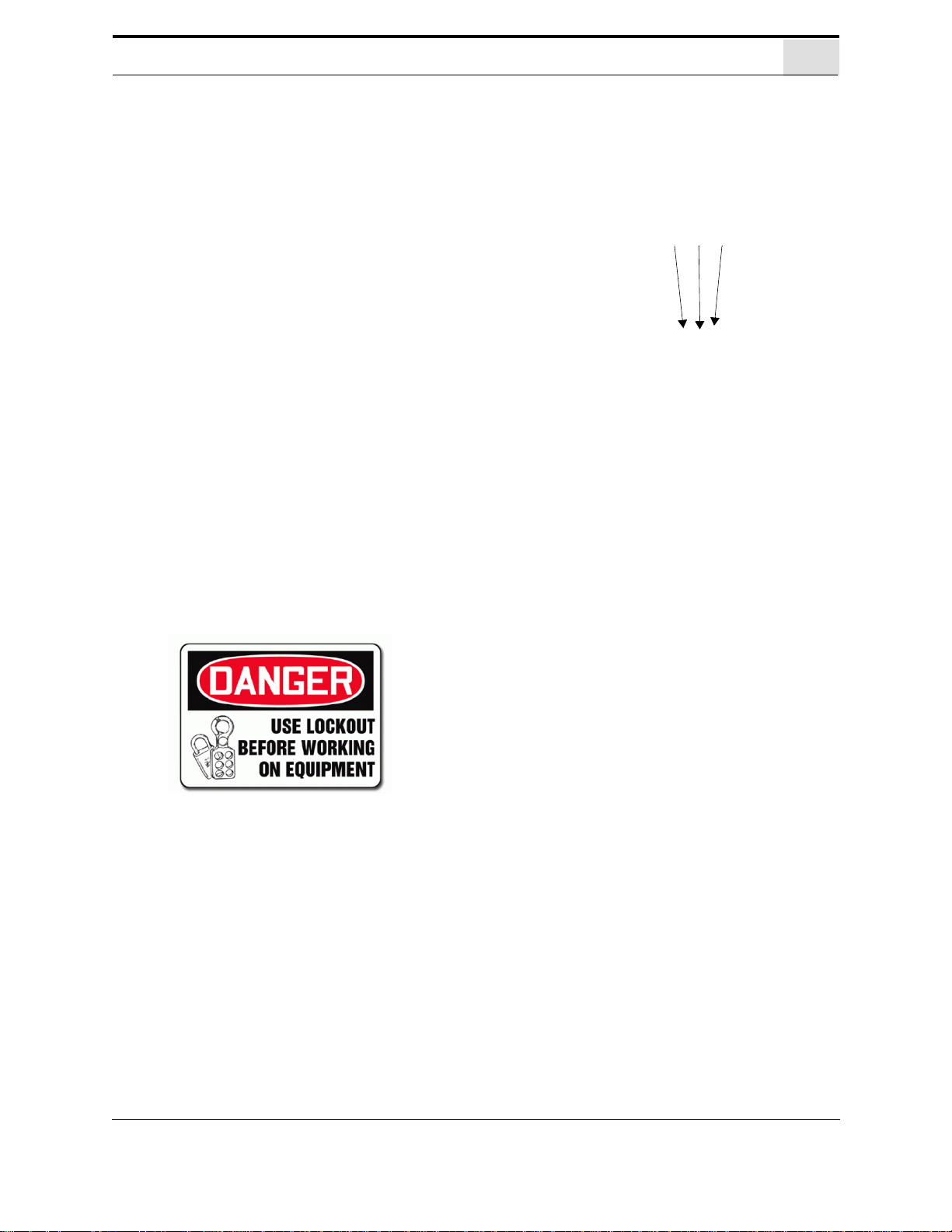
Lockout-Tagout Guidelines
Lockout-Tagout Guidelines
• Place a tag on all padlocks. On the tag, each
operator must put their own name and date.
(These locks are only to be removed by the
person who signs the tag)
• If more than one person is working on the
machine, each additional person places a lock
and tag on each disconnect.
• Only each operator may remove their own
lock and tag.
Important: When many people are all working
on the same machine you will need a multiple
lockout device, such as the one shown here.
Follow the P-R-O-P-E-R lockout rule of thumb.
P...... Process shutdown
R ...... Recognize energy type (electrical, pneumatic, mechanical, etc.)
O...... OFF! Shut off all power sources and isolating devices
P...... Place lock and tag
E...... ENERGY: Release stored energy to a zero-energy state
R ...... Recheck controls and test to ensure they are in the “OFF” state
KVAL Handler Operation/Service Manual
1-8

Lockout Tagout Procedure
1. Evaluate the equipment to fully understand all energy sources (multiple electrical
supplies, air supply and pressure, spring tension, weight shifts, etc.).
2. Inform all affected personnel of the eminent shutdown, and the duration of the
shutdown.
3. Obtain locks, keys, and tags from your employer’s lockout center.
4. Turn off machine. See Chapter 2 for power down and power up procedures.
5. Turn the disconnect switches on ALL electrical and frequency panels to the OFF
position. Then push the red tab to pop it out. Place a padlock through the hole.
Place your tag on the padlock, as per the tagout guidelines below. (see illustration
below).
Power
Note: When multiple people are working on the machine, each person needs to
have a lock on the handle in the extra holes provided.
Insert Lock into hole.
T urn Switch to the
OFF position
Lock and Tag out
This policy is required by OSHA regulation 1910.147 and Cal OSHA’S
SB198 ruling of July 1991.
Use the following lockout procedure to secure this machine while it is
powered down. During a lockout, you disconnect all power and shut
off the air supply. Be sure to use the tagout guidelines noted below.
Pre-Steps Before Lockout Tagout
Lockout Tagout Procedure
Lockout Tagout Power
KVAL Handler Operation/Service Manual
1-9

Lockout Tagout Procedure
6. Turn all air valves to the OFF position and place a pad-
lock through the hole (see illustration below).
NOTE: Place your tag on the padlock, as per the
tagout guidelines.
Lockout Tagout Air Supply
Start Maintenance
7. Once the locks and tags are in place and all personnel are clear, attempt to operate
the machine to ensure equipment will not operate.
8. Maintenance or repairs may started.
Post Maintenance Steps
9. After maintenance is completed, the person performing the work must ensure all
tools, spare parts, test equipment, etc., are completely removed and that all guards
and safety devices are installed.
10. Before removing the locks and tags, the person who attached them shall inspect the
equipment to ensure that the machine will not be put in an unsafe condition when
re-energized.
11. The lock and tag can now be removed (only by the person(s) who placed them),
and the machine can be re-energized.
12. The tags must be destroyed and the locks and keys returned to the lockout center.
KVAL Handler Operation/Service Manual
1-10

Zero-Energy to Start-Up
Zero-Energy to Start-Up
Starting the equipment properly is just as important as the lockout/tagout guidelines in terms of
safety.
Start-up Guidelines
The following guidelines below should be followed to start the equipment.
Inspect
The equipment must be inspected for proper adjustment before starting equipment.
Clean Up
All materials and debris must be cleaned up. Any combustible materials or old parts
used during repairs must be cleaned up and/or properly disposed of.
Replace Guards
Replace all equipment guards. If part of equipment cannot be properly adjusted after
start-up with guard on, contact the KVAL Service team. See “Getting Help from
KVAL” on page 1-13.
Check Controls
Confirm that all switches are in the “OFF” position. Please be advised that some components of the machine may start automatically when energy is restored.
Remove Locks
Each operator must remove his or her own lock and tag. This will ensure that all operators are in a safe place when the equipment is started.
Perform Visual Checks
If the equipment is too large to see all around it, station personnel around the area and
sound the personnel alarm before starting the equipment. If your operation is more
complex, your company’s comprehensive safety procedure may involve additional
steps. You will need to ask your supervisor about these procedures. The company’s
lockout procedure should be posted at each machine. On larger or long-term maintenance or installation projects, the company’s procedures must be explained to all new
operators and a copy of the company’s procedures should be posted on-site for the
duration of the work.
The Company’s procedures should also include provisions for safely handling shift
changes and changes in operators or new operators.Comprehensive lockout/tagout
may use a gang box or other system to ensure that locks are secure and not removed
without authorization.
KVAL Handler Operation/Service Manual
1-11

Zero-Energy to Start-Up
Remember, lockout/tagout procedures work because you are the only one with the key
to your lock. Proper lockout/tagout can save lives, limbs, and money. Help make your
work environment safe for you and your fellow workers. Be sure to follow the P-R-OP-E-R lockout/tagout procedures, and that those around you do also.
Close the Cage Gate
Verify all cage gates are securely closed. Ensure all safety protocols are in effect.
KVAL Handler Operation/Service Manual
1-12

Getting Help from KVAL
Serial Number
3 phase volts
Electrical Print
Air Print
Getting Help from KVAL
Before you seek help, first try the troubleshooting procedures. Follow the procedures below.
If you are unable to resolve the problem:
1. Locate the machine’s Specification Plate and record the serial number, 3 phase
volts, electrical print number, and air print number.
2. Contact our customer support team:
• In the U.S and Canada, call (800) 553-5825 or fax (707) 762-0485
• Outside the U.S. and Canada, call (707) 762-7367 or fax (707) 762-0485
• Email address is service@kvalinc.com
• Hours:
6:00 AM to 4:00 PM Pacific Standard Time, Monday through Thursday
6:30 AM to 1:30 PM Pacific Standard Time, Friday
On-Line Help
On machines with a Beckhoff® PLC and an internet connection, our service team are able to connect, run, and troubleshoot your machine. Ask about this procedure when calling are service team
Product Return Procedure
If you’ve contacted Kval for help and it is determined that a return is necessary , use the procedure
below to return the machine or part.
Note: Non-Warranty returns are subject to a 15% restocking charge.
Obtain the packing slip and/or invoice numbers of the defective unit, and secure a
1.
purchase order number to cover repair costs in the event the unit is determined to be
out of warranty.
2. Reason for return: Before you return the unit, have someone from your organization
with a technical understanding of the machine and its application include answers to
the following questions:
KVAL Handler Operation/Service Manual
1-13

Getting Help from KVAL
• What is the extent of the failure/reason for return? What are the relevant error messages or error codes?
• How long did it operate?
• Did any other items fail at the same time?
• What was happening when the unit failed (e.g., installing the unit, cycling power,
starting other equipment, etc.)?
• How was the product configured (in detail)?
• Which, if any, cables were modified and how?
• With what equipment is the unit interfaced?
• What was the application?
• What was the system environment (temperature, spacing, contaminants, etc.)?
3. Call Kval customer support for a Return Material Authorization (RMA). When you
call:
• Have the packing slip or invoice numbers available.
• Have the documented reason for return available.
4. Send the merchandise back to Kval.
• Make sure the item(s) you are returning are securely packaged and well protected
from shipping damage
• Include the packing slip or invoice numbers.
• Include the documented reason for return.
• Include the RMA number with the parts package.
KVAL Handler Operation/Service Manual
1-14

How to Download the Service Application
1. To download the application, go
the KVAL website (http://
www.kvalinc.com
)
2. At the KVAL website, select the
Support tab. Follow the instruc-
tions on the Support web page.
3. Click the Download button to
download the application that
allows the KVAL technician to
have access to the operator station.
4. After the download is com-
pleted, double-click the program
icon.
Note: Web browsers have different methods of downloading programs. Below are samples of i.e
Explorer and Google web browsers.
Sample of Google Browser: Located at the
bottom left of the screen.
Sample of i.e Explorer: Located at the bottom of the screen. select the arrow and
choose Save and Run
How to Download the Service Application
On machines with Windows (8.1 / 8 / 7 / Vista / XP) and an internet connection, our service team
are able to connect, run, and troubleshoot your machine by way of the operator station.
Download Application
.
KVAL Handler Operation/Service Manual
1-15
5. A pop-up window is displayed.
Accept the request to run the program.
Note: Security settings may differ from plant to
plant. If issues occur, contact your IT department.
6. The interface of the KVAL Support App will be dis-
played. Enter your name in the Your Name field.
The fields are described below:
Session code: An internal number to track this
machine. It is auto filled.
Allow Remote Control: Program is ready to allow
technicians to access machine computer
Your Name Field: Enter your name. The KVAL tech-
nician will use this field to identify this machine.
Description: Enter machine Serial number and
issue.
Indicator: Green indicates there is a good connec-
tion to the service center. If red, there could be an
issue with a LAN connection. Check the connections
in the plant.
7. After the KVAL Support App is
loaded and completed, call the
KVAL service center(1-800-553-
5825) and have the technician connect to the machine computer.
8. Click the Allow button to give the
KVAL service technician permission to access the operator station.
We are now ready to troubleshoot.
How to Download the Service Application
KVAL Handler Operation/Service Manual
1-16

How to Download the Service Application
Page Intentionally Left Blank
KVAL Handler Operation/Service Manual
1-17

Safety Sign-Off Sheet
Safety Sign-Off Sheet
Machine Model Number:_____________________________
A Note to the Operator
This machine can help you be highly productive only if you understand how to use it properly and
follow the safe operating practices described in this document and the machine’s manual. If you
do not understand the machine’s proper operation or ignore the safe operating practices, this
machine can hurt or kill you. It’s in your best interest to safely and properly operate this machine.
Personnel Safety Concerns:
• I have been properly trained in the operation of this machine.
• I will always wear ear protection when operating this machine.
• I will always wear eye protection when operating this machine.
• I will never wear loose clothing or gloves when operating this machine.
• I will watch out for other people. Make sure everyone is clear of this machine
before operation.
• I will always follow my company’s safety procedures. I have read and understand
these guidelines.
Machine Safety Concerns:
• I have been given a tour of the machine and understand all the safety labels, E-
Stops and the actions to take in case of an emergency.
• I will make sure all guards are in place before operation
• I will turn off the compressed air, before loading hardware (staples, screws, etc)
• I will turn off the electrical power, for setup
• If the machine should operate in an unexpected manner stop production I will
immediately and notify a manager, a supervisor, or a qualified service technician.
I have read and understand this document and agree to operate this machine in a safe manner as described above.
Employee
Name (print):___________________ Signature: __________________ Date:____/____/____
Supervisor/Safety Officer/Trainer
Name (print):__________________Signature: __________________ Date:____/____/___
Note: It is recommended you make a copy of this sheet for new operators. If a copy is needed, you may
download a PDF at the KVAL website (http://www.kvalinc.com). You may also contact our Service
Department at (800) 553-5825 or email at service@kvalinc.com.
KVAL Handler Operation/Service Manual
1-18

Safety Sign-Off Sheet
KVAL Handler Operation/Service Manual
1-19

CHAPTER 2 Operation of the Handler
This chapter describes components, assemblies, and the user interface of the KVAL Handler
Feeder or Stacker The content is geared to help operators understand the basic operation of the
Handler.
Chapter 2 at a Glance
Section Name Summary Page
Operator’s Tour
Quick Start
Powering Operations for
the Commander III
Description of User
Interface Sc
reens
Descriptions of the operation of the parts and assemblies
machine.
of the
A summary of the steps to machine a door. page 2-12
Descriptions of
emergency stops
An overall description of the user interface.
• Screen Selection Menu Map 2-19
• Main Menu 2-20
• Auto Run Screen 2-21
• Maintenance Feed Thru 2-22
• Machine Data 2-23
• Manual Run Screen 2-24
• Maintenance Carriage Screen 2-24
power up, power down, homing, and
page 2-2
ge 2-13
pa
page 2-15
2-1

Operator’s Tour
Electrical
Panel
Roll Table
Boom
Motor
Up and
Down
Motor
Safety Curtain
Sender
Door Lift
Boom and Grabber
Door Out
Fence
Safety Curtain
Receiver
Door
Stack
Area
Option H: Manual
Door Feed
Clamps
Clamps
Door
Stack
Area
Fence
Staging Area
Control
Feed
Motor
Operator’s Tour
The Handler can be used as a feeder or a stacker. A feeder takes a door from a stack and inputs it
into a door machine for processing. A stacker is located at the end process and takes the door from
the door machine and stacks them to get ready for the next step in manufacturing. This manual
describes the Handler as a feeder.
Handler Top View
FIGURE 2-1. To p View of the Handler
KVAL Handler Operation/Service Manual
2-2

Identification of Assemblies on Handler
Bottom View
Wooden Door Guides
Door Stack Area
Push Over Belts
In Feed Motor:
Drives belt driven
rollers to move door
into the next
machine.
Grabber
Up and Down Motor
In Feed Motor
Safety Curtain
Stops the process if
Stack area is
entered.
Controls
Main Operating Station
Enter Stack Area Control
Pop-up Cylinders:
Pops up to move door
to fence
Boom Motor
ClampsX2
Cylinders
move clamps
Inwards to
clamp the
door.
Outwards to
unclamp
Clamp
Boom Chain
Operator’s Tour
FIGURE 2-2. Door Input Area
KVAL Handler Operation/Service Manual
2-3

Operator’s Tour
The Brake:
Automatically applies braking force when the gripper comes to a stop while grabbing
doors from the stack, and when it raises the gripper (and door) to the top of the carriage.
Prevents the gripper from lowering too far, and/or unexpectedly lowering once raised or
when air pressure to the clutch fails.
Boom Chain: Moves boom
over to door stack for pick up
and back to the rollers for placing the door.
Driven by the Boom Motor
located under the feed table.
The Motor:
Works with Speed Reducer and Brake to
move the grabber up and down to pick up
and place doors.
Speed Reducer
Reduces speed of the Up and Down
Motor when picking up or loading doors.
The Boom: Moves to lower to
pick up doors and move to
place on feed table
Clutch:
.Controls Torque for the weight of the door
About the Up and Down Motor
FIGURE 2-3. About the Up and Down Motor
KVAL Handler Operation/Service Manual
2-4

Operator’s Tour
Handler
Feeder
Controls
CONTROL TRANSFORMER button
START MACHINE button.
STOP Machine button
DISABLE (Pause) Machine button
Operators Station
The operator’s station contains a touch screen to input data and operate the Handler . The location
of station may vary due to customer specifications. Along with the Handler, other interfaces may
also be located in this area.
FIGURE 2-4. Operator Station Example
KVAL Handler Operation/Service Manual
2-5

Operator’s Tour
To Enter Staging Area (Request Access):
1. Push the blue Request Access button out
2. A blue light will blink and the lift will move a door over
the rollers.
3. After the blue light goes solid, it is OK to enter.
4. After completed task, EXIT staging area
5. Pull the blue Request Access button out
6. Press the Blue Reset Light Curtain button to continue
with door processing, after the safety light curtain is broken.
Disable Lift: Press to disable or pause the lift. the lift will hold at
the point of being disabled.
Emergency Stop: Press in Emergency will stop machine. Will
maintain clamp and lift.
Control at Door Staging Area
These controls are normally located at the door placement area. The controls are designed for
safety during the operation of the machine. The controls can pause the machine to allow safe
entry, disable the lift, reset the lift, and apply emergency stop.
About the Safety Curtain
The Safety Curtain provides safety for personnel who enter the defined area when the machine is
active. If any part of an operator’s body is detected in the defined area, the machine stops the
operation.The machine must be reset from the operators station to continue machining.
The Safety Curtain is composed of an EZ-Screen emitter and receiver. The emitter has a row of
synchronized light-emitting diodes (LEDs) that send signals to the receiver. The receivers have a
a matching row of synchronized photo detectors that read the signal from the emitter. When the
signal is blocked of any beam, the machine stops. To continue machining push the Start button
If the beam is broken, ensure stacking area is clear and press the Reset Light Curtain button
Important: The EZ-Screen system is aligned at the factory. Do not move the emitter or
receiver modules. This may cause misalignment, if the system is misaligned the machine will not start
located on the control at the staging area. See “Control at Door Staging Area” on page 2-6.
KVAL Handler Operation/Service Manual
2-6

Emitter
Receiver
Emitter
Receiver
Machine in operation
Breaking of any beam
stops the machine
Operator’s Tour
FIGURE 2-5. Operation of Safety Curtain
KVAL Handler Operation/Service Manual
2-7

Operator’s Tour
The Photo Electronic Detector uses light as a trigger.
• Photo Eye Detectors contain both emitter and receiver.If an
object is within the Photo Eye’ s sensing field light from the emitter
is reflected from the object back to the receiver. With no object is
in front of the Photo Eye a constant 24VDC is sent to the PLC. If
an object is sensed by the Photo Eye, 0VDC is sent to the PLC.
• As a result, any of the photo detectors output equals 0VDC when a
door is sensed.
• Some detectors have an emitter and receiver built in one unit, such
as an in-feed sensor where a door blocks the light and reflects back
to the unit.
• Some detectors have an emitter and receiver built in separate units, such as the
through beam sensor set at a distance from each other. If an assembly is in between
the two sensors the machine will not operate.
One Package
The Proximity Sensor detects metallic objects without touching them.
• An inductive proximity sensor consists of a coil and ferrite core
arrangement, an oscillator and detector circuit, and a solid-state
output. The ferrite core and oscillator create a field generating out
the front of the sensor. When a metal object enters the field, a loss in amplitude
occurs. The detector circuit recognizes the loss of amplitude and generates 0VDC
to send to the PLC. When the metal object leaves the sensing area, the sensor to
returns to 24VDC and sends it to the PLC.
• As a result, if a metal object is sensed, the output of the sensor equals 0VDC
The Limit Switch is activated by an assembly moving a switch arm.
• .Depending on the model of limit switch, the
amount of “pre-travel” (amount of movement from
the arms resting position) is either 5 or 20 degrees
before the limit switch actuates (Clicks).
Switch Arm
About Switches and Sensors
On the this machine sensors and limit switches provide input to the PLC as part of the automation
of the door moving process. Inputs can include feed through, door clamping, door location, and
limits of movement of machine assemblies.
Sensors are electronically tripped while limit switches are mechanically tripped. It is important to
keep the sensors cleaned and aligned to keep the door process running smoothly. There are two
classifications of sensors: Photo Electronic and Inductive Proximity Sensor.
.
KVAL Handler Operation/Service Manual
2-8

Operator’s Tour
The Main Electrical Panel:
• Supplies voltages to the machine
• Contains the PLC (Programmable Logic Controller)
• Contains VFD’s (Variable Frequency Drives).
Warning: High Voltage is present in this pan el at the top of the Three Phase
input even with the disconnect off. If working on the panel, follow disconnect
protocol. See “Lockout Tagout Procedure” on page 1-9.
PLC (Handler)
Relays
24V DC Supply
110 VAC
Terminals
24VDC-
Terminals
VFD/ Feeder Motor
Transformer
High Voltage Input
PDR / Disconnect
Contactors and Thermal Over-
load (Up and Down Motor)
Fuses
Hub
About the Electrical Panels
This section is an overview of the electrical components in the Main Electrical Panel. Refer the
machine's electrical prints for in-depth information.
FIGURE 2-6. Feeder Electrical Panel
KVAL Handler Operation/Service Manual
2-9

Operator’s Tour
Control Power –This
light illuminates when
the Control Transformer turned on and
the power is working
on secondary side-of
transformer
Overload Relay –
This circuit is jumped.
It should always light.
E-Stop – The back
gate is closed and Frame E-stop is not activated when this light is on.
24VDC – This light
comes on once the
ACR is latch and the
24VDC power Supply
is working
Stop – This light will
be on if Machine
Stop button is deac-
tivated.
Start – This light will
be on once the
Machine Start button
is pressed and the
ACR Relay is latched.
Description of the Six Light Panel
The six lights on this panel indicate the status of the Handler system.
Note: See “Troubleshooting with the Status Light Panel” on page 5-12., for informa-
tion on using this panel for troubleshooting.
The Sequence that the lights activate is as follows:
1. Control Power
2. Overload Relay
3. E-Stop
4. Stop
5. Start
6. 24VDC
KVAL Handler Operation/Service Manual
2-10

Process to Pick up and Feed a Door
Door
Stack
Area
Door
Stack
Area
T o the Next
Machine
Input Door
Process to Pick up and Feed a Door
1. The Boom moves the Grabber over and down to clamp door
2. The Grabber Picks up a door
3. The Boom moves the door over the Roller Table.
4. The door is placed on the Roller Table
5. The Grabber releases the door and moves up.
6. The Pop up cylinders and the push over belts move the door to the fence
7. The Feed Belt drive rolls door to the next machine
About Option H
The Option H machine allows door to be fed manually from the end of the machine.
Press the Reset Lift Button.
Press the End-Feed Mode button on the Run screen to enter this mode. When active, the boom will
move over the stack area and the input will switch to the end of the machine. Manual fed in doors
will trigger the infeed sensor and move the door to the next machine.
Option H1: Option H1 adds a foot switch to manual to feed door out of the Handler to the next
machine.
KVAL Handler Operation/Service Manual
2-11

Quick Start Feeder
Ensure factory air is present at machine and the Handler main air supply valve is
turned on.
Power up the Handler. See “How to Power Up the Handler” on page 2-13.
Clear the stacking area of clutter. Ensure all personnel are clear of the area. Place
a pallet to stack doors upon
P lace the stack of doors against the wooden stops.
After performing the steps in “How to Power Up the Handler” on page 2-13, select the Run Button from the Main
screen.
Select the Set Counter button.
Enter the number of doors to
be processed by way of the
keypad that is displayed.
Press the ENT button and Pre-
vious Menu
to return to the
Run Screen
d
Select the Auto Feed Button
Select the Reset Lift Button (To Home machine)
Select the Reset Lift Button (To enable Sequence)
Select the Call Door Button to start the Door Feeding
Process.
The Handler will load the quantity of doors in the Stack
Count
box.
Quick Start Feeder
Warning: Never operate the Handler until you are sure that everyone is clear of the machine's
movement area, and the doors "Drop Zone".
KVAL Handler Operation/Service Manual
2-12

Powering the Handler
4. Push the CONTROL TRANSFORMER button in
to the ON position. It should light up.
5. Push the Blue Rest Light Curtain Button,
located at the Handler staging area.
6. Push the green START MACHINE button.
7. All lights on the status light panel on the electrical
box should be illuminated.
This section describe how to power up and to power down the Handler
Powering up the system includes:
• Applying power to the entire system.
• Starting the Control Circuit.
Powering down the system includes:
• Turning off the computer.
• Shutting down the control power.
• Removing power from the entire system.
How to Power Up the Handler
1. Ensure factory air is applied to machine and main air supply is turned on.
2. Check that all E-Stop buttons are out.
3. Make sure the electrical disconnect the electrical cabinet is turned to the ON posi-
tion.
Powering the Handler
.
KVAL Handler Operation/Service Manual
2-13

Powering the Handler
1
2
3
How to Power Down the Handler
1.
Push the STOP Button.
2. Push the CONTROL TRANSFORMER but-
ton in to the OFF position.
3. KV AL also recommends that you turn the
disconnect switch on the electrical cabinet to OFF; this helps reduce possible
damage resulting from power surges
from electrical storms.
Emergency Shutdown and Recovery
Depending on the model of machine, there are emergency shutdown (EStop) switches located at key points around the machine.
The E-Stop switches are to be used when the machine is out of control or is
about to damage personnel or equipment.
When an E-Stop switch is activated, high voltage power is cut to the
machine. The motors will stop but power to the PLC and the Operator Station Screen will remain on.
The Handler will maintain the position of the machine at the time of the Emergency Stop. There
fore if the door is clamped in mid lift, the door will stay at that position.
Note: The machine responds in the same way if you press the STOP button on the
operator's station.
To Resume Normal Operation after an E-Stop
If an E-Stop is activated, use the following procedure to recover , after the cause of the emer gency
stop is resolved:
1. De-activate the E-Stop switch by pulling it out.
2. Push the START MACHINE button on the operator's station
3. Home the Machine.
Pause (Disable and Hold Button)
KVAL Handler Operation/Service Manual
2-14

Description of User Interface Screens
Description of User Interface Screens
This section describes the user interface screen. The user interface allows the operator to use a
touch screen to control the door machining process. Below are the menu selections for the Handler
Screen Selection Menu Map as a Feeder or Stacker
FIGURE 2-7. Handler Menu Map for Feeder and Stacker
KVAL Handler Operation/Service Manual
2-15

Description of User Interface Screens
Software part
Number & Rev
Input and Output Status: Press to display
an active list of input and output indicators.
Use to troubleshoot machine
Run Menu: Press to display the Run Machine Menu
Maintenance: Press to display inputs and
outputs at the carriage and feed locations.
Machine Data Setup: Press to display
number of doors processed and display
controls.
Manual Run: Manually Jog the Feed and the Carriage
Total Doors:
Total number of
doors processed
(not resettable)
Reset Daily:
Reset the daily
count
Daily Total
Doors: Total
number of doors
processed for the
day
Adjust Levels:
Select the arrow to
increase or decrease
Contrast or Color
Brightness
Previous Menu:
Jump back to
Start Screen
Main Menu
The Main Menu supplies buttons to link to all the Handler user screens. Press the buttons to go the
selected user screens.
Machine Data Setup
Press the Machine and Data Setup button to check daily and total doors processed.
KVAL Handler Operation/Service Manual
2-16

Run Menu
Un-Clamp; Release the
clamp mechanism. Boom
will move over to stack and
unclamp
Call Door: In Auto mode starts
the first door out. In Manual
mode calls each door.
Cycle Enabled/Disabled:
This is an indicator that displays if the Handler is in
Auto Feed or Manual Feed
Reset Lift: Starts the first pick
up sequence. Puts the lift into a
safe position.
Feed Auto/Man: Press to toggle between manual feed and
auto feed
Previous Menu: Press to go
to the Main Menu
Tip: Press and hold the
Reset Button to move an in-
process door to the stack.
Set Counter: Press to enter
the number of doors to process.displays a keypad to enter
door quantity
Stack Count: Displays the
Quantity of doors to process.
input byway of the Set Counter
button.
Reset Counter: Press clear
the quantity in the Stack Count
box.
End-Feed Mode (Not Ready/
Ready): Turns Green when
machine is ready to use the
End-Feed Function
End-Feed Mode ON/OFF:
Press to put machine in End
Feed Mode. This will move the
Boom over the stack and allow
feeding a door from the end of
the machine See “About Option
H” on page 2-11.
Option H:
Control of the Handler is done at the Run Screen.
Description of User Interface Screens
KVAL Handler Operation/Service Manual
2-17

Description of User Interface Screens
The indicators on the screens show the area and location of the sensors. As troubleshooting tool, determine if the sensor is acting correctly at it’s point in the process
About the Maintenance Screens
Use this menu to check the operation of the sensors in the machine.With this tool, outputs and inputs
can be viewed in there on and off states. The indicators on the screen show the area and location of the
sensors. As troubleshooting tool, determine if the sensor is acting correctly at it’s point in the process
Note: Refer to the Electrical Drawings for definite information about the electrical
wiring and designation of the sensors.
INPUT INDICATORS Circular displays like these show the status of the controller
inputs.
OUTPUT INDICATORS Square displays like this show the status of the controller outputs.
About the Status Screens
The Status Screens show the status of the inputs and outputs of the PLC. A red color shows a status of inactive a green color shows a status of active. Use the results of the screens and compare to
the electrical drawing of the PLC to troubleshot.
KVAL Handler Operation/Service Manual
2-18

Description of User Interface Screens
KVAL Handler Operation/Service Manual
2-19

Description of User Interface Screens
Jog Carriage:
Press and Hold the
button to move the
carriage in the
desired direction.
(Up, Down, T o S tack
and To Rolls)
Table:
Press and Hold the
Feed Forward but-
ton to move the door
through he machine.
Unclamp
Press and Hold the
Unclamp button to
release the door.
Do not unclamp if
a door is elevated
by the carriage.
The door will fall
to the ground.
Cycle Enabled/Disabled:
This is an indicator that displays if the Handler is in
Auto Feed or Manual Feed
About the Manual Screen (Jog)
The Manual Screen allows the operator to manually move the Feed and Carriage of the machine.
Important: This screen has access to manual control of the machine. The Unclamp button will
unclamp when the carriage is at any position. DO NOT press the Unclamp button if a door is elevated by the carriage, the door will fall to the ground.
KVAL Handler Operation/Service Manual
2-20

Description of User Interface Screens
KVAL Handler Operation/Service Manual
2-21

CHAPTER 3 System IT Administration
This chapter describes the KVAL Handler controller. The controller is an on board computer that
supplies the user interface and controls the operation of the machine. With the controller, KVAL
can remotely help troubleshoot your machine.
Chapter 3 at a Glance
Section Name Summary Page
About the PLC
This chapter describes the basic parts of the operation of
the PLC in the machine. Such as
page 3-2
3-1

About the PLC
PLC
Inputs and
Outputs
Relays
Hub
24 VDC
Supply
About the PLC
This machine uses an IDEC® CPU module as a PLC (Programmable Logic Controller). In addition to the CPU and the chipset, the module also contains internal main memory. The controller
uses WinLDR® automation software to create the PLC and Motion Control method.
Different model type IDEC PLC’s may be used for each machine. The basic two types are the “all
in one” model and the “slim model”. Both types contain the following
• ACPU module
• Power supply (24V)
• Input/Output modules (analog)
• Connections to the user interface
• Some models have Ethernet connections for Intranet interface
KVAL Handler Operation/Service Manual
3-2

About the PLC
KVAL Handler Operation/Service Manual
3-3

CHAPTER 4 Maintenance of Handler
This chapter describes preventative maintenance steps for KVAL Handler . The content is geared to
guide technicians to keep a regular maintenance schedule for your KVAL machine. Keeping your
KVAL machine maintained is an important piece for successful operation of your door production
process.
Chapter 4 at a Glance
Maintenance Schedule
Lubrication
Requirements
This section describes the assemblies to schedule for
maintenance.
• 300 Cycles
• 600 Cycles
• 3,000 Cy
• 12,000 Cycles
• 72,000 Cycles
is section describes the lubrication requirements for
Th
the machine,
cles
including types of lube to use. This section
includes:
• Linear Bearings, Flange Bearing, and Pillow Blocks
• Gear Motor Lubrication Requirements
• Ball Screws
• Description of Air Input System
• Adjusting the Air Line Lubricator
• Priming the Air Line Lubricator
page 4-2
page 4-6
4-1

Maintenance Schedule
Prior to performing any maintenance, repairs, cleaning or when
clearing jammed debris, you must disconnect, tagout, or lockout the
electrical and air pressure systems. This should be done in accordance with applicable state and/or federal code requirements
To view a video of the maintenance process, visit the KVAL website. Select
the Video Tab to view videos.
http://www.kvalinc.com/
Maintenance Schedule
KVAL recommends the following maintenance schedule to ensure that the machine operates
properly. Cycles refers to the quantity of processed doors. Cleaning curtails build up of sawdust
and grime which causes issues with the operation of the machine. Inspecting, finds issues before
they become problems. Lubricating decreases wear and keeps this machine running smoothly.
Refer to sections following these tables for further description of the maintenance steps.
Note: The steps in the tables below are designed to perform maintenance on a produc-
tion line. Some of the steps may not pertain to all machines.
300 Cycles
Clean Use pressured air to blow off dust and debris on entire machine
Clean Blowoutdustcollectioncans
600 Cycles
Inspect Air Pressure Gages. Adjust, if necessary, to the proper PSI located on the
label. (Adjust only if Trained in Maintenance)
Inspect Inspect Air Filter Water Traps. Empty if necessary
Inspect Inspect the Tooling for wear, (Drill Bits, Cutting Tools, Screw Driver Bits)
Lubricate Lubricate the inside of the Hoppers with a light coat of dry silicone
Clean Empty All Dust Collection Units
spray.(990 Series Specific)
KVAL Handler Operation/Service Manual
4-2

Maintenance Schedule
3,000 Cycles
Inspect Inspect feed belts for proper tension or damage.
Inspect Inspect screw drop tubes for kinks, cracks or wear from rubbing. Ensure tube
clamps are tight.(990 Series Specific)
Inspect Inspect all photo eyes secure and tight.
Inspect Inspectalllimitswitcharmsfortightnessorbreaks
Inspect Inspect split shells and screw receivers on six shooters for cracks or breaks.
Replace if broken.(990 Series Specific)
Inspect Inspect all airlines for kinks or rubbing.
Lubricate Refill all lubricators. Replace fluid if milky or discolored. Use ab ISO 32 stan-
dard hydraulic oil (KVAL PN:SYS-LUBEG).
Lubricate Grease ball screw bearings (if applicable).
Clean Clean all bearing shafts with clean, dry cloth.
12,000 Cycles
Inspect Inspect chains for proper tension or damage
Inspect Inspect all air cylinders for air leaks. Replace if seal is leaking
Inspect Inspecthydrauliclinesforloosefittings,leaksandcracks.
Inspect Inspectballrailshaftsforpittingorabrasions.
Lubricate Cleanandlubricateallslidesandcylinderrodswithdrysiliconespray
Lubricate Lubricateallbearingshaftswithsiliconeandcleanrag.
Clean
Clean inside hopper with WD-40 and a 3M Scotchbrite® pad. Wipe dry with a
clean dry rag.(990 Series Specific)
72,000 Cycles
Inspect Inspect all nuts and bolts for tightnesses Tighten is necessary.
Inspect Checkthatthereisasmoothtransitionwithadoorfeedingintoandoutof
machine.
Back-up Backupcomputersoftware.
Clean Washfilterandlubricatorbowlswithsoapywater.
KVAL Handler Operation/Service Manual
4-3

Maintenance NO-GOES
Maintenance NO-GOES
Do not perform the following. This machine is tuned an calibrated at the factory. If any of these
conditions are changed, timing, accuracy, or damage may occur during the machine process.
• Do not adjust air PSI above or below factory settings
• Do not adjust any and all flow controls from factory settings
• Do not remove shim stock
KVAL Handler Operation/Service Manual
4-4

Lubrication Schedule
Lubrication Schedule
KVAL recommends the following lubrication schedule to ensure that the machine operates properly.
TABLE 4-2. Recommended Lubrication Schedule
Type of Assembly Recommended Schedule Recommended Lubrication Type
Linear Bearing
Every 250 Hours of Machine Operation Dura-Lith Grease (KV
Flange Block Bearing
Ball Screw Every 80 Hours of Machine Operation
Air Line Lubricator One drop of oil every 2 or 3 cycles
Check the lines every week to two weeks
Gear Box 2000 Hours of Machine Operation or six months
ation
of oper
AL P/N L
Either lubricant listed below
to use.
• KVAL P/N SYSLUBG
• Chevron AW Hydraulic Oil 32
• G-C lubricants light AW R&O
• Mobile DTE 24
• Shell Tellus32
• Gulf Harmony 32
• AGMA #8 gear lube
• MOBILUBE HD 80 W-90
• or equivalent
ube EP-2)Pillow Block Bearing
is approved
KVAL Handler Operation/Service Manual
4-5

Lubrication Requirements
Zerk Fittings
Zerk Fitting Location
Depends on Position of
Slide
Lubrication Requirements
This section describes the parts of the machine that require periodic lubrication, and specifies the
lubricants. In addition, it explains how to maintain the lubrication s on the machine.
Linear Bearings, Flange Bearing, and Pillow Blocks
If the bearing is equipped with a grease fitting (Zerk Fitting), it should receive 1 Gram (one pump
from grease gun) of Dura-Lith Grease (KVAL P/N Lube EP-2) every 250 hours of operation.
Note: Bearings without grease fittings have been pre-lubricated at the factory and do
not require further lubrication.
FIGURE 4-8. Zerk Fittings
KVAL Handler Operation/Service Manual
4-6

Lubrication Requirements
Ball screw lubrication points.
Ball Nut
Ball Screw
End
Bearing
End
Bearing
Shop
Air
Input
Air On-
Off Knob
Muffler
Filter
(purge)
Pressure Gauge with adjust Clean Dry Air (CDA) to
Air Blow Off
Lubricator
Lubricated
Air Output
Gear Motor Lubrication Requirements
Oil change is recommended after 2000 operation hours of operation. Use AGMA #8 gear lube or
MOBILUBE HD 80 W-90 or equivalent.
Ball Screws
All ball screws should be lubricated Dura-Lith Grease (KVAL P/N Lube EP-2) for every 80 hours
of operation. At each lubrication grease should be pumped into the fitting until clean grease
comes out around the ball screw.
FIGURE 4-9. Example of a Typical Ball Screw
Important: Make sure to clean excess grease to avoid contact with feed belts, clamping areas, or
the door.
Description of Air Input
The air input takes in shop air and supplies clean dry air (CDA) and lubricated air to the machine.
The clean dry air is diverted to blow off nozzles. The lubricator, located after the CDA filters,
delivers the lubricated air to valve banks and air cylinders.
FIGURE 4-10. Typical Air Line Filter and Lubrication
KVAL Handler Operation/Service Manual
4-7

Lubrication Requirements
(Sight Glass). When the oiler has run dry,
open the knob all the way until flow begins.
Once you have a steady flow, tighten knob
back down until you have one drop per
every other cycle.
Drop will form at end of cane shaped tube
visible inside glass.
Top of Lubricator
Adjusting the Air Line Lubricator
Using the knob on the top of the lubricator, adjust until one drop per every other cycle is used (as
observed through sight glass.)
Priming the Air Line Lubricator
New and used machinery run out of oil from time to time. It is a good practice to check your
machine lubricator to insure that it is putting the proper dose of oil in the air lines. Usually 1 drop
of oil every other cycle is a good rule of thumb. The approved list of oil for lubricators is as follows:
• KVAL P/N SYSLUBG
• Chevron AW Hydraulic Oil 32
• G-C lubricants light AW R&O
• Mobile DTE 24
• Shell Tellus32
• Gulf Harmony 32
To prime the lubricator, find an air line on the carriage section of the machine that is energized,
and disconnect it, allowing the air stream to bleed air pressure away from any persons. Direct the
air stream at the machine so you can see when there is an oily film blowing out of the air hose.
Repeat this same procedure for the back section and other trouble areas.
It is recommended to check the lines every week to two weeks.
KVAL Handler Operation/Service Manual
4-8

Lubrication Requirements
KVAL Handler Operation/Service Manual
4-9

CHAPTER 5 T roubleshooting the Handler
Refer to the Air and Electrical drawings provided with delivery of the
machine. The drawings are normally located in the Electrical Panel. If
copies are unavailable, contact the KVAL Service Department. Have
drawings numbers, model number, and serial number of machine readily available.
Note:
This chapter describes troubleshooting steps to help technicians solve issues that may occur with
your KVAL machine. If help is needed, call or contact our KVAL Service team at (800) 553-5825
or http://www.kvalinc.com.
Chapter 5 at a Glance
Section Name Summary Page
About Motion Control
Troubleshooting Basics
About Contactor Control
About VFD Control
About Pneumatic Control
Using Sensors to Trouble Shoot
Troubleshooting Electrical
Problems
This section contains basic information on the
operation
grams of the control circuits.
This section includes basic troublesho
mation. Includes analyzing sub s to designate a
starting point for troubles
Describes a typical contactor control circuit. page 5-7
Describes a typical VFD circuit. page 5-9
Describes the typical pneumatic circuit. page 5-12
Includes procedure to trouble shoot air cylinders,
such
Includes voltages in the e
Status Light panel to troubleshoot, and VFD troubleshooting.
of motion control circuits. Includes dia-
oting infor-
hooting.
adjusting extension and retraction speed.
as
lectrical pane
ls, using the
page 5-2
page 5-4
page 5-18
page 5-19
KVAL Handler Operation/Service Manual
5-1

About Motion Control
About Motion Control
This section describes the positioning systems found in KVAL machinery. There are three basic
types of motion control methods used in KVAL Machinery.
Sequencing:
Sequencing is a series of events executed in a predetermined order. Most KVAL machines use a
form of sequential motion control. A typical series of events for a KVAL machine are:
1. Move the door into position.
2. Clamp the door.
3. Make the cuts.
4. Unclamp the door.
5. Move the door out.
6. Wait for the next door.
Point to Point:
Point to point motion control involves moving a load from one fixed position to another fixed
position at a constant speed and along one line (axis X,Y, or Z). A typical point to point would be
a drill with a fixed-depth. The drill is either retracted or extended using a pneumatic cylinder.
Typically the drill’s’ travel is limited by physical stops.
Incremental:
Incremental motion control is used when the load is required to be moved with high accuracy to
multiple locations, sometimes in multiple directions (axes). A typical KVAL usage for this system
is a computer controlled router in a door light machine where there is great variety in the cut size,
shape and location.
Basic Control Circuit
This section describes a basic control circuit. The Figure below shows a block diagram of a common control circuit. There are four parts to a motion control system:
KVAL Handler Operation/Service Manual
5-2

Load
User Interface
Force
Positioning
System
Translated
Positioning
Controller
Instructions
Positioning
Instructions
(Optional)
Position Feedback
(Optional)
Machine’s Other
Subsystems
OK to move
Complete
Process
FIGURE 5- 11. Block Diagram of Basic Motion Control
The User Interface:
• Allows communication between the humans and the machine.
Examples: A touch screen, a PC or a button panel.
The Controller:
• Translates entered information into a form the positioning system can understand.
• Listens to the machine’s other subsystems waiting for the OK to move command.
• Sends the positioning instructions to the positioning system.
• Listens to the positioning system for position status (if there is a feedback loop).
• Tells the machine’s other subsystems when the move process is completed.
Examples: A PLC or a dedicated motion control board.
Positioning System:
• Moves the load.
Examples: A motor or a pneumatic cylinder.
The Position Feedback.
• Provides location information to the controller.
Examples: A limit switch, a photo eye, or ferrous eye, a resolver or an encoder
About Motion Control
KVAL Handler Operation/Service Manual
5-3

Troubleshooting Basics
Troubleshooting Basics
Good trouble shooting starts with looking at the whole machine, where every part is suspect. Then
narrowing down the view to the bad part.
Ask: Ask basic questions. For example:
• What was the Machine Trying to Do?
• What Was the Machine Trying to Do Next?
• Was the machine working before?
• Did it happen on first power up or during process?
Narrow: Narrow or determine the sequence and subsystem where the issue occurs. For example:
• Did the issue happen when door was being fed in?
• Is the router not cutting?
• Is the cut out of specification?
Note: See Table 5-1 on page 5 for sequence and subsystem information.
Verify: Verify or analyze the subsystem assembly that is responsible for the issue. For example:
• How is the subsystem supposed to work?
• What is keeping the subsystem from working?
Note: See“Analyze the Sub Systems” on page 5-5 for information on verifying and
analyzing subsystems.
Before you Adjust
Sometimes simple problems can seem to be complex issues. Before making adjustments, check
for the following common issues.
1. Is the loaded setup correct for the current cut?
2. Are the stops set up correctly?
3. When did the problem first start?
• At first Start-Up?
• During the Run?
4. When was the last calibration?
5. Is the door true?
6. Use Router Bit Depth Gauge (PN: 432C) to check depth of Bits
7. Check tools for wear.
KVAL Handler Operation/Service Manual
5-4

Before you Adjust
Determine What:
What Subsystem is Responsible for the Failed Sequence
Step.
Analyze the subsystem:
Check the Load.
Check the Position Feed Back.
Check the Positioning System
See “Analyze the Sub Systems” on
page 5-5
TABLE 5-1. Typical KVAL Machine Sequence
Typical Machine Sequence Responsible Subsystem
1. Move Door into Position Feed System
2. Clamp the Door Door Clamp
3. Make the Cuts Cutter Positioning
Cutter Power
4. Unclamp the Door Door Clamp
5. Move Door Out Feed System
6. W ait for Next Door Feed System
Basic Troubleshooting Steps
Determine Where:
The Sequence Step Where
the Failure Occurs
What was the Machine Trying to Do?
What Was the Machine Trying to Do Next?
Check the Sequences in the Table Below.
How is the Broken Section Suppose to Work?
What is Keeping the Broken Section From
Working?
What Part of the Machine is not Working?
Check the Subsystems in the Table Below.
Ask
Narrow
Verify
Troubleshooting Basics
Analyze the Sub Systems
1. Check the Load for mechanical issues
• Is the Load “bound up?
• Is there sufficient lubrication?
• Is it an alignment issue?
• Is anything damaged?
2. Check the Position Feed Back.
KVAL Handler Operation/Service Manual
5-5

Troubleshooting Basics
• Does the Position Feed Back agree with the Load position?
In other words are the correct photo eyes, limit switches or ferrous sensors acti-
vated?
Check the controller inputs to insure the proper sensors are activated. If the control-
ler is a PLC, an activated input is lit. Some touch screens have inputs status also.
3. Common Position Feedback failures:
• Photo Eye:
• Limit Switch: Stuck, or failure
• Wiring: Broken, worn insulation
• PLC: Bad input port
• Bad Output: Relay may be stuck
• Air Solenoid Valve: May be stuck or not working.
4. Check the Positioning System
a) Bad element or bad cable
b) Eyes not set to correct height
c) Lighting from ceiling may be interfering with sensor
Follow the circuit from the Controller output to the Load and check for component failures.
KVAL Handler Operation/Service Manual
5-6

About a Typical Contactor Control
High Voltage may cause personnel injury or death. Troubleshooting checks
must be performed by a Qualified Electrical Technician.
PLC
Output
Fuse(s)
Line
Vol ta g e
(Power)
Contactor
Control
(Coil)
Input
Power
Input
Power
Output
Control Circuit
Common
ON
Should measure
Control Voltage
120 VAC here
Should measure
Line Voltage here
Should measure
Line Voltage here
Line Voltage here
Should measure
Relay
120 VAC
DC -
Should measure
24 VDC here
Control Voltage
Motor
ON
Thermal
OverLoad
RESET
#2
#2
Pre 2006 Machines do not have this Relay.
Measure 120 VAC at the Control Coil
Schematic Drawing of Contactor and Thermal Overload
Note: Pre-2006
machines may
not contain the
24 Volt relay.
120 Vac is
directly fed into
the Control Coil.
Check the input
circuitry to the
Control Coil for
120 Vac.
About a Typical Contactor Control
Unlike general-purpose relays, contactors are designed to be directly connected to high-current
load devices. Contactors are designed to control and suppress the arc produced when interrupting
heavy motor currents.The figure below shows a block diagram of a typical contactor circuit with
typical voltages.Thermal overload relays are commonly attached to the contactor. They offer protection for motors in the event of overload or phase failure. A Reset button is included to clear an
error in the relay.
KVAL Handler Operation/Service Manual
FIGURE 5- 12. Block Diagram of a Common Contactor Circuit
5-7

Contactor
Thermal
Overload
About a Typical Contactor Control
FIGURE 5- 13. Contactor Bank
About Contactor Troubleshooting
The Thermal Overload Circuit opens the motor circuit when current draw causes the motor to run
too hot. The overload limits are set at the factory, do not adjust the limits.
The overloads are normally in series, therefore if one trips, all on that circuit stop working.
Use the Six Light panel as a trigger to check the circuit. See “Troubleshooting with the Status
Light Panel” on page 5-21 .
1. Open the Main Electrical Cabinet to find the Contactor /Thermal Overload Assem-
bly
2. Press each ‘Green” Reset button on the Thermal Overload. An audible click will be
heard on the tripped circuit. (Take note of tripped circuit.)
3. Once the overloads are reset, verify LED’s are on.
4. Rerun the machine and verify that motor runs without tripping the circuit.
5. If the same overload keeps tripping, verify condition.
6. Follow circuit path using the E-Drawing as a reference.
a.Common issues: Check for bad wire, bad motor, or if load is too great for cur-
rent draw.
KVAL Handler Operation/Service Manual
5-8

About Typical VFD Motor Drive Control
High Voltage may cause personnel injury or death. Troubleshooting checks
must be performed by a Qualified Electrical Technician.
Common Motor Drive Control:
PLC
Output
Fuse(s)
Line
Voltage
Motor
(Power)
Motor
Power
Input
Output
Power
Control Circuit
Common
ON
Measure
Control Voltage
-24 VDC here
Measure
Line Voltage here
Measure
Line Voltage here
ON
Drive
STF (Forward)
RL
STR (Revers 2)
SD (COMMON)
OFF
OFF
OFF
Run
300
Run Light
should be ON
Displays the
Motor Frequency
15 to 300 Mhz
Schematic Drawing of VFD
Note: The output to
motor “C” contains
pulse signals at
varying frequencies.
A DMM may not be
able to measure the
frequency and the
pulse rate.
Use the VFD interface to check, current, voltage and
frequency.
About Typical VFD Motor Drive Control
An adjustable-speed drive is used to control the motor speed and torque by varying motor input
frequency and voltage. A variable-frequency drive (VFD) is used in KVAL machinery to accurately drive motors for machining or moving product through the machine. The figure below
shows a block diagram of a typical motor drive circuit.
FIGURE 5- 14. Block Diagram of a Common Drive Control
KVAL Handler Operation/Service Manual
5-9

About Typical VFD Motor Drive Control
VFD models vary in KVAL machines depending on where it is used, voltage requirements and
type of PLC used. This is a general view on the VFD. See the machine’s Electrical Print for
detailed information.
Line Voltage IN
Converted Signal OUT to Motor
Operation Panel: Access to
manual operation VFD. This
panel can be used for troubleshooting purposes. Fault
Errors will be displayed if any
occur.
During normal operation the
Run LED is lit or flickers and
the frequency of the motor is
displayed.
Control Circuit Board: Contains connections to PLC and
other control circuits.
Includes:
• Control input signals
• Speed Functions
• Relay Outputs
• Jumpers
• Output to reset switch
About the VFD
A VFD (Variable Frequency Drive) takes the raw input from the 3 phase line voltage and converts
it by varying the frequency and voltage of the input voltage. Changes in the output voltage varies
speed and force of the motor. For example: A lower frequency will result in a slower speed.
The VFD converts the voltage but is “told what to do” by the PLC (Programical Logic Controller). The output voltage is then sent to the motor . For a block diagram, see Figure 5- 14 on page 5-
9
.
FIGURE 5- 15. Sample of VFD
KVAL Handler Operation/Service Manual
5-10

About VFD Troubleshooting
VFD Reset
Buttons
This section describes some troubleshooting tools for the VFDs.
Error Checking on the Variable Frequency Drives
VFDs (Variable Frequency Drives) interact with hinge and faceplate routers, width
adjust motors, and feed motors. If issues occur, error codes are displayed on the VFDs.
To help troubleshoot, refer to the VFD manuals located in the High Frequency Panel
for lists of the error codes.
Using the Reset Buttons
In some rare occasions an electrical spike may cause a VFD to shut down. The reset
buttons are located on the door of the VFD panels. The button contains the VFD function printed on the button. If a VFD is tripped to “OFF” the button will be lit. To reset
a VFD:
1. Push lighted button to reset the indicated motor
b.If the button light turns off, continue with production.
c.If the button stays lit:
• identify the motor by way of the label on the button.
About Typical VFD Motor Drive Control
• turn off that function at the switch panel. Check the corresponding output
on the PLC output. If the output is on it will not let the motor reset. Disconnect the output wire and verify that the motor circuit is not causing
the issue.
d.If issue continues, read error code on the VFD* display and look up the error
code in the VFD manual. Follow the instructions in the VFD manual. If issues
continue, contact our Service Center.
FIGURE 5- 16. VFD Reset Buttons
Note: The number of reset buttons depends on the machine type and option. The fig-
ure above shows a machine with 11 VFDs
*
The VFD manuals are located in the Electrical Panels. On some machines, documentation can be found in the operation station in the documen-
tation folder.
KVAL Handler Operation/Service Manual
5-11

About a Typical Pneumatic Circuit
PLC
Output
High
Pressure
Air
Cylinder
Common
Control Circuit
ON
Measure
24 VDC here
Control Voltage
Should have High
Pressure air here
Cylinder
Control
Control
(Coil)
Input
Air
Input
Air
Output
Val ve
Should have High
Pressure air on
Activated Output
Schematic Drawing of Pneumatic Circuit
Note: Pre-2006
machines may
not contain the
24 Volt relay.
120 Vac is
directly fed into
the Control Coil.
Check the input
circuitry to the
Control Coil for
120 Vac.
Note: In this
sample set-up,
Port A is normally open and
Port B is normally closed. If
power is OFF,
air should be on
Port B.
About a Typical Pneumatic Circuit
A control valve (solenoid) is used to drive cylinders to move different loads in the machine. The
solenoid if controlled by the PLC by applying a high voltage or a low voltage to a control coil.
Controls for example are: extending and retracting router, drill, clamping a door.
KVAL Handler Operation/Service Manual
FIGURE 5- 17. Block Diagram of a Pneumatic Circuit
5-12

About a Typical Pneumatic Circuit
Air Input
Cylinder
Retract
Cylinder
Extend
Electrical Wiring Box:
Contains inputs from PLC
to Coils (Solenoids)
Manifold: Base to accept air
input and output air.
Coil (Solenoid): Receives
input(24V) from PLC to open a port
Solenoid type will vary with machine application.
Common controls include an operational LED and
Manual operation button
Manual Activate Button: Push to toggle solenoid to the
‘ON’ state. activates if power is off.
Indicator: a Lit LED indicates the solenoid is in
use.Red LED= the ‘A’ Port on a single valve. If double
valve, Red LED= the ‘A’ Port and Green LED = the ‘B’
port.
Typical Pneumatic Assembly
Pneumatic assembly setups vary in KVAL machines depending on where it is used and air
requirements.This is a general overview of a pneumatic assembly. See the machine’s Air
Print for detailed information.
FIGURE 5- 18. Typical Pneumatic Assembly
About the Coil (Solenoid)
The Solenoids are connected to the top of the manifold. Labels indicating their function and PLC
connections are attached to the solenoid body. Use this information to troubleshoot system if necessary.
FIGURE 5- 19. Solenoids in Manifold
KVAL Handler Operation/Service Manual
5-13

About a Typical Pneumatic Circuit
Retract Motion
Extend Motion
Air
Air
1. PLC drives Control Valve.
2. Valve delivers compressed
air to the cylinder.
3. Cylinder piston rod is
extended when air is
delivered to port “A”
4.
Cylinder piston rod is
retracted when air is
delivered to port “B”
About Cylinder Operation
To see a block diagram of general pneumatic connections, see Figure 5- 17 on page 5-12. The figure below, shows a cross-section of a cylinder in action.
FIGURE 5- 20. Cross-section of Air Cylinder
How the Pneumatic System Works
The Pneumatic system consists of a brain (PLC), an action (Positioning System), and a result
(Moving the Load). For a generalized representative, this section describes the process to
move a router to the extend and the retract position with a double valve.
Extend Process
If PLC determines the conditions are right to extend the Router:
1. The PLC applies the control voltage to the Control Valve which directs com-
pressed air to extend port of the Cylinder.
2. The Cylinder and Router are extended deactivating the Retract Sensor
The Router fully extends activating the Extend Sensor.
3.
KVAL Handler Operation/Service Manual
5-14

About a Typical Pneumatic Circuit
Positioning
System
Load
Force
Translated
Positioning
PLC
Instructions
Position Feedback
Extend Sensor:
Retracted Sensor:
Deactivated
Activated
24 Volts
Extended
Cylinder
24 V Applied
Router Assembly (Load)
Position Feed Back
Air In
Control Valve
Extend
Sensor
Activated
Air Pressure Extends
Cylinder and Router
Assembly
EXTENDED
4. The PLC senses the voltage from the Extend Sensor and removes the control voltage
to the Control Valve.
Retract Process
If the PLC determines the conditions are right to retract the Router:
1. The Control Valve directs compressed air to the retract port of the Cylinder.
The Cylinder and Router retract deactivating the Extend Sensor
2.
When the Cylinder and Router are fully retracted, the Retract Sensor is activated.
3.
4. The PLC senses the voltage from the Retract Sensor completing the process
KVAL Handler Operation/Service Manual
5-15

Cylinder
0 V
Router Assembly (Load)
Position Feed Back
Air In
Control Valve
Retract
Sensor
Activated
Air Pressure Retracts
Cylinder and Router
Assembly
RETRACTED
Positioning
System
Load
Force
Translated
Positioning
PLC
Instructions
Position Feedback
Extended Sensor:
Retracted Sensor:
Activated
Deactivated
0 Volts
Retracted
About a Typical Pneumatic Circuit
Important Notice about Adjusting Cylinder Speed
Do not adjust the cylinders to speed up production. The air cylinder timing is part of a well
tuned system of electronics, programming, and mechanics. Adjustment of the cylinders for speed
can cause unsatisfactory results, in-feed and out-feed problems, far marks in the corners of hinge
pockets, and flipping screws in Hoppers.
However, sometimes machine settling, mechanics be “broken in” may be cause to slightly adjust
extend and retraction speed.
If more than 1/2 turn on adjustment knobs are needed, call in a specialist or check with
KVAL customer service at 1-800-553-5825.
KVAL Handler Operation/Service Manual
5-16

Adjusting Cylinder Extend Speed
:
Adjusting Cylinder Retraction Speed
About a Typical Pneumatic Circuit
Tip: If Installing a new flow control assembly, shut down the flow control and back
out 4 to 5 turns. this position is a good starting point for kine adjust.
KVAL Handler Operation/Service Manual
5-17

Using Sensors to Trouble Shoot
Using Sensors to Trouble Shoot
• Photo Sensors often get dirty. Make sure they are clean. If they are not clean, d ebris
may block the signal or provide a false signal.
• Check output voltages of the sensors in the active mode. The voltage should effectively equal 0 VDC
• Check the output voltages of the sensors in inactive mode.The voltage should effec-
tively equal 24 VDC
• The distance from an eye to the door should be in range. T y pically the range should
be 3/4'' to 7/8'' from the top of all eyes to the door.
.
KVAL Handler Operation/Service Manual
5-18

Troubleshooting Electrical Problems
Refer to Air and Electrical Schematics provided with delivery of the
machine. Schematics are located in the Electrical Panel. If copies
are unavailable, contact the KVAL Service Department. Have
model number and serial number of machine readily available.
NOTE:
The following checks require the electrical panel to be
energized. These troubleshooting checks must be performed by a Qualified Electrical Technician.
Troubleshooting Electrical Problems
The electrical component systems are designed to expedite the troubleshooting process and minimize “down time”. In general, component systems have the input or feed functions at the top.
Output or load functions are positioned at the bottom. Most two-voltage electrical panels are
designed with the LOW VOLTAGES on the LEFT, and the HIGH VOLTAGES on the RIGHT.
The majority of the system components are labeled with numbers that correspond with the electrical prints included in the electrical box door.
Computer controlled machines have signals on the computer that light up when the input or output functions are energized, respectively. Computer controlled as well as non-computer controlled
machines have white 120V control power terminal strips. This will indicate power supply from
the respective circuits.
PLC controllers also have lights on them for the input and output functions. You can easily find
out which circuits are failing by watching the lights turn on or off. Compare the lights on the
IDEC or Beckhoff controllers to the electrical print to determine what systems are being affected.
If the Power Stops During Normal Operation
1. Check that the input power disconnect switch is not turned off.
2. Check that all of the emergency stop buttons are in the normal position.
3. Check the Six Lights on the Electrical Panel. See “Troubleshooting with the Status
Light Panel” on page 5-21.
Lockout and Tagout the main power source.
1. Turn the panel disconnect switch in the off position, open the electrical panel door.
2. Observe the disconnect switches. Look for loose or broken wires at the disconnect
then at all of the components.
3. Check for continuity of all fuses with an OHM meter. (Fuses need to be removed
from the bottom side of the fuse holder before measuring the fuses)
KVAL Handler Operation/Service Manual
5-19

4. W ith the power of f, check for motor overloads by pressing each reset button (usu-
ally at the bottom of the panel) in SEQUENCE. If one is tripped there will be a
slight resistance to touch and a “click” sound as it is reset.
Trip Indicator
Press Reset
Thermal Overload Relay
Test
Troubleshooting Electrical Problems
Check for Tripped Circuits
1. Remove lock and tag outs on the main power sources.
2. Manually close disconnect sensors and energize the control circuit or transformer
with its respective sensor. Check the Status Light Panel,. If all lights are observed,
there are no overloads or emergency stops tripped.
Note: Most electrical problems are related to mechanical malfunction (e.g., stuck
motors, jammed chain, blocked photo sensors etc.)
Note: If a solenoid valve is suspected, and not cleared in the air checks section, it can
be electrically jumped to check operation.
KVAL Handler Operation/Service Manual
5-20

Troubleshooting with the Status Light Panel
The sequence that the lights turn on are
as follows:
1. Control Power (Amber)
2. Overload Relay (Amber)
3. E-Stop (Amber)
4. Stop (Amber)
5. Start (Amber)
6. 24VDC (Green)
Troubleshooting with the Status Light Panel
The Status Light Panel is located on the Electrical Panel. All six lights are illuminated when the
system is in proper working order. The lights turn on in a sequence and will stop at the point
where a fault is first detected.
If one or more lights are OFF, follow the process below to isolate the cause.
NOTE: Be sure to proceed down the table, starting with the CONTROL POWER light.
STEP 1:Control Power (Amber). If light is OFF go to item A on page 5-22.
STEP 2:Overload Relay (Amber) If light is OFF go to item B on page 5-23.
STEP 3:E-Stop (Amber) If light is OFF go to item C on page 5-23.
STEP 4: Stop (Amber) If light is OFF go to item D on page 5-23.
STEP 5: Start (Amber) If light is OFF go to item E on page 5-24.
STEP 6: 24VDC (Green light is OFF go to item F on page 5-24.
KVAL Handler Operation/Service Manual
5-21

1. Check if the Control Transformer button is pulled
out.
4. Is there 120 VAC between #1 & #2 on the 120 VAC Terminal Strip? If not, check
the fuse on the output side of the Control Transformer . If fuse is good, check power
coming out of Control Transformer.
5. If no power on the output side, and there is power going into the top of the Control
Transformer, replace the Control Transformer.
6. If there is power at the Control Transformer, check the wiring of the black and
white wire going from the Control Transformer to the 120 VAC Terminal Strip.
7. If there is no power between #1 and #2, check the secondary side of the trans-
former.
a.Check between X1 and X2. If no power is measured it is a bad transformer.
b.If there is power at X1 and X2, check the other side of the fuse. If now
power, replace the fuse.
2. Is the Disconnect Switch on the main electrical cabinet set to
ON?
Switch
3. Is there 208, 220, 440, or 575 VAC to the top side (input) of the Control Trans-
former? If not, check the fuses at the Fuse Block, and the contacts on the Control
Transformer button on the switch panel.
Input
High Vac
Output
120 Vac
Typical Control Transformer
Control Power Light OFF
Troubleshooting with the Status Light Panel
KVAL Handler Operation/Service Manual
5-22

1. Check Motor Overload Circuits
2. W ith power on, check the trip indicator LED on the
overload. If indicator is orange, press the Reset
Button to reset the overload circuit. Retest the
Machine.
Overload Relay Light OFF
Contactors
Overload
Relays
Reset Button. Factory set on the ''H''
Setting.
Test or Stop
Trip Indicator
Factory Set Current
Rating Adjust
E-Stop Light OFF
Check if any E-Stop buttons are pulled out.
NOTE: Location and quantity of E-Stop buttons varies
depending on customer need. Typical locations for EStop buttons are near the Rear Access Gate and near
the Tool Changer Access Gate
Stop Light OFF
Check for 120 VAC between #2 and #4 If there is
voltage, press the Start button. If no voltage, check
the Stop button to make sure it is all the way out and
not stuck in, then check the contact to make sure it is
closed. If still no voltage, check the wiring.
Troubleshooting with the Status Light Panel
KVAL Handler Operation/Service Manual
5-23

Start Light OFF
If the Start light remains unlit, push in the Start button and hold it in while a second person checks for
voltage between #2 and #5. If there is 120 VAC,
replace the ACR relay. If there is no voltage while
the button is held in, check the wiring or the contact
on the Start button.
First isolate the power supply . Check between DC+
and DC- for 24VDC. If no DC voltage, disconnect
the output (V+) wire from the 24VDC power supply
and check for DC voltage where those wires were
disconnected.
If no voltage:
Check the input side for 120 VAC. If no 120 VAC, check the fuse. If there is 120
VAC and no 24VDC, replace the 24VDC Power Supply.
If there is 24VDC:
Reconnect the (V+) wire to the 24VDC power supply.
Trace the output wire to the DC terminal block.
Disconnect all (+ 24V positive) wires from the + DC from the DC terminal block
except the + output wire from the + 24VDC power supply.
Check for +24VDC at between any –DC and +DC terminal on the DC Terminal
block.
Reinstall the (+ 24V positive) wires one by one, checking for +24VDC after
installing each. If at any point no voltage is found trace the last reinstalled wire and
check for shorts.
Input 120 VAC
Output 24 VDC
24VDC Light OFF
Troubleshooting with the Status Light Panel
KVAL Handler Operation/Service Manual
5-24

Notes:

Index
A
air input system
description4-7
lubricator4-7
air line lubricator
adjusting4-8
priming4-8
air line lubricator, maintenance schedule4-5
B
ball screw, maintenance schedule4-5
Beckhoff® CPU module3-2
C
control panel light
not on? troubleshoot5-22
control power indicator light description2-10
control transformer switch
power up2-5, 2-13, 2-14
D
dura-lith grease, bearing lube4-5
E
electrical panels
description2-9
emergency shutdown
description2-14
e-stop light
description2-10
Ethernet module
connection to servo amplifiers3-2
F
flange block bearing, maintenance schedule4-5
G
gear box, maintenance schedule4-5
K
KVAL, getting help1-13
L
linear bearing, maintenance schedule4-5
lockout and tagout Guidelines1-11
lockout procedure1-9
M
main electrical panel
description2-9
main screen
interface2-16
menu map2-15
O
overload relay light description2-10
P
pillow block bearing, maintenance schedule4-5
power
lock out procedure1-9
power up
troubleshooting5-19
product return procedure1-13
programmable logic controller,PLC3-2
Q
quick start 2-12
R
remote operation, setting up machine for1-15
return material authorization (RMA)1-13
returning the product to Kval1-13
S
safety guidelines1-4
Safety Sign Off Sheet
Safety Concerns1-18
sensors
troubleshooing5-18
types2-8
voltage levels2-8
service center, contacting information1-13
six light panel
description2-10
sequence list2-10
start light
description5-24
start light description2-10
start machine button
power up2-5, 2-13
status light panel
description5-21
use as troubleshooting key5-21
stop light description2-10
KVAL Handler Operation / Service Manual 1-1

T
tagout procedure1-9
troubleshooting
using status lights5-21
U
USB module3-2
user interface screens
menu map2-15
Z
zerk fittings4-6
locations4-6
zero-energy start-up
clean up1-11
inspect1-11
1-2 KVAL Handler Operation / Service Manual

Notes:
-------------------------------------------------------------------------------------------------------------
-------------------------------------------------------------------------------------------------------------
-------------------------------------------------------------------------------------------------------------
-------------------------------------------------------------------------------------------------------------
------------------------------------------------------------------------------------------------------------
------------------------------------------------------------------------------------------------------------
------------------------------------------------------------------------------------------------------------
------------------------------------------------------------------------------------------------------------
-------------------------------------------------------------------------------------------------------------
-------------------------------------------------------------------------------------------------------------
-------------------------------------------------------------------------------------------------------------
-------------------------------------------------------------------------------------------------------------
-------------------------------------------------------------------------------------------------------------
-------------------------------------------------------------------------------------------------------------
-------------------------------------------------------------------------------------------------------------
-------------------------------------------------------------------------------------------------------------
-------------------------------------------------------------------------------------------------------------
-------------------------------------------------------------------------------------------------------------
-------------------------------------------------------------------------------------------------------------
-------------------------------------------------------------------------------------------------------------
-------------------------------------------------------------------------------------------------------------
-------------------------------------------------------------------------------------------------------------
-------------------------------------------------------------------------------------------------------------


http://www.kvalinc.com
Contacting KVAL
Phone and Fax:
In the U.S and Canada, call (800) 553-5825 or fax
(707) 762-0485
Outside the U.S. and Canada, call (707) 762-7367
or fax (707) 762-0485
Email: service@kvalinc.com
http://www.kvalinc.com
Customer Service
Mailing address:
Customer Support Department
Kval Incorporated
825 Petaluma Boulevard South
Petaluma, CA 94952
 Loading...