

Kval Edge-SS Service Manual

Innovation, Quality & Honesty
Edge-SS System
Operation/Service Manual
Published: July 17 2018
Operation / Service Manual Edge-SS System

Proprietary Notice
This Manual is confidential and contains proprietary information and intellectual
property of KVAL Inc., and is to be used solely by Customer as an operating manual
for KVAL Inc. machines. Neither this Manual nor any of the information contained
herein may be reproduced or disclosed under any circumstances without the express
written permission of KVAL Inc. For authorization to copy this information, please
call Kval Customer Support at (800) 553-5825 or fax (707) 762-0485. Outside the
U.S. and Canada, call (707) 762-7367.
Manual Part Number: DOC-175_2-OPS
Edge-SS is trademarks of Kval Incorporated.
Copyright 2017 Kval Incorporated. All rights reserved.
®
Beckhoff
, TwinCAT 2, and EtherCat® are registered trademarks and are licensed by
Beckhoff Automation GmbH
®
Windows 7
is a registered trademark of Microsoft Corporation.
All other products are trademarks or registered trademarks of their respective holders,
all rights reserved. Reference to these products is not intended to imply affiliation with
or sponsorship of Kval Incorporated.
Contacting KVAL
Customer Service: For further information about this manual or other Kval Incorporated products, contact the Customer Support Department
• Mailing address:
Customer Support Department
Kval Incorporated
825 Petaluma Boulevard South
Petaluma, CA 94952
• Phone and Fax:
In the U.S and Canada, call (800) 553-5825 or fax (707) 762-0485
Outside the U.S. and Canada, call (707) 762-7367 or fax (707) 762-0485
• Business hours:
Technical Support:
6:00 AM to 4:00 PM Pacific Standard Time, Monday through Thursday
6:30 AM to 1:30 PM Pacific Standard Time, Friday
Parts & Service Sales:
6:30 AM to 4:00 PM Pacific Standard Time, Monday through Thursday
6:30 AM to 1:30 PM Pacific Standard Time, Friday
(Other sales related inquiries: http://www.kvalinc.com)
• Email: service@kvalinc.com
KVAL Edge-SS Operation/Service Manual

KVAL Endeavor System Operation Manual
Your Feedback is Welcome: To help us design products that make your job easier
and your business more successful, we'd like to gain your perspective about your user
experience with our product - that is, the manual, the machinery, the software, etc.
What was easy or difficult to use or to learn? If you could change something about the
design, what would it be? Please email your comments and suggestions for improvement to userexperience@kvalinc.com. (NOTE: This is not a customer support email
link.
For that,
please refer to the Customer Service contact information above.) Thank
you!
http://www.kvalinc.com
KVAL Edge-SS Operation/Service Manual

KVAL Endeavor System Operation Manual
NOTICE OF OWNERSHIP OF KVALCAM SOFTWARE AND LIMITED LICENSE TO
USE
READ THIS NOTICE CAREFULLY BEFORE USING THE KVALCAM SOFTWARE WHICH OPERATES
KVAL MACHINERY. THIS DOCUMENT CONSTITUTES NOTICE TO YOU THAT YOU HAVE A LIMITED
LICENSE TO USE THE KVALCAM SOFTWARE ON THE TERMS AND CONDITIONS APPEARING BELOW.
BY USING THE KVALCAM SOFTWARE YOU ARE CONSENTING TO BE BOUND BY THIS LIMITED
LICENSE. IF YOU DO NOT AGREE TO ALL OF THE TERMS OF THIS LICENSE, THEN DO NOT USE THE
KVALCAM SOFTWARE.
KVAL, Inc., is the owner of all rights in respect of the software and documentation (referred to as “Licensor”). You
are the purchaser of KVAL Machinery operated by the KVALCAM Software are the “Licensee”.
The computer program(s) and related documentation and materials (herein collectively referred to as “the KvalCAM
Software” and further defined herein) which are used in the operation of the KVAL Machinery are licensed, not sold,
to you for use only upon the limited terms of this license, and Licensor reserves any rights not expressly granted to
you. Licensor retains all ownership of the KvalCAM Software.
Title, ownership rights, and intellectual property rights in the KvalCAM Software shall remain with KVAL, Inc. The
KVALCAM Software is protected by copyright laws and treaties. Title and related rights in the content generated
through the KVALCAM Software are also the property of the Licensor and are protected by applicable law.
1.
Definitions.
a.“KVALCAM Software” means the KVALCAM computer application installed in the KVAL
Machinery and written documentation and materials provided to you, as well as any revisions or
updates of such computer application and documentation.
b.“Install” means storing of the KVALCAM Software in the computer component of the KVAL
Machinery.
c.“Use” means executing the KVALCAM Software for purpose of operating the KVAL
Machinery and use of the documentation for properly operating KVALCAM Software.
2. Grant of License.
a.Licensor hereby grants Licensee a non-exclusive, non-transferable license to Use the KVAL-
CAM Software upon payment of all amounts due for the purchase of the related KVAL
Machinery.
b.Licensee will make no copies of the KVALCAM Software or alter the KVALCAM Software
in any way. Title to the KVALCAM Software will remain vested in Licensor, and nothing in
this License will give or convey any right, title or interest therein to Licensee except as a
licensee.
c.Licensee agrees that it will use the KVALCAM Software or related documentation directly or
indirectly for the benefit of Licensee, and only pursuant to the scope of the grant of the License
set forth herein.
d.Licensee will not decode, alter, decompile, reverse engineer, perform reverse analysis on or
disassemble the KVALCAM Software.
e.This License will terminate automatically if Licensee fails to comply with the limitations
described above.
KVAL Edge-SS Operation/Service Manual

KVAL Edge-SS Operation/Service Manual

Table of Contents
Chapter 1 Introduction to the Edge-SS System
Overview of the Edge-SS System ........................................... 1-2
About this Manual .................................................................... 1-4
Safety First!.............................................................................. 1-5
Safety Sheet Sign-Off Sheet.................................................................1-5
Safety Terminology of Labels................................................................1-5
Safety Guidelines..................................................................................1-5
Lockout-Tagout Guidelines ...................................................... 1-9
Follow the P-R-O-P-E-R lockout rule of thumb.....................................1-9
Lockout Tagout Procedure....................................................... 1-10
Pre-Steps Before Lockout Tagout .......................................................1-10
Lockout Tagout Power ........................................................................1-10
Lockout Tagout Air Supply ..................................................................1-11
Start Maintenance...............................................................................1-11
Post Maintenance Steps .....................................................................1-11
Zero-Energy to Start-Up........................................................... 1-12
Getting Help from KVAL........................................................... 1-14
On-Line Help.......................................................................................1-14
Product Return Procedure ..................................................................1-14
How to Download the Service Application ............................... 1-16
Download Application .........................................................................1-16
Safety Sign-Off Sheet .............................................................. 1-19
A Note to the Operator........................................................................1-19
Chapter 2 Operation of the Edge-SS Line
About the Edge-SS Process .................................................... 2-2
About the Machine Line ........................................................... 2-3
Front View of the Edge-SS ...................................................... 2-4
Edge-SS Fence, Clamps, Stops .............................................. 2-5
Indicator Light .......................................................................................2-5
About Sensors ......................................................................... 2-6
Assemblies on the Main Cutter Head ...................................... 2-7
About the Feelers .................................................................... 2-9
KVAL Edge-SS Line System

Table of Contents
About Door Length Feeler ....................................................................2-9
About Door Thickness Feeler .............................................................2-10
About Door Depth Feeler....................................................................2-10
Laser Safety Scanners ............................................................ 2-11
How to Position a Door for Cutting .......................................... 2-12
Top and Bottom Cuts ..........................................................................2-12
Edge Cuts...........................................................................................2-12
Summary of the Controls on the Machine Line........................ 2-13
Operator’s Screen Layout...................................................................2-13
Main Machine Controls .......................................................................2-14
Edge-SS Controls...............................................................................2-14
Foot Pedal ..........................................................................................2-15
Emergency Shutdown and Recovery .................................................2-15
To Resume Normal Operation after an E-Stop ...................................2-15
Initial Powering Operations for the Edge-SS Line ................... 2-16
How to Power Up the Edge-SS Line...................................................2-16
Description of the Six Light Panel ......................................................2-17
Home the Machine Line......................................................................2-18
How to Power Down the Machine.......................................................2-18
Machine Start Summary .......................................................... 2-19
Summary of the KvalCAM Interface ........................................ 2-22
Libraries and Machine Line Screens ..................................................2-22
Machine Control and Calibration Screens ..........................................2-22
Summary of the KvalCAM Interface ........................................ 2-24
Libraries and Machine Line Screens ..................................................2-24
Machine Control and Calibration Screens .........................................2-24
Status and Log Screens......................................................................2-25
About Machine Status Feedback ............................................. 2-26
About the Libraries Screen ...................................................... 2-27
About The Door Job Library And Template Library Lists ....................2-27
About the Door Job/Template Buttons ................................................2-28
Job Creation Screen ...........................................................................2-28
About the Machine Line Screen............................................... 2-35
Machine Line Screen ..........................................................................2-35
About the Edge-SS Interface Screens..................................... 2-39
About the Edge-SS Main Screen........................................................2-39
Edge-SS Main Screen ........................................................................2-40
About Speed Control ..........................................................................2-40
About the Edge SS Manual Servo Control Tab........................ 2-43
KVAL Edge-SS Line Operation\Service Manual

Table of Contents
About the Tool Path Preview Test Tab ..................................... 2-45
About the Tool Config Tabs...................................................... 2-46
General Operating Controls................................................................2-46
Unlock the Tool Slot Configuration......................................................2-47
About the Tool Pop-up Screens ..........................................................2-47
About the Tool Pop-up Screens ..........................................................2-47
bout Tool Locations (Edge-SS) ...........................................................2-48
About Chisel Locations (Edge-SS) .....................................................2-49
About Using Tool Configuration ..........................................................2-50
Measuring Tool Length .......................................................................2-50
About Entering Data into the Pop-up Menu........................................2-51
About the Status and Log Screens .......................................... 2-52
About the Status Screen ....................................................................2-52
About the Log Screen .........................................................................2-53
Definitions ................................................................................ 2-54
Chapter 3
About Calibration ..................................................................... 3-2
About the Calibration Tabs....................................................... 3-3
How to Enter Calibration Data ................................................. 3-6
About the Edge-SS Calibration Screen ................................... 3-7
Calibrating the Feelers............................................................. 3-8
Calibration of the Edge-SS Line
About the Calibration Menus and the Calibration Reference Cut .........3-2
Before you Calibrate .............................................................................3-2
Access to the Calibration Adjustments .................................................3-3
Unlock the Calibration (Option).............................................................3-4
Enter a Positive or Negative Number? .................................................3-4
Axis Direction for the Edge-SS Front Section.......................................3-5
About Restore Points............................................................................3-6
Edge-SS Calibration Screen................................................................3-7
Identify the Hinge and Lock Head Designations...................................3-9
Using the Carriage Axes Calibrations...................................................3-9
About Tools Calibration.......................................................................3-10
Tool Slot Identification.........................................................................3-11
Chisel Locations .................................................................................3-12
Using the Tools Calibration ...................................................... 3-13
Typical Adjustments............................................................................3-13
KVAL Edge-SS Line System

Table of Contents
Chapter 4 System IT Administration
System IT Administration......................................................... 4-2
About the Edge-SS Line Computer ......................................................4-2
Connections on the PLC.......................................................................4-2
Backing up the Computer .....................................................................4-3
About Remote Connection to KVAL Service.........................................4-3
Chapter 5 Maintenance of the Edge-SS Line
Maintenance Schedule ............................................................ 5-2
300 Cycle Maintenance Steps ................................................. 5-4
Clean, Clean, Clean!.............................................................................5-4
600 Cycle Maintenance Steps ................................................. 5-5
Check Air Gauges and Inspect Water Traps ........................................5-5
Inspect Tooling......................................................................................5-5
Clean Air Condition Filters ....................................................................5-6
Empty Dust Collection Units .................................................................5-6
3,000 Cycle Maintenance Steps .............................................. 5-7
Inspect Feed Belts................................................................................5-7
Inspect all Photo Eyes ..........................................................................5-7
Inspect Limit Switches ..........................................................................5-7
Inspect Airlines .....................................................................................5-8
Refill Lubricators ...................................................................................5-8
Grease Ball Screw Bearings.................................................................5-9
Clean Bearing Shafts............................................................................5-9
12,000 Cycle Maintenance Steps ............................................ 5-10
Inspect Chains for Proper Tension......................................................5-10
Inspect Air Cylinders...........................................................................5-10
Inspect Hydraulic Lines.......................................................................5-10
Inspect Ball Rail Shafts.......................................................................5-11
Clean and Lubricate Slides, Cylinder Rods and Bearing Shafts.........5-11
72,000 Cycle Maintenance Steps ............................................ 5-12
Inspect Nuts and Bolts........................................................................5-12
Check Door Feeding Transition ..........................................................5-12
Electrical .............................................................................................5-12
Computer Backup ...............................................................................5-12
Wash Filter and Lubricator Bowls .......................................................5-12
Maintenance NO-GOES .......................................................... 5-13
Lubrication Schedule ............................................................... 5-14
KVAL Edge-SS Line Operation\Service Manual

Table of Contents
Typical Lucubration Kit........................................................................5-14
Lubrication Requirements........................................................ 5-15
Pillow Block Bearing Housings ...........................................................5-15
Flange Bearing Housings ...................................................................5-16
Ball Rail Bearing .................................................................................5-16
About Taper Bearings .........................................................................5-17
Tapered Bearing Housings .................................................................5-17
Ball Screw Nut ....................................................................................5-18
Ball Screw Drive Assembly.................................................................5-18
Pulley and Idler Shafts........................................................................5-19
Sample of Grease Locations for Edge-SS............................... 5-20
Locations of Bearings on the Cutting Head of the Edge-SS...............5-21
Deep Drill Bearing Locations (Option) ................................................5-21
Description of Air Input System ............................................... 5-22
Air Input with Lubrication ...................................................................5-22
Air Line Without Lubricator .................................................................5-23
How to Access to Bit Assemblies ............................................ 5-24
About Chisels (Option)............................................................. 5-27
Replacing the X-Axis Self Lubricator ....................................... 5-29
Collet Torque Values................................................................ 5-32
Chapter 6
Troubleshooting Basics ........................................................... 6-2
About Motion Control ............................................................... 6-5
Changing a Tool Bit and Using Tool-Change Tightening Fixture ........5-24
Remove and Replace the Router or Pre-Drill Bits .............................5-24
Chisel Orientation on Machine............................................................5-27
Changing Chisels on a Machine (Option) ...........................................5-28
About the Automatic Lubricator ..........................................................5-29
Troubleshooting the Edge-SS Line
Before you Adjust .................................................................................6-2
Analyze the Sub Systems.....................................................................6-4
Sequencing...........................................................................................6-5
Point to Point ........................................................................................6-5
Incremental ...........................................................................................6-5
Basic Control Circuit ................................................................ 6-6
About a Typical Contactor Control ........................................... 6-7
About Contactor Troubleshooting .........................................................6-8
About Typical VFD Motor Drive Control................................... 6-9
KVAL Edge-SS Line System

Table of Contents
About the VFD ....................................................................................6-10
About VFD Troubleshooting ...............................................................6-11
About a Typical Pneumatic Circuit ........................................... 6-12
Typical Pneumatic Assembly ..............................................................6-13
About the Coil (Solenoid)....................................................................6-13
About Cylinder Operation ...................................................................6-14
How the Pneumatic System Works ....................................................6-14
Important Notice about Adjusting Cylinder Speed ..............................6-16
Adjusting Cylinder Extend Speed .......................................................6-17
Adjusting Cylinder Retraction Speed .................................................6-17
Valve Bank Locations .............................................................. 6-18
Location of Valve Banks on the Edge-SS ...........................................6-18
Network System Overview....................................................... 6-19
Connections to Servo Drives ..............................................................6-19
Edge-SS Servo Motor Locations ........................................................6-20
About Switches and Sensors................................................... 6-21
Using Sensors to Trouble Shoot.........................................................6-22
About Checking the Revision Status........................................ 6-23
Troubleshooting Electrical Problems ....................................... 6-24
If the Power Stops During Normal Operation......................................6-24
Troubleshooting with the Status Light Panel ......................................6-25
KVAL Edge-SS Line Operation\Service Manual

KVAL Edge-SS Line Operation\Service Manual

CHAPTER 1 Introduction to the Edge-SS System
Chapter 1 at a Glance
The following information is available in this chapter:
TABLE 1- 1. Summary of Chapter
Section Name Summary Page
Overview of the Edge-SS Door
System
Safety First!
Lockout-T
Zero-Energy to Start-Up
Getting Help fr
Safety Sign-Off Sheet
agout Guidelines
om KVAL
This section prov
machine. It includes a general description and a
table of available options
IMPORTANT safety information is
describe
Procedures describing Lockout Tagout. page 1-9
Procedure to power up your machine for the
first
This section describes the method to contact the KVAL service center for help. The
section
the specification plate tor provide to KVAL,
service center hours, and return procedures
A record to track operators that are trained
on the machine.
d in this section
time.
includes h
ides an overview of the
ow to get information from
page 1-2
page 1-5
page 1-12
page 1-14
page 1-1
9
KVAL Operation/Service Manual
1-1

Overview of the Edge-SS System
Examples of diverse cuts:
• hinge pockets
• T-strikes
• concealed closures
• flush bolts, leaf and European hinges
• end pivots
• as well as edge work for
either cylindrical or deep
pocket locks
Overview of the Edge-SS System
The Edge-SS is a computer-controlled router designed to machine architectural doors for Edge
Cuts. Many customers also use the Edge for re-railing & re-stiling operations
.
Design features include high frequency spindle motors mounted
to a carriage which pivots from 0 to 3 degrees to match door
bevel. Two of the motors rotate in opposite directions.
Kval software automatically chooses the correct router to
eliminate chipping the door faces or edges.
The third head rout pockets or drill holes.
An optional 3HP motor is available with a short shank for fast
routing of face plates and hinges, and this makes an ideal head
for diamond tooling.
A Door Touch-off system is used to automatically accurately determine the length of the door
from the '0' or the fixed stop on the left end of the Edge-SS. With this system, both left and right
hand doors are positioned against the same stop. The machining head automatically adjusts to the
correct position based on the door hand selection that is entered. This system also increases productivity by eliminating extra door clamping steps and reduces the chance of positioning errors.
Note: Minimum sensing range for door touch off is 14". For doors less than 14" wide
the exact width will need to be manually measured and entered into the Edge -SS
AC servomotors, precision rack and pinion and ball screw drives are used for X, Y and Z travel.
The X axis travel is 130", the Y axis travel is 20" and Z axis travel is 9-1/2". For control, our ergonomically located electrical panel contains an industrial Windows compatible computer con-
KVAL Operation/Service Manual
1-2

Overview of the Edge-SS System
Edge: Programming has been developed to automatically generate the most common CNC programming with graphics screens. For example, one graphic screen shows a drawing of a door
stile with hinge pockets. The operator just fills in blank dimensions for hinge depth, locations,
backset radius and bevel and the computer tells the machine what to do. If the pattern is a standard, it can be named “Ceco,” for example, and recalled without re-typing dimensions next-time.
nected to a solid state motion controller. The computer allows an almost limitless number of
routing patterns to be stored for instantaneous set-up.
The same method is used with other screens for flush bolts, roller catches, “T” strikes, dead bolt
plates and mortise locks. The software also makes it simple to put together combination programming with fill in the blanks for mortising locations so continuous machining can be done. For
example, the router could automatically machine a top manual flush bolt then move down to
machine a dead bolt plate, a “T” strike, then and the bottom manual flush bolt.
The machine tabletop is “L” shaped and consists of inverted caster wheels so doors are easy to
position. The “L” shape allows routing of either rails or stiles by rotating the door. Three doorstops are provided at 4’ intervals. The first stop at the corner of the “L” table is used for both stile
and rail routing depending on door orientation. For opposite swing doors the middle and far end
stops are used for rails and stiles. This makes it easy to machine top and bottom flush bolts and a
“T” strike without turning the door over.
In operation, the operator can enter the details for the next door while the current door is being
processed, so no time is lost between jobs. The screen and switches are used to select door thickness, position of machining and left or right hand machining.
For Example: a “T” strike pattern called SCHLAGET is specified at 44-1/2”, the operator selects
SCHLAGET as the pattern, enters 44-1/2” and when the next door is clamped in position, the
machine automatically machines the “T” as specified. If the next door gets the same treatment, the
“Start” button can be pressed again to repeat the pattern.
KVAL Operation/Service Manual
1-3

About this Manual
Operation Manual includes the following:
Chapter Title Description
Chapter 1 Introduction Descriptions of Machine Line and
Safety Information.
Chapter 2 Operation
Interface
Descriptions of how to power
machine line, and operator interface user screens.
Chapter 3 Calibration Descriptions of Calibration Rou-
tines and how to use the interfaces
Chapter 4 System IT
Administration
Descriptions of the PLC system,
and computer system.
Chapter 5 Maintenance Maintenance steps for the machine
line
Chapter 6 Trouble Shoot-
ing
Troubleshooting tips and theory of
operation.
About this Manual
This manual is part of a package delivered with the machine line.
KVAL Operation/Service Manual
1-4

Safety First!
This machine is a powerful electro-mechanical motion control
system. You should test your motion system for safety under
all potential conditions. Failure to do so can result in dam-
age to equipment and/or serious injury to personnel.
Ensure that all employees who operate this machine
are aware of and adhere to all safety precautions
posted on the machine and are trained to operate this
machine in a safe manner.
Training
Safety First!
Safety Sheet Sign-Off Sheet
At the end of this chapter, there is a safety sign-off sheet. It lists personnel and machine safety criteria to understand before operating the machine. It is highly recommended that personnel operating, working on a machine meet the criteria listed in this sheet. It is recommended the sheet be
signed and kept for records. See “Safety Sign-Off Sheet” on page 1-19.
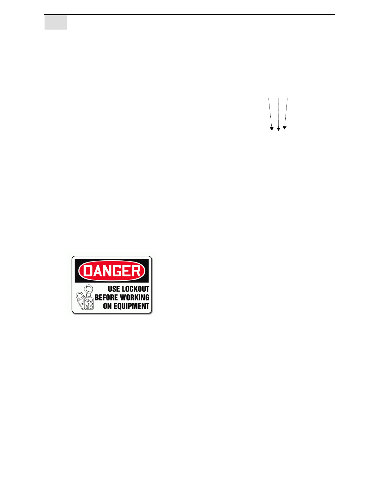
Safety Terminology of Labels
In addition to the nameplate, KVAL machines may have other warning labels or decals that provide safety information to operators. Safety labels should be clearly visible to the operator and
must be replaced if missing, damaged, or illegible.
There are three types of warning labels or decals:
• DANGER means if the danger is not avoided, it will cause death or serious injury.
• WARNING means if the warning is not heeded, it can cause death or serious
injury.
• CAUTION means if the precaution is not taken, it may cause minor or moderate
injury.
Safety Guidelines
In addition to the caution and warning labels affixed to this machine, follow the guidelines below
to help ensure the safety of equipment and personnel.
KVAL Operation/Service Manual
1-5

Never operate the machine without proper eye and
ear protection.
Protective Gear
• Never reach hands beyond safety cage. Servo
motors can unexpectedly move quickly.
• Never clear screws or hinges out of the machine
while it is running.
• Never reach into the router area to retrieve a
hinge. The router may still be running down
after shut down.
• Never perform any maintenance unless machine
is at zero state.
• Never clean the machine while it is running.
• Never walk away from the machine while it is
running.
When the Machine is ON
The compressed air system connected to this
machine should have a three-way air valve
for shut-off and pressure relief.
All cylinders on machine are under high
pressure and can be very dangerous when
activated. Before performing any maintenance or repairs on this machine turn off the
main air disconnect. Lockout and tagout
this connection.
See “Lockout Tagout Procedure” on
page 1-10.
Compressed Air
Safety First!
KVAL Operation/Service Manual
1-6
Electrical circuitry on this
machine is protected by an
approved lockable disconnect
circuit. In addition to this equipment, you must install an
approved disconnect for the
electrical power supplying this
machine.
When opening the cabinet you must first turn off the
disconnect switch. When the cabinet door is open there
is still power on the top side of the disconnect switch.
Some machines are powered by more than one supply
located at different locations. Before performing any repairs or maintenance, lockout and tagout must be installed at all locations
All maintenance and repairs to electrical circuitry should only be performed by a qualified electrician.
Still has power
in OFF position
Electrical
Prior to performing any maintenance, repairs,
cleaning or when clearing jammed debris, you
must disconnect, tag out, or lock out the electrical
and air pressure systems. This should be done in
accordance with applicable state and/or federal
code requirements.
Before Conducting Maintenance
Laser Warnings
On some machines, laser indicators are used to set boundaries. Follow the
manufacturers safety precautions.
Safety First!
KVAL Operation/Service Manual
1-7

KVAL advises that you request an on-site state
safety review of your installation of this
machine. This is to ensure conformance to any
additional specific safety and health regulations which apply in your geographic area.
Compliance with Codes and Regulations
Other Hazard Control Action
Report a Hazard
Before You Report an Accident
If you believe any part or operation of this machine is in
violation of any health or safety regulation, STOP production. It is your responsibility to immediately protect
your employees against any such hazard.
Additional detailed safety guidelines are included in the
operating instructions of this manual. KVAL will be
pleased to review with you any questions you may have
regarding the safe operation of this machine
Follow Your Company’s Safety Procedures
In addition to these safety guidelines. Your company
should have on-site and machine specific safety procedures to follow.
Safety First!
KVAL Operation/Service Manual
1-8

Lockout-Tagout Guidelines
• Place a tag on all padlocks. On the tag, each
operator must put their own name and date.
(These locks are only to be removed by the
person who signs the tag)
• If more than one person is working on the
machine, each additional person places a lock
and tag on each disconnect.
• Only each operator may remove their own
lock and tag.
Important: When many people are all working
on the same machine you will need a multiple
lockout device, such as the one shown here.
Lockout-Tagout Guidelines
Follow the P-R-O-P-E-R lockout rule of thumb.
P...... Process shutdown
R ...... Recognize energy type (electrical, pneumatic, mechanical, etc.)
O...... OFF! Shut off all power sources and isolating devices
P...... Place lock and tag
E...... ENERGY: Release stored energy to a zero-energy state
R ...... Recheck controls and test to ensure they are in the “OFF” state
KVAL Operation/Service Manual
1-9

Lockout Tagout Procedure
1. Evaluate the equipment to fully understand all energy sources (multiple electrical
supplies, air supply and pressure, spring tension, weight shifts, etc.).
2. Inform all affected personnel of the eminent shutdown, and the duration of the
shutdown.
3. Obtain locks, keys, and tags from your employer’s lockout center.
4. Turn off machine. See Chapter 2 for power down and power up procedures.
5. Turn the disconnect switches on ALL electrical and frequency panels to the OFF
position. Then push the red tab to pop it out. Place a padlock through the hole.
Place your tag on the padlock, as per the tagout guidelines below. (see illustration
below).
Note: When multiple people are working on the machine, each person needs to
have a lock on the handle in the extra holes provided.
Insert Lock into hole.
Turn Switch to the
OFF position
Lock and Tag out
Lockout Tagout Procedure
This policy is required by OSHA regulation 1910.147 and Cal OSHA’S
SB198 ruling of July 1991.
Use the following lockout procedure to secure this machine while it is
powered down. During a lockout, you disconnect all power and shut
off the air supply. Be sure to use the tagout guidelines noted below.
Pre-Steps Before Lockout Tagout
Lockout Tagout Power
KVAL Operation/Service Manual
1-10

Lockout Tagout Air Supply
6. Turn all air valves to the OFF position and place a pad-
lock through the hole (see illustration below).
NOTE: Place your tag on the padlock, as per the
tagout guidelines.
Lockout Tagout Procedure
Start Maintenance
7. Once the locks and tags are in place and all personnel are clear, attempt to operate
the machine to ensure equipment will not operate.
8. Maintenance or repairs may started.
Post Maintenance Steps
9. After maintenance is completed, the person performing the work must ensure all
tools, spare parts, test equipment, etc., are completely removed and that all guards
and safety devices are installed.
10. Before removing the locks and tags, the person who attached them shall inspect the
equipment to ensure that the machine will not be put in an unsafe condition when
re-energized.
11. The lock and tag can now be removed (only by the person(s) who placed them),
and the machine can be re-energized.
12. The tags must be destroyed and the locks and keys returned to the lockout center.
KVAL Operation/Service Manual
1-11

Zero-Energy to Start-Up
Zero-Energy to Start-Up
Starting the equipment properly is just as important as the lockout/tagout guidelines in terms of
safety.
Start-up Guidelines
The following guidelines below should be followed to start the equipment.
Inspect
The equipment must be inspected for proper adjustment before starting equipment.
Clean Up
All materials and debris must be cleaned up. Any combustible materials or old parts
used during repairs must be cleaned up and/or properly disposed of.
Replace Guards
Replace all equipment guards. If part of equipment cannot be properly adjusted after
start-up with guard on, contact the KVAL Service team. See “Getting Help from
KVAL” on page 1-14.
Check Controls
Confirm that all switches are in the “OFF” position. Please be advised that some components of the machine may start automatically when energy is restored.
Remove Locks
Each operator must remove his or her own lock and tag. This will ensure that all operators are in a safe place when the equipment is started.
Perform Visual Checks
If the equipment is too large to see all around it, station personnel around the area and
sound the personnel alarm before starting the equipment. If your operation is more
complex, your company’s comprehensive safety procedure may involve additional
steps. You will need to ask your supervisor about these procedures. The company’s
lockout procedure should be posted at each machine. On larger or long-term maintenance or installation projects, the company’s procedures must be explained to all new
operators and a copy of the company’s procedures should be posted on-site for the
duration of the work.
The Company’s procedures should also include provisions for safely handling shift
changes and changes in operators or new operators.Comprehensive lockout/tagout
may use a gang box or other system to ensure that locks are secure and not removed
without authorization.
KVAL Operation/Service Manual
1-12

Zero-Energy to Start-Up
Remember, lockout/tagout procedures work because you are the only one with the key
to your lock. Proper lockout/tagout can save lives, limbs, and money. Help make your
work environment safe for you and your fellow workers. Be sure to follow the P-R-OP-E-R lockout/tagout procedures, and that those around you do also.
Close the Cage Gate
Verify all cage gates are securely closed. Ensure all safety protocols are in effect.
KVAL Operation/Service Manual
1-13

Getting Help from KVAL
Serial Number
3 phase volts
Electrical Print
Air Print
Getting Help from KVAL
Before you seek help, first try the troubleshooting procedures.
If you are unable to resolve the problem:
1. Locate the machine’s Specification Plate and record the serial number, 3 phase
volts, electrical print number, and air print number.
2. Contact our customer support team:
• In the U.S and Canada, call (800) 553-5825 or fax (707) 762-0485
• Outside the U.S. and Canada, call (707) 762-7367 or fax (707) 762-0485
• Email address is service@kvalinc.com
• Hours:
6:00 AM to 4:00 PM Pacific Standard Time, Monday through Thursday
6:30 AM to 1:30 PM Pacific Standard Time, Friday
On-Line Help
On machines with a Beckhoff® PLC and an internet connection, our service team are able to connect, run, and troubleshoot your machine. Ask about this procedure when calling are service team
Product Return Procedure
If you’ve contacted KVAL for help and it is determined that a return is necessary, use the procedure below to return the machine or part.
Note: Non-Warranty returns are subject to a 15% restocking charge.
1. Obtain the packing slip and/or invoice numbers of the defective unit, and secure a
purchase order number to cover repair costs in the event the unit is determined to be
out of warranty.
2. Reason for return: Before you return the unit, have someone from your organization
with a technical understanding of the machine and its application include answers to
the following questions:
KVAL Operation/Service Manual
1-14

Getting Help from KVAL
• What is the extent of the failure/reason for return? What are the relevant error messages or error codes?
• How long did it operate?
• Did any other items fail at the same time?
• What was happening when the unit failed (e.g., installing the unit, cycling power,
starting other equipment, etc.)?
• How was the product configured (in detail)?
• Which, if any, cables were modified and how?
• With what equipment is the unit interfaced?
• What was the application?
• What was the system environment (temperature, spacing, contaminants, etc.)?
3. Call KVAL customer support for a Return Material Authorization (RMA). When
you call:
• Have the packing slip or invoice numbers available.
• Have the documented reason for return available.
4. Send the merchandise back to KVAL.
• Make sure the item(s) you are returning are securely packaged and well protected
from shipping damage
• Include the packing slip or invoice numbers.
• Include the documented reason for return.
• Include the RMA number with the parts package.
KVAL Operation/Service Manual
1-15

How to Download the Service Application
1. To download the application, go
the KVAL website (http://
www.kvalinc.com
)
2. At the KVAL website, select the
Support tab. Follow the instruc-
tions on the Support web page.
3. Click the Download button to
download the application that
allows the KVAL technician to
have access to the operator station.
4. After the download is com-
pleted, double-click the program
icon.
Note: Web browsers have different methods of downloading programs. Below are
samples of i.e Explorer and Google web browsers.
Sample of Google Browser: Located at the
bottom left of the screen.
Sample of i.e Explorer: Located at the bottom of the screen. select the arrow and
choose Save and Run
How to Download the Service Application
On machines with Windows (8.1 / 8 / 7 / Vista / XP) and an internet connection, our service team
are able to connect, run, and troubleshoot your machine by way of the operator station.
Download Application
.
KVAL Operation/Service Manual
1-16
5. A pop-up window is displayed.
Accept the request to run the program.
Note: Security settings may differ from
plant to plant. If issues occur, contact
your IT department.
6. The interface of the KVAL Support App will be dis-
played. Enter your name in the Your Name field.
The fields are described below:
Session code: An internal number to track this
machine. It is auto filled.
Allow Remote Control: Program is ready to allow
technicians to access machine computer
Your Name Field: Enter your name. The KVAL technician will use this field to identify this machine.
Description: Enter machine Serial number and
issue.
Indicator: Green indicates there is a good connection to the service center. If red, there could be an
issue with a LAN connection. Check the connections
in the plant.
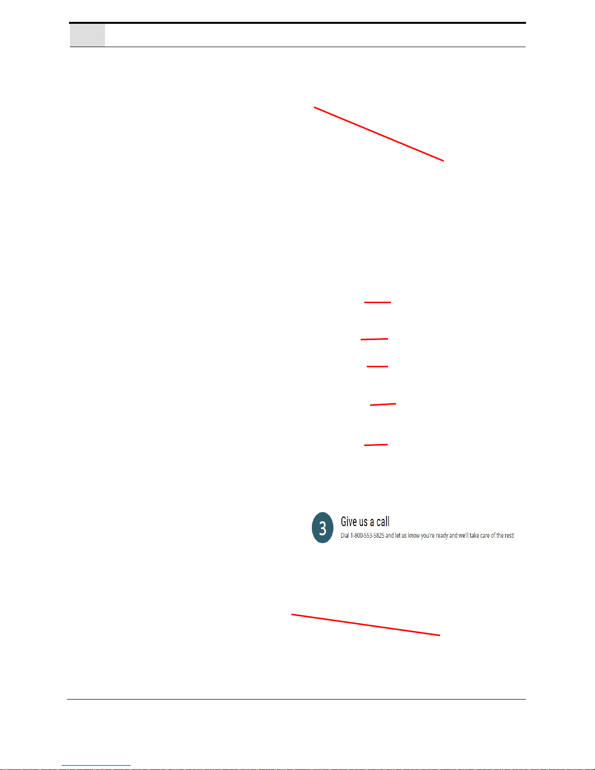
7. After the KVAL Support App is
loaded and completed, call the
KVAL service center(1-800-553-
5825) and have the technician connect to the machine computer.
8. Click the Allow button to give the
KVAL service technician permission to access the operator station.
We are now ready to troubleshoot.
How to Download the Service Application
KVAL Operation/Service Manual
1-17

How to Download the Service Application
Page Intentionally Left Blank
KVAL Operation/Service Manual
1-18
 Loading...