

KVAL INC.
INSTRUCTION MANUAL
.
Door Pre-Hanging Machine
Commander
REV.1

1

R
CONGRA TULATIONS ON YOUR PURCHASE OF A NEW KVAL
COMMANDE
SERIAL No._____________________________________________
DATE OF PURCHASED___________________________________
This manual is designed with safety in mind. We at KVAL want to begin FAST and
SAFE production as soon as possible. It is very important that all OPERATORS
and MAINTENANCE personnel read this manual thoroughly. We have included
important safety information that will help prevent serious injury; as well as
complete maintenance, and troubleshooting instructions.
Proper operation and maintenance of your new KVAL machine will guarantee
many years of trouble-free, fast-paced production.

KVAL INC.
OPERA TOR’S & P ARTS MANU AL
For further information about this manual or other Kval Incorporated products, contact the Customer Support Department, Kval
Incorporated, 825 Petaluma Boulevard South, Petaluma, CA 94952. In the U.S and Canada, call (800) 553-5825 or fax (707) 762-
0485. Outside the U.S. and Canada, call (707) 762-7367.
Kval Incorporated welcomes your opinion regarding this document. Please send them to the Customer Support address shown
above.
Copyright 2005 Kval Incorporated. All rights reserved.
All other products are trademarks or registered trademarks of their respective holders, all rights reserved. Reference to these products
is not intended to imply affiliation with or sponsorship of Kval Incorporated.
Proprietary Notice
This document contains confidential and trade secret information, which is proprietary to Kval, Inc. (“Kval”), and is protected by
laws pertaining to such materials. This document, the information in this document, and all rights there to are the sole and exclusive
property of Kval, are intended for use by customers and employees of Kval, and are not to be copied, used, or disclosed to anyone,
in whole or in part, without the express written permission of Kval. For authorization to copy this information, please call Kval
Customer Support at
Copyright 2005 Kval Incorporated. All rights reserved.
825 Petaluma Blvd So.
Phone (707)-762-7367 • Fax (707)-762-0485
www.kvalinc.com

Table of Contents
OPERATOR’S & PARTS MANUAL........................................................................................................ III
CUSTOMER SERVICE INFORMATION..................................................................................................1
RETURNING PARTS / EQUIPMENT TO KVAL.....................................................................................2
WHEN YOU CALL:......................................................................................................................................... 2
WHEN SENDING MERCHANDISE BACK: ........................................................................................................2
GETTING STARTED....................................................................................................................................3
SAFETY FIRST DANGER!..........................................................................................................................5
PROCEDURE.................................................................................................................................................6
LOCK OUT AND TAG OUT PROCEDURE..............................................................................................7
LOCK RULES................................................................................................................................................9
SAFETY GUIDELINES ..............................................................................................................................13
ELECTRICAL.........................................................................................................................................13
COMPRESSED AIR:..............................................................................................................................13
OPERATING SAFETY: .........................................................................................................................13
COMPLIANCE WITH CODES AND REGULATIONS:...................................................................... 13
OPERATORS TRAINING:.....................................................................................................................13
OTHER HAZARD CONTROL ACTION:..............................................................................................13
SPECIFICATIONS......................................................................................................................................15
UNCRATING THE COMMANDER..........................................................................................................16
COMMANDER INSTALLATION.............................................................................................................16
REMOUNTING COMPONENTS:....................................................................................................................16
BOLTING THE OPTIONAL 555 DOOR SIZER:..............................................................................................16
LEVELING THE COMMANDER AND THE OPTIONAL 555 DOOR SIZER:.....................................................16
ELECTRICAL HOOK UP:.............................................................................................................................16
ROTATION CHECK:.....................................................................................................................................16
ANCHORING THE MACHINE TO THE FLOOR..................................................................................19
MAINTENANCE SCHEDULE FOR COMMANDER.............................................................................21
DAILY:.......................................................................................................................................................21
WEEKLY:..................................................................................................................................................21
MAY AND DECEMBER CHECK UPS..................................................................................................21
LUBRICATION REQUIREMENTS..........................................................................................................23
Linear Bearings: .....................................................................................................................................23
Flange Bearing:......................................................................................................................................23
Lubricate special high speed bearings:...................................................................................................23
Perske High Frequency Motors:.............................................................................................................23
Approved Lubrication Products:.............................................................................................................23
Lubricator Adjustments:.........................................................................................................................23
Gear Motor Lubrication Requirements:.................................................................................................23
Mist Oil Lubrication:...............................................................................................................................24

Priming the Lubricator:..........................................................................................................................24
CONTROL PANEL OPERATIONS..........................................................................................................27
JAMB CLAMP PEDAL:................................................................................................................................. 27
DOOR CLAMP: ............................................................................................................................................27
DOOR WIDTH ADJUSTABLE:......................................................................................................................27
CONTROL TRANSFORMER:......................................................................................................................... 27
START MACHINE:.......................................................................................................................................27
BACK SECTION/ BOTH / FRONT SECTION: ................................................................................................ 27
LOCK BORE OFF / REG. / DEEP:................................................................................................................27
BOLT DRILL OFF/ ON: ............................................................................................................................... 27
FACE PLATE OFF/ REG. / EXTEND TIME:..................................................................................................28
EXTEND HINGE ROUTER TIME OFF / ON:.................................................................................................28
FRONT SECTION SKIP #2 / ALL:.................................................................................................................28
AUXILIARY CONTROL PANEL..............................................................................................................28
EMERGENCY STOP: ....................................................................................................................................28
START SEQUENCE:...................................................................................................................................... 28
DOOR STOP:................................................................................................................................................29
LOCK LOCATION (OPTIONAL):..................................................................................................................29
FEED MODE (OPTION): ...........................................................................................................................29
AUTO IN:.....................................................................................................................................................29
AUTO IN / OUT:...........................................................................................................................................29
Door Only:...............................................................................................................................................29
Door & Jamb:..........................................................................................................................................29
FEED (OPTION):.........................................................................................................................................29
JOG FWD: ..................................................................................................................................................29
JOG REV.....................................................................................................................................................29
START SEQUENCE (FRONT/BACK) (OPTION):.................................................................................29
FRONT:........................................................................................................................................................29
BACK:.......................................................................................................................................................... 29
FRONT SECTION....................................................................................................................................31
COMMANDER HINGE SECTION:..........................................................................................................31
HINGE LOCATIONS:....................................................................................................................................31
STANDARD HINGE CENTER SET UP:..........................................................................................................31
SETTING THE OFF FEED STOP: ..................................................................................................................31
HINGE SIZE:................................................................................................................................................32
HINGE BACKSET DOOR:.............................................................................................................................32
HINGE BACKSET JAMB:..............................................................................................................................32
EXTERIOR DOORS: .....................................................................................................................................32
CHANGING CHIPOUT BLOCKS: ..................................................................................................................33
MACHINING NEW HINGE CHIPOUT BLOCKS: ...........................................................................................33
SETTING THE JAMB STOPS:........................................................................................................................33
ALTERNATIVE SET UP FOR PRE HANGERS:...............................................................................................34
DOUBLE BEVELED DOORS: ........................................................................................................................34
DALTON TORQUE LIMITER OSD:..............................................................................................................35
DOOR HINGE BACKSET: BOTTOM PIN..............................................................................................35
SETTING UP FOR A CUT CONTINUED......................................................................................................... 36

COMMANDER EXTERIOR DOOR REVEAL ADJUSTMENT ...........................................................37
HIGH FREQUENCY ROUTER DEPTH ADJUSTMENT:.....................................................................38
SETTING UP THE BACK SECTION:...................................................................................................41
COMMANDER LOCK SECTION:............................................................................................................41
LOCK SECTION LOCATION: ..........................................................................................................................41
LEFT AND RIGHT SHIFT WITH MULTI-STOP FOR LOCKS SECTION (OPTIONAL):............................41
LOCK BORE...........................................................................................................................................43
LOCK BORE OFF, REG, DEEP:..........................................................................................................43
LOCK BORE DIAMETER.....................................................................................................................43
LOCK BORE BACKSET ........................................................................................................................43
MAKE SURE CHIPOUT AND DRILL ARE ALIGNED PROPERLY!................................................44
ADJUSTING BACKSET TURRET BOLTS:.........................................................................................44
TWO STAGE FACE DRILLING...........................................................................................................44
FACE PLATE SET UP:..................................................................................................................................45
PLATE LENGTH: .........................................................................................................................................45
PLATE WIDTH:............................................................................................................................................45
PLATE ROUTER DEPTH:......................................................................................................................45
SWITCHING TO BEVEL PLATES:...................................................................................................... 46
SIDE DRILL (LATCH HOLE): ..............................................................................................................46
TROUBLE SHOOTING..............................................................................................................................49
LIMIT SWITCHES ..................................................................................................................................49
PHOTO EYES........................................................................................................................................... 50
GENERAL AIR CIRCUITRY TROUBLE SHOOTING......................................................................51
To change cylinder extension speed:......................................................................................................52
To change cylinder retraction speed:......................................................................................................52
BASIC ELECTRICAL TROUBLE SHOOTING ..................................................................................53
IF THE POWER STOPS DURING NORMAL OPERATIONS: DE-ENERGIZED:..........................53
FRONT SECTION DOES NOT FUNCTION PROPERLY..................................................................55
FRONT SECTION IS NOT TURNED ON AT THE CONTROL PANEL:........................................55
THE SIX SHOOTER IS NOT MOVED FULLY TO THE RIGHT:.....................................................55
THE THROUGH BEAM LENSES ARE DIRTY:.................................................................................55
SOMETHING IS WRONG WITH THE CYLINDERS THAT MOVE THE FRONT SECTION.... 57
MOVE FRONT SECTION TO THE “IN POCKET POSITION” THEN DO THE FOLLOWING:..57
ONE OF THE CYLINDERS IS BAD:................................................................................................... 57
THE ALIGNMENT OF THE CYLINDER SHAFTS IS OFF: .................................................................57
THERE IS AND OBSTRUCTION BLOCKING THE THROUGH BEAM:........................................57
GUARDS ARE MISS-ALIGNED:..........................................................................................................57
THROUGH BEAMS ARE NOT LINED UP:........................................................................................57
ONE OR MORE THROUGH BEAMS ARE BAD:............................................................................... 58
ENVIRONMENT TOO COLD:.............................................................................................................. 58
WIDTH ADJUSTS DOESN’T FUNCTION PROPERLY ....................................................................59
UNSATISFACTORY HINGE POCKETS..............................................................................................59
FUZZY HINGE POCKETS:...................................................................................................................59
RING AROUND THE POCKET:........................................................................................................... 59
FEED SYSTEM SURGING:..................................................................................................................59
FEED SYSTEM MOVING DOORS TO FAST:.................................................................................... 59
SETTING UP BOLT PLATE LENGTH:...............................................................................................60
LOCK BORE TWO STAGE FACE DRILLING:...................................................................................60
PLANNED MAINTENANCE PROGRAM ...............................................................................................65


COMMANDER PRE-HANGING DOOR MACHINE
Chapter
1
Customer Service Information
KVAL is happy to help its customer make the most of their investment, and help solve any problems
that may occur. When you call, please have the electrical print, air print number, and the serial number
of the machine ready, so that we are able to accommodate your needs efficiently.
HOURS
6:30 AM to 4:30PM Pacific Standard Time – Monday thru Friday
Phone: (707) 762-7367
Fax: (707) 762-0485
www.kvalinc.com
This page contains Kval, Inc. proprietary information and is not to be duplicated or disclosed to unauthorized persons.
1

Returning Parts / Equipment to KVAL
Before returning parts and/or equipment to Kval Inc. please call KVAL at (707) 7627367 to receive a RMA # (Return Merchandise Authorization number).
* No t e
Non-Warranty returns are subject to 15% Re-stocking Charge.
When you call:
1. Have your Packing Slip and/or invoice #’s available
2. Have reason for return available
When sending merchandise back:
1. Make sure that the Item(s) you are returning are securely packaged and well protected from
shipping damage.
2. Including Packing Slip #
3. Include your RMA # on the outside of the package so our shipping receiver will see it.
Kval tries hard to satisfy its Customers, if you have any questions concerning merchandise purchased
through KVAL, please call.
This page contains Kval, Inc. proprietary information and is not to be duplicated or disclosed to unauthorized persons.
2

Getting S tarted
Your new KVAL Machine arrives at your plant crated, banded, taped and has painted set
collars on all shafts; keeping all of the precision moving parts secure during shipping.
1. Move the machine as close to the area it will be stationed before removing the crate to
protect against damaging the machine with the forklift.
2. Remove the machine from the crate. Be careful! Anytime the machine is lifted to
remove the skids there is a chance of the machine dropping suddenly, and damaging
the machine, or injuring people near the machine.
3. Remove all painted set collars from the shafts. Just about every shaft on the machine
has set collars to secure the moveable assembly mounted to the shafts.
4. Take off any tape securing the various buttons, switches and knobs.
5. Level your KVAL machine by putting metal shims underneath the corners of the base.
Leave a clear shot from the bolt holes in the foot pads to your shop floor. Now, make
sure the machine won’t rock back and forth.
6. Once the machine is level, anchor it to the floor so that it won’t move across the floor
during operation. KVAL recommends a ½ RED HEAD, TRUE BOLT ANCHOR in
each of the foot pads. When drilling the concrete for the anch or bolts use a 5/8 bit.
Note
KVAL wants to provide the industry’s safest and highest quality wood working
machines. The following page is a quality control and safety checklist. Our technicians
have already performed an initial quality control check before shipping your machine.
Please review the checklist and return “Acknowledgment Copy” to KVAL Verifying
complete contents.
This page contains Kval, Inc. proprietary information and is not to be duplicated or disclosed to unauthorized persons.
3

This page contains Kval, Inc. proprietary information and is not to be duplicated or disclosed to unauthorized persons.
4

Chapter
2
Safety First Danger!
This section contains important safety information. Failure to follow these safety guidelines may
subject the operator to physical hazards that may resu lt in serious bodily arm, or death.
This page contains Kval, Inc. proprietary information and is not to be duplicated or disclosed to unauthorized persons.
5

Responsibility
It is the responsibility of each employee to maintain safe working conditions in his or her area.
Failure to understand and correctly follow this procedure is direct violation of safety rules and
regulations. Violations of this policy can lead to severe injury.
PROCEDURE
To lockout or tag out a piece of equipment, the following steps must be taken:
1. Assess the equipment to fully understand all energy sources (multiple electrical supplies air
and/or hydraulic pressures, spring tension, weight shifts, etc.)
2. Inform all affected personnel of the eminent shutdown, and the duration of the shutdown.
3. Obtain lock and tags from employer.
4. Shutdown machine(s) by normal means, i.e., disconnect switch(s), air pressure relief valve(s),
on/off button, etc. NOTE: Control power switches do not serve as adequate shutdown devices.
The main source(s) of energy must be disconnected as well. Also, ensu re that all mechanically
stored energy has been released, i.e., lifting booms lowered to bottom of travel, carriages in
“HOME” position etc., No one may remove a tag or lock installed by someone else. Only the
person who attached the tag or lock is authorized to remove it.
5. Once the lock and tag is in place, the employee must try to operate the machine to ensure all
energy sources are defeated.
6. When maintenance or repairs are completed, the pe rson that did the work m ust ensu re all tools,
spare parts, test equipment, etc. are completely removed and that all guards and safety devices
are installed.
7. Before removing the lock and tag, the person who attached them shall inspect the equ ipment to
ensure that the machine will not be put in an unsafe condition when re-energized.
8. The lock and tag can now be removed (only by the person who place them), and the machine
can be re-energized.
9. The tag shall be destroyed and the lock and key returned to the lockout center.
In addition to safety concerns, this policy is required by OSHA regulation 1910.147 and Cal
OSHA’S SB198 ruling of July 1991.
This page contains Kval, Inc. proprietary information and is not to be duplicated or disclosed to unauthorized persons.
6
Lock out and Tag Out Procedure
This page contains Kval, Inc. proprietary information and is not to be duplicated or disclosed to unauthorized persons.
7

1. P .... PROCESS SHUTDOWN
2. R .... RECOGNIZE ENERGY TYPE
3. O .... OFF - SHUT OFF ISOLATING DEVICES
4. P .... PLACE LOCK AND TAG
5. E .... ENERGY RELEASE STORED ENERGY (0 ENERGY STATE)
6. R .... RECHECK CONTROLS AND RETURN TO PROPER SETTING
ENERGY TYPES
Recognize the Types of Energy to Shut Down
1. Electrical Energy
2. Hydraulic and/or Pneumatic Energy
3. Fluids and Gases
4. Mechanical Energy
ACCIDENT SITUATIONS
• Accident Start Up
Equipment can accidentally be turned on and your hands may be in the point of operation or while you are
inside.
• Electrical Shock
You can be accidentally electrocuted if the power is still on or if it is accidentally turned on.
• Hazardous Materials
If released can go into confined areas or the work area.
• Stored Energy
You could be caught in equipment that can move due to stored energy, even with the power off.
The Solution Is Quite Simple — These Accidents Can Be
Prevented Using The P-R-O-P-E-R Lock-Out Procedures.
This page contains Kval, Inc. proprietary information and is not to be duplicated or disclosed to unauthorized persons.
8

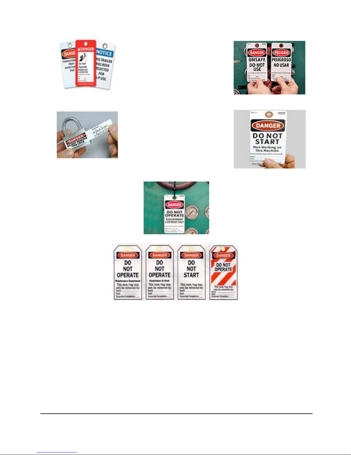
LOCK RULES
1. Use an appropriate “Lock-Out Device”, such as Lock Tongs, or a Lock Tag. Each person must attach his or
her own lock to the Lock-Out Device.
2. Identify Locks
Each lock will be identified by a number or a name. A lock without a tag is not good enough. Additional
information that identifies the person / persons doing the work must be on the tag. Also the type of work that
is being performed should be on the tag.
3. Sign The Tag
In some instances one tag is enough, however, the tag must be signed by each worker. In some
circumstances a supervisor will also need to sign the tag.
4. One Key Per Lock
5. Never give your key to anyone else.
Recheck controls and return to proper setting
P-R-O-P-E-R ELECTRICAL LOCK-OUT
P Process Shut Down
Open disconnect before pulling the plug. Shut down process or equipment.
R Recognize Energy Type
Recognize the correct power source.
O Off! -Shut Off all Power Controls
Shut off machine and electrical energy at both machine and main power switch. There may be more than
one source of power and all must be shut off. If necessary,
electrical drawings and a supervisor may need to be involved.
P Place Lock-Out Device, Lock and Tag
Each person working on equipment needs to put his or her lock on the switches and sign the tag.
E Energy - Release Stored Energy
Bleed electrical capacitors if any.
R Recheck Controls and Return To “OFF” Setting
Recheck the start button and properly test that you have
zero energy state.
This page contains Kval, Inc. proprietary information and is not to be duplicated or disclosed to unauthorized persons.
9

P-R-O-P-E-R HYDRAULIC AND/OR PNEUMATIC
LOCK-OUT
P Process Shut Down
Shut down process using recommended procedures.
R Recognize Energy Type
Recognize all sources of energy – the electric that powers the pumps or compressors, and the air or
hydraulic valves themselves.
O Off! -Shut off all Power Controls
Shut off each energy type.
P Place Lock-Out Device, Lock and Tag
The shape or location on some valves may be difficult to lock out. If there is not a specific lock out tag out
procedure in place you should ask your supervisor.
E Energy - Release Stored Energy
Bleed the stored energy by bleeding the air line and draining the compressor, or by using other prescribed
methods. Keep in mind that when bleeding stored energy
it could cause some parts of the equipment to move, as it is being held by the stored energy.
R Recheck Controls and Return To “OFF” Setting
Return controls to proper settings.
P-R-O-P-E-R FLUIDS AND GASES LOCK-OUT
P Process Shut Down
Shut down process using recommended procedures.
R Recognize Energy Type
Recognize the material and its hazards. If material is hazardous, use the proper protective equipment. Even
water can become a hazardous fluid under high
pressure.
O Off! -Shut Off all Isolating Valves
If a job requires breaking in to a line close off isolating device, blanking if necessary. Some valves may be
difficult to lock out. A locking bar or chains may be
needed. Check with supervisor.
P Place Lock-Out Device, Lock and Tag
Sign tag.
E Energy - Release Stored Energy
Release pressure and drain to achieve zero energy state.
R Recheck Controls and Return “OFF” Setting
Recheck line and test properly and make sure you have zero energy state.
This page contains Kval, Inc. proprietary information and is not to be duplicated or disclosed to unauthorized persons.
10

P-R-O-P-E-R MECHANICAL ENERGY LOCK-OUT
Mechanical Energy may be released at the point of operation, or where two or more
points of operation come together. This is where you might get caught. In most cases
blocking mechanical energy is done in addition to shutting off the primary source, such as
electrical, hydraulic and pneumatic. Some examples include inserting restraining pins or
bars in the point of operation or block under a lift. In cases where these blocks to
mechanical energy are not locked in place, they should not be the primary means of
shutting off energy. Mechanical energy can also be stored.
1 Gravity
Things that are up can fall of their own weight. Pins or blocking may be required.
2 Springs
BOING! can spell DEATH. Release tension or compressed springs by using methods
prescribed by the equipment manufacturer.
3 Tensions
Things under tension can spring in. Release tension by using prescribed method by
equipment manufacturer.
P Process Shut Down
Shut down the process.
R Recognize Energy Type
Recognize all forms of energy – Need to be shut off, such as electrical and mechanical.
Mechanical is usually a secondary energy source closest to point of operation.
O Off! -Shut Off all Power Controls
Such as switches, valves and other isolating devices.
P Place Lock-Out Device, Lock and Tag
Place lock on the isolating device and sign tag.
E Energy - Release Stored Energy
Release, spring or tension to achieve, zero energy state.
R Recheck Controls and Return To “OFF” Setting
This page contains Kval, Inc. proprietary information and is not to be duplicated or disclosed to unauthorized persons.
11

ZERO ENERGY START UP
Zero Energy State to Start-up to Operating State
Starting the equipment is just as important as Lock-Out/Tag-Out in terms of safety.
Start-up
• Inspection
• Clean up
• Replace guards
• Check controls
• Remove locks
• Visual checks
Inspect
When work is finished the equipment must be inspected for proper adjustment before starting equipment.
Clean Up
All materials and debris must be cleaned up. Any combustible materials and old parts used during repairs
must be cleaned up.
Replace Guards
Replace all guards to the equipment. If adjustments can not be made with the guard on after start-up, leave
off only the ones to be adjusted after start-up.
Check Controls
Make sure all switches are in the off position. In some cases the machine can start automatically when
energy is restored.
Remove Locks
Each person must remove his or her own lock or tag. This will ensure you are in a safe place when the
equipment is started.
Visual Checks
If the equipment is too large to see all around it, station personnel around the area and sound the personnel
alarm before starting the equipment. If your operation is more complex, having many pieces of equipment
and a lot of people, a comprehensive Lock-Out/Tag-Out procedure may involve additional steps. You will
need to ask your supervisor about these procedures. A specific lock out procedure may be posted at each
machine. On larger or long term maintenance projects or installation projects, the procedures should be
explained to all participants and a copy of the procedures posted on site for the duration of the work.
Provisions which ensure protection during shift changes when contractor or outside help is used also need to
follow the Lock-0ut/Tag-Out Procedures. Comprehensive Lock-0ut/Tag-Out may use a gang box or other
system to ensure that locks are secure and not removed without authorization.
Remember Lock-Out Tag-Out procedures work because you are the only one with the key to your lock.
Proper Lock-0ut/Tag-Out can save lives, limbs and money. Help make your work environment safe for
yourself and your fellow employees. Make sure you follow the P-R-OP-E-R Lock-0ut/Tag-Out procedures,
and that those around you do also.
YOUR LIFE MAY DEPEND ON IT.
© 2004 American Concrete Pipe Association (ACPA). All Rights Reserved.
This page contains Kval, Inc. proprietary information and is not to be duplicated or disclosed to unauthorized persons.
http://www.concrete-pipe.org/sab.htm
12

Safety Guidelines
ELECTRICAL
Electrical circuitry on this machine is protected by an approved lockable disconnect circuit. In
addition to this equipment, you must install an approved disconnect for the electrical power
supplying this machine
COMPRESSED AIR:
The compressed air system connected to this machine should have a three-way air valve for
shut-off and pressure relief. The air supply providing the pressure to this machine also has a
three-way air valve for the supply line.
OPERATING SAFETY:
Prior to changing any cutters or doing any maintenance work, you must disconnect, tag out, or
lock out the electrical, air pressure and hydraulic systems. This should be done in accordance
with the State and/or Federal code requirements.
COMPLIANCE WITH CODES AND REGULATIONS:
It is advised that you request an on-site State safety review of your installation of this machine.
This is to ensure conformance to any additional specific safety and health regulations which
apply in your area.
OPERATORS TRAINING:
You must ensure that all operators of this machine be tra ined to know the potential electrical
hazards, pressure pinch points, rotating cutters, and other similar hazards. It is also your
responsibility to train the operators, or potential operators on how to operate the m achine
safely.
OTHER HAZARD CONTROL ACTION:
If you believe that any part or operation of this machine is in violation of any health or safety
regulation, it is your responsibility to immediately protect your employees against any such
hazard and bring the matter to our attention for review and correction, if deemed advisable.
You will not that additional detailed safety guidelines are in cluded in th e operatin g instructio ns
of this manual. We will be pleased to review with you any questio ns you may have regarding
the safe operations of this machine.
This page contains Kval, Inc. proprietary information and is not to be duplicated or disclosed to unauthorized persons.
13

This page contains Kval, Inc. proprietary information and is not to be duplicated or disclosed to unauthorized persons.
14

Chapter
3
SPECIFICATIONS
The Commander is KVAL’s best-selling and most flexible door machine. It automatically machines
up to four hinges and also machines for cylindrical lock or dead bolt. Since the Commander can
simultaneously route hinge jambs, it is ideal for distributors of architectural doors and residential prehangers.
The Commander is designed to route and bore for lock and hinges in flush or stile and rail doors up to
2-1/4” thick by 4’ wide and 9’ long and wit a minimum width of 18”. It also accommodates raised
panels or molding up to ¾” thick. The jamb clamping system compensates for jam b thickn ess and will
accept flat, split and rabbeted jambs up to 1-1/2” thick with a 5/8” stop, or 1-7/8” thick overall. There
is no limitation on jamb width.
Hinge Routing: Automatic hinge-routing unit accommodates both ¼” and 5/8” radius hinges up to 51/2” utilizing turret-stop adjustments. Hinge centers are adjusted by positioning collars on a removable
plug-in shaft below the router and sliding jamb clamping fixtures into position. Extra shafts may be set
up and “plugged in” for rapid hinge center adjustments. During the routing sequence the router
automatically travels along the removable shaft to each collar and dapps the pocket. Full hinges up to
4” X 4” can be attached to the doors and jambs.
Lock: Face bore is adjustable from 2-3/8” to a 5” backset. The faceplate is adjustable for square or
bevel up to 3-1/2 degrees from 1” X 2-1/4” up to 1-1/4” X 12”. Self-Centering clamp system ensures
accurate latch and faceplate machining regardless of door thickness. Both drill motors feature Accuflex collet chucks so standard straight shank tooling may be used.
This page contains Kval, Inc. proprietary information and is not to be duplicated or disclosed to unauthorized persons.
15

Uncrating the Commander
Commander Installation
Remounting Components:
Slide the routers back into their bases and plug them in. While testing the machine, remove all router
bits. This includes drill bits for the lock. Remount the main electrical box to the commander’s rear leg
on the in-feed end.
Bolting the Optional 555 Door Sizer:
Rest the off-feed end of the 555 on the leveling brackets welded to the commander’s frame. Screw in
the mounting bolts from the 555 into the commander finger tight. Align and drive in the roll pins from
the inside of the commander’s frame. Tighten the bolts and fasten the 555 electrical junction box back
in place. An electrician or the Kval tech rep will reconnect the wires disconnected fro shipping.
Leveling the Commander and the Optional 555 Door Sizer:
Set a level on the Commander’s hard board (Ryertex) runner, below the jamb clamps and insert sheet
metal shims under the low leg. Level width wise by place a level on the 1 ½” shafts supporting the
lock machining carriage, again using sheet metal shim s to bring up the low le g.
Electrical Hook Up:
We recommend using a licensed electrical contractor to hook the machine into your buildings electrical
system. Code approved circuit interruption equipment and lockable wall mounted disconnects are
necessary for both the single and three phase services; otherwise, the service wires connected to the
main panel on the backside of the Commander will not shut off for maintenance or repair work.
Amperage varies depending on the optional equipment; check the stamped amperage rating on the
specification plate. Once the wall disconnects are wired; tag and lock them out. The single phases
connect at the labeled block inside the panel. These connector blocks allow either 110V service with a
jumper between “hot” terminals or 220V split phase with as single common. Three phase wires are
connected to the panel disconnect switch—remove the shield at the right of the fuse block to make
connections. Be sure to connect an appropriately sized grounding wire to the ground lug.
Rotation Check:
Close the panel door and switch on the power disconnect. Pull on the control transformer control
panel. Turn off all the selector switches except the lock bore drill, and press the master start button
followed by the emergency stop button. If the rotation of the lock drill is wrong, lock out both the
single and three phase wall disconnects, then switch two of the tree phase leads connected to the
commander’s main panel disconnect switch.
Air Service:
This page contains Kval, Inc. proprietary information and is not to be duplicated or disclosed to unauthorized persons.
16

The standard Commander is rated at 8 CFM. Check the spec plate if the optional H-1000 or 555 was
ordered with your Commander. Air should be supplied inside the left rear leg to the Filter/ Regulator /
Lubricator module. Once the machine is up and running, sight through the glass on top of the
lubricator, and turn the adjustment screw so one drop every two cycles is fed to the system. Check the
filter bow daily and empty if its more than half full of water.
Finally, if your plant is located in a humid area we recommend a air dryer on your compressed air
system.
This page contains Kval, Inc. proprietary information and is not to be duplicated or disclosed to unauthorized persons.
17

This page contains Kval, Inc. proprietary information and is not to be duplicated or disclosed to unauthorized persons.
18

ANCHORING THE MACHINE TO THE FLOOR
When you have set-up and test run your machine to ensure that it is feeding the material properly KVAL
recommends anchoring the machine to the floor with ½ Red head, True Bolt Anchors in each of the foot pads. An
alternative way to bolting the machine, you may want to use Epoxy and hardened threaded rods to prevent the bolts
from vibrating loose. KVAL doesn’t require the use of epoxy though its added fastening strength is significant.
Standard Anchoring Instructions:
* With machine in place and leveled, drill 3”
deep holes in the concrete using a 5/8” dia.
masonry bit, using the mounting hole as a guide.
* Clean out holes with an air compressor to
ensure that the anchor heads get a firm bite on
the walls of the holes.
* Insert anchors through the mounting holes in
the foot pads and into the holes you have drilled
into the concrete. If an anchor’s expansion
sleeve binds inside the hole, simply tap the bolt
head with a hammer until the binding stops.
* Tighten bolts until they are snug. Avoid over
tightening the bolt as this may cause the head of
the bolt to break.
Anchoring Instructions using Epoxy:
* With machine in place and leveled, drill 3”
deep holes in the concrete using a 9/16” dia.
masonry bit, using the mounting hole as a
guide.
* Clean out holes with a air compressor.
Complete hole preparation with use of a nylo n
brush (do not use wire brush).
* When starting a fresh cartridge of anchoring
epoxy, epoxy must be an evenly blended light
gray color. Insert nozzle into the bottom of the
hole. Fill hole to ½ the hole depth.
* Insert 1/2”, (hardened) threaded rod into the
bottom of the hole using a slow twisting
motion. This insures the epoxy fills voids and
crevices. Hardening begins in 7 minutes @
room temperature.
* After recommended cure time, bolt in place.
This page contains Kval, Inc. proprietary information and is not to be duplicated or disclosed to unauthorized persons.
19

This page contains Kval, Inc. proprietary information and is not to be duplicated or disclosed to unauthorized persons.
20

Maintenance Schedule
Maintenance Schedule
KVAL recommends the following maintenance schedule to ensure that the machine operates
properly. Refer to this section for steps to perform maintenance.
Daily, Monthly, Six Month Maintenance
Daily Preventive Maintenance
Op Operation Description
Clean
Check
Clean
Check
Clean
Check
Check
Blow off dust from the entire machine.Wipe down the outside of the machine with a
clean dry cloth.
Check tooling for wear.
Wipe of f the photo eyes with a clean dry cloth, and check to ensure that all fastening nuts
are snug.
Check the air pressure to make sure it is set at 80 psi to100 psi.
Empty any Dust Collection Units.
Check for obstructed flow when excessive sawdust appears.
Check the air filter water trap. Empty if full.
Weekly Preventive Maintenance
Op Operation Description
Check
Clean
Check
Check the machine for smooth motion through a complete door cycle
Clean linear bearings and the chrome shaft with a clean dry cloth, then lubricate.
Check all air lines & electrical wiring for kinks or rubbing.
LUBE
Refill lubricator with an ISO 32 standard hydraulic oil (KVAL part# SYSLUBG)
Six Month Preventive Maintenance
Op Operation Description
Clean
LUBE
Clean
Tighten
Back-up
LUBE
Wa sh filter and lubricator bowls with soapy water.
Grease all bearings and tighten all bolts. Access to some grease fittings is difficult and
will require a special needle point grease tip (supplied with your system).
Clean and lubricate all slides and cylinder rods with dry silicone spray.
Tighten all bolts.
Backup computer software.
Lubricate linear bearings and chrome shafts with silicone.

Maintenance Schedule
Lubrication Schedule
KVAL recommends the following lubrication schedule to ensure that the machine operates properly.
TABLE 3-1. Recommended Lubrication Schedule
Type of Assembly Recommended Schedule Recommended Lubrication Type
Linear Bearing
Every 250 Hours of Machine Operation Dura-Lith Grease (KVAL P/N Lube EP-2)Pillow Block Bearing
Flange Block Bearing
Ball Screw Every 80 Hours of Machine Operation
Air Line Lubricator One drop of oil every 2 or 3 cycles
Check the lines every week to two weeks
Gear Box 2000 Hours of Machine Operation or six months
of operation
Either lubricant listed below is approved
to use.
• KVAL P/N SYSLUBG
• Chevron AW Hydraulic Oil 32
• G-C lubricants light AW R&O
• Mobile DTE 24
• Shell Tellus32
• Gulf Harmony 32
• AGMA #8 gear lube
• MOBILUBE HD 80 W-90
• or equivalent

This page contains Kval, Inc. proprietary information and is not to be duplicated or disclosed to unauthorized persons.
22

LUBRICA TION REQUIREMENTS
Linear Bearings:
If bearing is equipped with a grease fitting, it should receive 1
Gram (one pump from grease gun) of Dura-Lith Grease (KVAL
P/N Lube EP-2) grease every 30 days. Bearings without grease
fittings have been pre-lubricated at the factory and do not require
further lubrication.
Flange Bearing:
Dura –Lith grease; 1 gram every 60 days.
Lubricate special high speed bearings:
With optimal long time PD2 (KVAL P/N Lube PD2)
bearings must be re-lubricated once every 60 days.
Perske High Frequency Motors:
Spindle motor(s) are installed pre-lubricated. For relubrication use lithium based NLGI grade 2 grease. The only
greases currently approved for use in Perske motors are
Optimol Longtime PD2 or LDS 18 Special A (KVAL P/N
LUBE PD2). Failure to use the approved products voids
warranty.
Approved Lubrication Products:
Chevron AW Hydraulic Oil 32 – or KVAL P/N SYSLUBG or G-C lubricants light AW R&O
or Mobile DTE 24 or Shell Tellus32 or Gulf Harmony 32.
Lubricator Adjustments:
Using knob on the top of the lubricator, adjust until one drop per every other cycle is used (as
observed through sight glass.) Turn flow all the way open the reduce flow to proper
specifications.
Gear Motor Lubrication Requirements:
Oil change is recommended after 2000 hrs. or
six months of operation. Use AGMA #8 gear
lube or MOBILUBE HD 80 W-90 or
equivalent.
This page contains Kval, Inc. proprietary information and is not to be duplicated or disclosed to unauthorized persons.
23

Mist Oil Lubrication:
Spindle housing mist oilers require syslube lubricant, available through KVAL. Optimum flow
is 3 to 5 drops per minute @ 5-10 psi.
NOTE: These oils cannot be interchanged.
NOTE: On the Commander-DI front section there is about 34 bearings that have zert
fittings either use a pin fitting or a zert fitting to lubricate these bearings.
Priming the Lubricator:
New and used machinery run out of oil from time to time. It is a good practice to check your
machine lubricator to insure that it is putting the proper dose of oil in the air lines. Usually 1
drop every 3-4 cycles is a good rule of thumb.
To prime the lubricator, find an air line on the Front Section of the machine that is energized,
and disconnect it, allowing the air stream to bleed air pressure away from any persons. Direct
the air stream at the machine so you can see when there is an oily film blowing out of th e air
hose. NOTE: It might take up to 15 minutes to get a good prime. When this is
accomplished, place the air line back into its original position.
Repeat this same procedure for the back section and other trouble areas.
Check the lines every week to two weeks
Figure 1: This shows how to adjust the lubricators and show s the air lock out valves 1 dr op every 3-4 cy cles
This page contains Kval, Inc. proprietary information and is not to be duplicated or disclosed to unauthorized persons.
24

ZERK FITTINGS
ZERK fitting
ZERK fitting
depending on the
position of the
slide.
ZERK fitting
Figure 2: This shows how to adjust the lubricators and show s the air lock out valves 1 dr op every 3-4 cy cles
This page contains Kval, Inc. proprietary information and is not to be duplicated or disclosed to unauthorized persons.
25

This page contains Kval, Inc. proprietary information and is not to be duplicated or disclosed to unauthorized persons.
26

CONTROL P ANEL OPERA TIONS
Jamb Clamp Pedal:
The jamb clamp pedal is used to clamp the jamb into position for routing jam b pockets.
Adjust the clamp pressure by turning the regulator knob located beneath the main
control panel. Clamp pressure has been factory set at between 45 & 55 PSI. KVAL
recommends that clamp pressure not be adjusted higher than 55 PSI, due to jamb flex,
resulting in jamb pockets being cut too deep. The bar running from the door clamp
pedal to the jamb clamp pedal, causes the jamb to unclamp when the doo r is released
WARNING:
Make sure that Hands are clear of the Clamps at all TIME!
Door Clamp:
The door clamp pedal secures the door into position for machining.
Warning: Keep yourself, and other clear of the commander while clamping –
especially the Front face clamp and jamb indexing fixtures.
Door Width Adjustable:
The door width adjustment drum switch is located on the left end of the commander.
Unclamp the machine using the Door Clamp Pedal. Turn the door width adjustment
drum switch while watching the width indicator move up or down the measurement
scale on the left end of the Commander’s frame. Release the door width adjustment
switch when the width indicator reaches the measurement of the width of your door
with in +/- ¼”
Control Transformer:
The control transformer button turns on the power within the electrical box.
Start Machine:
The start machine button turns on the Commander’s motors, and computer. The start
machine button does not start the commander’s cycle of operation.
Back Section/ Both / Front Section:
This switch allows the operator the choice of machining hinge pockets, or lock preps
independently. The BOTH command combines these functions in one machining pass.
Lock Bore Off / Reg. / Deep:
The REG. command machines bypass doors. The DEEP command machines normal
bores and different diameter cylinder and dead bolt holes without having to remove the
drill bit. Deep is used to access the second larger diameter cutter shaft.
Bolt Drill Off/ On:
The Bolt Drill selector switch controls the operation of the bolt drill. Select On for bolt
drill machining.
This page contains Kval, Inc. proprietary information and is not to be duplicated or disclosed to unauthorized persons.
27

Face Plate Off/ Reg. / Extend Time:
Small plates take less time than large plates for mortise locks. Set this switch to
EXTEND TIME for large plates or you will machine incomplete face plate routs. The
amount of time that is allowed can be adjusted with a potentiometer mounted on the
outside on electrical box. Loosen the nut and adjust the screw head counter clockwise
to decrease time, or clockwise to increase routing time.
Extend Hinge Router Time Off / On:
The selector switch increases the amount of time the router takes to complete cutting
passes. The Extend Hinge Router Time ON switch is ideal for hard woods, laminates,
and deep hinge pockets. Select off for normal machine. NOTE: When in the
EXTEND mode it is necessary to readjust the flow controls to slow cylinder operation.
If the router stalls, slow down cylinders until router cuts smoothly. These adjustments
will probably take a few test cuts to tune.
Front Section Skip #2 / All:
Skip #2 command instructs the machine to skip the routing the center hinge. “ALL”
command instructs the machine to rout all hinges.
Front Section, Override In-feed Limit:
The arrow button sends the hinge carriage to the right. The In-feed limit button
overrides the limit switch to return to a hinge pocket and m achine it again.
1. Normally the “Start” button on the auxiliary panel sends the carriage to the left, then if
the hinge router has been selected, the next press on the start button will send it to the
right, machining as it goes.
2. If the router carriage is returning to the left, pressing the In-feed limit button will stop
the carriage, and pressing the “Start” button again will cause the router carriage to
move to the right and resume cutting the next pocket tha t it comes to.
3. There are some “dead zones” caused by the set collars and proximity sensors, in which
hitting the In-feed limit button will kill the router carriage. If this happens, hit
“Emergency Stop”, then “Master Start”, the “Start”. You will quickly learn where the
“Dead Zones” are and avoid them: basically, just make sure that you bring the carriage
back past the collar for the pocket that you want to machine and you will be in
business.
Auxiliary Control Panel
Emergency Stop:
The “Emergency Stop” button instantly halts the Commander’s cycle of operation.
The motors will BEGIN to slow to a stop, cutters retract.
Start Sequence:
This button begins the Commander cycle of operation. “Start Sequence” only start the
machining that the operator has selected from the OPERATING CONTROLS.
This page contains Kval, Inc. proprietary information and is not to be duplicated or disclosed to unauthorized persons.
28

Door Stop:
Pull the “Door Stop” button to raise the out-feed stop fro LEFT HAND doors. Push to
lower the out-feed stop.
Lock Location (Optional):
Shifts the lock machining carriage left or right depending on door hand.
Feed Mode (option):
Auto In:
Door will automatically clamp in position, operator manually unclamps and exits the
door.
Auto In / Out:
Door Only:
Door & Jamb:
Feed (Option):
Automatically machines the door and out feeds the door.
Automatically machines the door and jamb 1 second after jamb is
clamped.
Jog FWD:
Manually controls the feed belts, shifting toward the out feed end of the machine.
Jog REV.
Manually controls the feed belts, shifting toward the in feed end of the machine.
Start Sequence (FRONT/BACK) (option):
Front:
Activates the front section with out activating the back section (lock section)
Back:
Activates the back section for multi positioning for deadbolt, without activating the
front section (hinge routing).
This page contains Kval, Inc. proprietary information and is not to be duplicated or disclosed to unauthorized persons.
29

This page contains Kval, Inc. proprietary information and is not to be duplicated or disclosed to unauthorized persons.
30

Commander Hinge Section:
You will need a damaged door or a cull door to use when you make your initial set up. Roll
the door into the machine and pull it back against the in-feed stop. Consider this stop to be the
fixed stop. It is on the left end of your machine, calibrate all the tapes for setting hinge and
lock locations from this location. Please don’t move this stop unless you want to calibrate
every tape on the machine.
Hinge Locations:
The commander will do almost any common door size and hinge routing pattern, the versatility
comes at a price however, since door swing change-overs are slower than most straight pre
hanging machines when you switch from interior to exterior doors. There’s a simple way to
make it just as fast explained below under “Alternate Pre Hanging Set Up”
Standard Hinge Center Set Up:
Reference hinge locations from the top of the door; to the top of each hinge pocket. For
instance 7’-11” hinge centers on an 80” door requires setting the first and third collars 7” and
65-1/2”. To move a hinge location, loosen the appropriate collar on the shaft below the hinge
router. Slide it so that its left edge indicates the measurement on the tape. Notice that there’s
two center shaft supports just in case your collar lo cation ov er lap s. Be su re to set the co llars so
that the tightening screws are horizontal, or the screw heads set the ferrous proximity sensors
on the router carriage. Tighten the collars firmly.
FRONT SECTION
Instead of moving the collars for popular hinge patterns you can buy extra collar bars and the
exchange the whole bar with another that’s already set up. Three bolts secure the shaft in
place. The collars can even be roll pinned in place although a nail polish or paint slippage
mark make moving collars easy to spot.
Next, move the jamb reference blocks so they match the setting of the collars below. Use a
“T” handle Allen wrench (provided) to loosen the set screws clamping these reference blocks
in position. The white marks stamped into each block shows from which direction to read the
tape.
The door and jamb cylinder clamp fixtures that slide sideways so you can center them on the
jamb reference blocks. Loosen the four retaining knobs and line up the white plastic clamping
pads on the cylinders with the jamb clamping blocks.
Setting the Off Feed Stop:
To machine opposite swing doors, the off feed stop needs adjustment according to th e formula.
Off Feed Stop = First Hinge + Last Hinge + Hinge Size
This page contains Kval, Inc. proprietary information and is not to be duplicated or disclosed to unauthorized persons.
31

You can now set the Off Feed Stop to the location you just calculated by loosening the socket
head bolt and sliding the stop so that its left edge indicates what you calculated on the tape.
Hinge Size:
Determine the hinge size by the turret mounted on the right side of the router, and spacer pins
for door and jamb backsets. Turn air pressure off at the router with the slide valve so you are
able to move the router easily. Don’t forget to turn it back on again before you machine doors.
Adjust hinge width by rotating the stop turret. Two stop turrets are provided for this location:
on for ¼” radius bits, and one for 5/8” radius bits. On each turret, the longest bolt gives a 3 ½”
hinge, the middle bolt is for 4” and the shortest is for 4 ½”. The Flat side of the turret exposes a
stop pin hole used for odd sized hinges, we can provide four position turrets if you determine a
need for them (like alternative pre-hanging setup.) Change this pin when the radius of the
hinge router changes.
Hinge Backset Door:
If you are using a ½” bit, the length of this pin will be the same as the backset that you desire.
Add 3/8” to the pin length for 1 ¼” router bits… in other words use a 5/8” pin for a ¼” backset.
Some machines are set up to cut completely through the stile. In this case all backset pins are
5/16” longer and no pin is used to cut through the bottom skin.
Hinge Backset Jamb:
Space stop pins limit the cutter travel up into the jamb. Notice that this pin contacts a bolt
mounted to the chip out assembly. The chipout block is spring loaded up to the contact the
jamb edge during the jamb routing sequence. The cutter is indexed off the edge of the jamb, to
compensate for bowed jambs. Select the proper pin from the pin chart for the distance that you
want to cut into the jamb.
NOTE:
If you machine jambs wider than 7 ½” turn the cylinders around so that they clamp
down on the jamb. Bowed jambs still machine correctly although hinge mounting will take a
bit more effort.
Exterior Doors:
When you wish to machine exterior doors you will probably need to change hinge sizes as
explained earlier. Two other adjustments are also necessary.
To minimize pocket tear out; the hinge router should cut less than half the bit diameter on its
first horizontal past in to the jamb; and then into the door. To make this happen you need to
adjust the routers tilt in height by adjusting the cylinder stack.
The stack needs to be raised 3/8” for exterior doors and lowered the same amount to go back to
1 3/8” doors. To adjust’ turn off the hinge section’s slide valve; loosen the bla ck ratchet h andle
that clamps the lower cylinder stack bracket in place and then turn the 4 prong black knob. The
roll pin indicator in the slot will be stationary while the slot an d scale (reference d oor th ickness )
will go up or down.
This page contains Kval, Inc. proprietary information and is not to be duplicated or disclosed to unauthorized persons.
32

If no tape is present on you machine, adjust the stack so that the center of the cutter hits the
lower edge of the jamb when the router swings into position on and interior jamb. Make a
mark next to the roll pin. Make another mark 3/8” below the first one. When you set up for
exteriors, the cylinder stack and the lower mark will rise until it aligns with the roll pin.
The second adjustment positions the chipout block so it’s centered for door thickness when the
router tilts in. Shut off the router slide valve and pull out the pin. Slide out the 3/8” thick steel
shim with the notch cut in the middle. Insert the shim under the bracket for 1 ¾” doors, and
above the bracket for 1 3/8” doors. If the jamb only needs to be raised 1/8” or ¼” Alternate
spacers are included with the machine in 1/8” and ¼” thicknesses. Use both of these spacers in
place or the 3/8” spacer, and arrange them above and below the chipout for proper height and
spring tension.
Changing Chipout Blocks:
If you are not machining jamb, it is rarely necessary to change the hinge section chipout block
because only the left edge of the cutout is likely to chip, and a block with a 5” cut in it could
work for shorter hinges as well. Notice that the same block can be used with either ¼” or 5/8”
radius cutters.
To minimize tear out in the jamb the chipout block should have a cut in it the same length as
the hinge width.
Machining New Hinge Chipout B locks:
To machine a new block, use a 1 ¼” diameter bit: It’s awkward to make multiple passes with a
½” bit. First turn off the machine, and the routers, and slide the hinge router air valve off.
Remove the pin that limits upwards router travel into the jamb, and bolt the new chipout block
in place – you will need to hold the router up manually so the bit clears the new block.
Make sure that you have the proper pins selected for the hinge length (Horizontal Travel), and
that the router setting is the proper depth of cut. With the router turned off, plug it into an
external outlet and put on a face shield and dust mask. Hold the router up so the bit clears the
right top edge of the chip out block; and cinch it on. Lower the router all the way down from
the RIGHT corner. Then push it left as far as it will go. Tilt the router into the door cutting
position to rout the bottom corners of the chipout block. When finished, plug the router back
into its own outlet, turn it on, replace the top pin and turn the slide valve back on.
Setting the Jamb Stops:
Just as the left hand stop is the fixed stop on the Commander, the left hand jamb stop is a fixed
stop. Its normally factory set for a 1/8” header clearance. Adjust the right jamb stop by
reading the tape under it against the left edge of the stop.
Thinking about the examples so far with the off feed stop set at 76” setting the jamb stop at 76
1/8” would give and 1/8” head clearance. The correct pin is a ¼” long, inserted in the jamb
stop for indexing flat jambs. Note that the pin length must be less than the depth of dado for
the jamb to set flat against the stop.
For rabb
eted jambs, use the indexing block. A pin should be selected for the block that is ½”
longer than the thickness of the stop on your jamb. For example, if the stop is 5/16” thick, use
a 13/16” pin. The header clearance references form the position of the jamb stop on its tape.
This page contains Kval, Inc. proprietary information and is not to be duplicated or disclosed to unauthorized persons.
33

Alternative Set Up for Pre Hangers:
It’s clear at this point that adjustments for interior to exterior doors involve more than most
standard pre-hanging machines. We have a simple solution that eliminates adjustments to the
hinge centers, off feed end stops and left and right shift. Unfortunately you will need to live
with the same hinge centers for both interior and exterior doors.
For example, if you run 7-11 hinge locations with 3 ½” hinges on your interiors then your
exteriors with 4” butts will be 6 3/4” and 10 ¾” respectively.
Here’s how it works. Set the machine up normally for 3 ½” centers. We will send you a three
position turret to replace the pin on the left side of the hinge router that’s changed for ½” or 1
¼” diameter router bits. Two of the turret positions will do the same thing as the pins-set the
router for it diameter. The third position will be located ¼” back from the 1 ¼” diameter bit
position.
We will also send you a new four position turret to replace your standard 5/8” radius turret.
Three positions are standard, the fourth position is ¼” back from the 3 ½” hinge rout. When
both the special ¼” back positions are selected you will get a 4” hinge rout with the same
centers as the 3 ½” pocket.
All the settings for opposite swing doors will be the same as interiors since the pockets have
not shifted ½” towards the right. You should color code the new turret bolts for reference.
Also, when cutting 4” butts with this set up you must remember pockets will be shifted ¼”
from the collar settings on the router indexing shaft.
To machine special doors with centers different from your prehungs, we highly recommend
using the standard turret positions – with the standard hinge center set u p exp lained ea rlier. It’s
just plain confusing otherwise.
Double Beveled Doors:
Since, the router depth must be readjusted; change to a worn out chip out block, or a used block
for beveled hinge pockets. Adjust the router to the correct depth and you are ready to go. If
you need to do the jamb at the same time as the door, you will need to install beveled jamb
referencing blocks (or “H” blocks) that we can supply; other wise, if you rarely rout jambs with
bevel doors we suggest routing the jambs separately before changing the router to 3 degrees.
You can even mount half hinges and then drive in the pins with door and jamb out of the
machine.
This page contains Kval, Inc. proprietary information and is not to be duplicated or disclosed to unauthorized persons.
34

Dalton Torque Limiter OSD:
On your KVAL Commander Line’s front section there is a Dalton Torque
Limiter. This torque limiter is a safety device used by KVAL to ensure
operator safety in the front of the machine incase of accidental start up.
The torque limiter should allow the front carriage to move with a ample
amount of force almost having to use your body weight. This is different
from operator to operator. To adjust the torqu e limiters do the following .
1. Remove the plate that is covering the sprocket and torque limiter.
2. Once removed loosen the two set screws on the nut this will allow
you to make your adjustments accordingly.
3. Once you have adjusted the torque limiter to its appropriate
setting tighten the set screws down so that the bolt does not move.
NOTE: Do not get any grease or oil be tween the friction pads or the torque limit er will not work
properly especially during this adjustment.
Guard plate connected by two 10/32
socket heads removes this plate, to
access the Dayton Torque Limiter.
Door Hinge Backset: Bottom Pin
This page contains Kval, Inc. proprietary information and is not to be duplicated or disclosed to unauthorized persons.
35

Standard Set Up
Cutter
Radius
3/16"
1/4"
5/16"
1/4" 3/16" 1/4" 5/16" 3/8"
5/8" 9/16" 5/8" 11/16" 3/4"
With Cut through the Bottom Skin Set Up
* Optional - Requires modified H Blocks
Cutter
Radius
3/16"
1/4"
5/16"
1/4" 1/2" 9/16" 5/8" 11/16"
5/8" 7/8" 15/16" 1" 1 1/16"
Jamb Backset: Top Pin
Cutter
Radius
1 1/8" Pocket
1 3/8" Pocket
1 5/8" Pocket
1/4" 2" 1 3/4" 1 1/2"
5/8" 2 3/8" 2 1/8" 1 7/8"
* 3 Degree Special Set-Up Information:
When cutting at 3 degrees you must subtract 1/32" from the Jamb
Pocket Top Pin AND Door Hinge Backset Bottom Pine.
From zero degrees to 3 degrees your overall pocket
decreases 1/16".
3/8"
3/8"
Setting Up For a Cut Continued
1 3/4" Door w/ 4" hinge 5/8" Radius
This page contains Kval, Inc. proprietary information and is not to be duplicated or disclosed to unauthorized persons.
36

Turn off Slide valve.
Put Front section turrets to middle position.
Put 2" Jamb pin in.
Adjust router tilt in height up 3/8"
Adjust 1/4" shim on top of spring for chipout tilt-in clearance.
Install 5/32" pins for jamb height.
Turn on slide valve
1 3/8" Door 3 1/2" Hinge 5/8" Radius
Turn off slide valve.
Put front section turrets on longest bolt position.
Put Jamb pin in 2 5/16"
Adjust router tilt in height down 3/8".
Adjust 1/4" shim on top of plate for chipout tilt in clearance.
Remove 5/32" pins for jamb height.
Turn on slide valve.
Hinge
4 1/2" 1/4" 1 1/8" 5/8"
4" 1/2" 1 3/8" 7/8"
3 1/2" 3/4" 1 5/8" 1 1/8"
1/4" Radius
Left Right Left
5/8" Radius
Commander Exterior Door Reveal Adjustment
The chipout block on the router carriage serves two functions; (1) to reference off the jamb, (2)
reference off the door. When changing either the reveal measurement, or the thickness of the door, it is
necessary to adjust the position of the chip out block relative to the new thickness and reveal
This page contains Kval, Inc. proprietary information and is not to be duplicated or disclosed to unauthorized persons.
37

measurement. The chipout adjustment shims on the top of the routing carriage need only be added or
removed; Spacer Stop pins inserted into the “H” block, and adjust the cylinder center line.
To adjust reveal for different thickness exterior doors, there are a few simple s teps to follo w:
1. Turn off electrical power and air supply.
2. Place the appropriate Spacer Stop pins into the “H” block (behind the “H” block as you face
the machine).
3. Insert or remove the chipout adjusting shims at the top of the routing carriage as necessary.
4. Loosen the handle at the base of the routing carriage (below orange pancake cylinders).
5. Turn the round knob just above the handle you have just loosened to adjust the stroke of the
cylinders (Cylinder Centerline Adjustment Knob)
6. Re-tighten the handle above the cylinder centerline adjustment knob
7. Turn on electrical power and air supply.
High Frequency Router Depth Adjustment:
The High Frequency Router has special adjustments based on a turrets and 2 set collars. Loosen the 2 set
collars and rotate the turret to the desired bolt for the proper depth that you want to rout the hinge pocket
at. See the following pictures.
Turret Bolts for the Hinge
Depth
Set Collars for Depth
adjustments.
This page contains Kval, Inc. proprietary information and is not to be duplicated or disclosed to unauthorized persons.
38

This page contains Kval, Inc. proprietary information and is not to be duplicated or disclosed to unauthorized persons.
39

SETTING UP THE BACK SECTION:
Commander Lock Section:
Lock Section Location:
LEFT and Right (Standard) before moving the lock section, it must be unclamped. The lock section,
positioned with an air operated clamp attachment, squeezes the upper bearing shaft on the right hand
side of the lock carriage. This clamp releases by flipping the toggle valve marked “Clamp” on the
handle bar to the “OFF” position. If the machine clamps the door and you want to move the lock
section for a second lock: flip the “index” toggle valve to the “OFF” pos ition also. This will release the
self centering chip out clamp as well as the edge clamping, while maintaining the claming on the front
side of the machine. The indicator on top of the lock section reads the distance from the fixed in-feed
stop. For determining the lock location for doors machined off the off feed stop uses the following
formula:
LOCK SETTING = OFF FEED STOP LOCATION – LOCK LOCATION
LEFT and RIGHT Shift with Multi-Stop for Locks Section (OPTIONAL):
This system uses a “pickle fork” attached to an air cylinder to position the lock section. A 1” shaft is
mounted behind the indicator tape parallel to the bearings shafts. Clamp collars to the shaft at common
lock locations. On top of the indicator tape, little clamp on indicator arrows can locate positions
corresponding to the collars. To move the lock section, flip both the clamp and the index toggles on
the handlebar to the “off” position. This will unclamp the shaft clamp, retract the indexing “pickle
fork” and release the self centering and edged clamping of the lock section , e ven if th e door is clamped
(in this case, the door and jamb clamps will remain clamped). Now, push the handlebar so that the
lock indicator is within ¼” of the desired location and flip the clamp and index toggle valves to “ON”.
To initially set up the collars
1. Use the tape reader to position the lock section.
2. Clamp the lock section with only the “Clamp” valv e.
3. Go behind the machine, loosen up a shaft collar and move it directly above the “pickle fork ”
4. Activate the “index” valve, thus trapping the collar with the “pickle fork”.
5. Tighten the shaft collar securely.
6. Attach on the indicator arrows abov e the tape in line with the indictor attach ed to the lock
section.
41
This page contains Kval, Inc. proprietary information and is not to be duplicated or disclosed to unauthorized persons.

This page contains Kval, Inc. proprietary information and is not to be duplicated or disclosed to unauthorized persons.
42

LOCK BORE
OPERATING INSTRUCTIONS
LOCK BORE OFF, REG, DEEP:
The REG command machines bypass doors. The "DEEP" command machines
normal bores and, different diameter cylinder and dead bolt holes, without having
to remove the drill bit. Use the "DEEP" command to access the second larger
diameter cutter on the shaft.
LOCK BORE DIAMETER
Lock out air and electrical service. Use the collet wrenches to put in the
appropriate face boring bit for the diameter hole to be bored. Any time you use
different size diameter bit, USE A NEW CHIPOUT BLOCK.
WARNING!
If CHATTERING, SMOKE or EXCESSIVE NOISE occurs at any time during
the operation of the lock bore drill, HIT THE EMERGENCY STOP
IMMEDIATELY. Check lock bore set up, or the drill bit alignment with the
chipout block, and the aluminum chip out block housing could end up being
machined along with your door!
LOCK BORE BACKSET
CAUTION: Change chipout location and face bore AT THE SAME TIME. Turn OFF the
AIR AND ELECTRICAL services. Tag and Lock out the machine. Failure to follow these
instructions may cause expensive damage to the bit and the aluminum chip out support
bracket.
To change backset you must align the bottom drill with the chipout block
housing
1. Loosen the shaft set collars on chipout housing shafts.
2. Turn the rotating stop turret until the desired backset is attained. Use the chart below for
specific backset measurement information.
3. Push chip out block housing firmly against the stop bolt.
4. Re tighten shaft set collars.
5. Repeat same procedure for drill.
:
BACKSET TURRET BOLT LENGTH
2 3/8" SHORT
2 3/4" MEDIUM
5" LONG
43
This page contains Kval, Inc. proprietary information and is not to be duplicated or disclosed to unauthorized persons.

w
MAKE SURE CHIPOUT AND DRILL ARE ALIGNED PROPERL Y!
ADJUSTING BACKSET TURRET BOLTS:
The drill and chipout block must align with the drill or the chipout block will
become egg shaped. In other words, the two short bolts may not be the same, but
they need to each be 3/8" shorter than their respective middle bolt, and 2 5/8"
shorter than their respective long bolt.
Extensions for the chipout shafts and the face drill bearing shafts are included for
drilling a 5" backset. The extensions are stored beneath the bolt drill. They can
be left in place on their respective shafts if you do not need the additional
clearance for machining narrow doors.
TWO STAGE FACE DRILLING
It is possible to drill two different diameter holes with the same cutting
tool. The drawing represents a 2 1/8" counter bore bit mounted on the
shank of a smaller diameter bit. Care must be taken that 2 1/8" be
maintained between the tip of the ring cutter teeth and the teeth on the
main cutter or door face tear out will result.
Turning the selector switch to
REG allows the smaller bit to
drill through the door - but not
so deep that the counter bore
touches the door. "DEEP"
sends the counter bore all the
You may need to adjust the bit's depth position in the collet.
TO ADJUST:
(1) Slide the bit in or out, and relocate the collar so you will have a
reference for the next time you use this set up.
(2) Adjust the limit switch arms (REG and DEEP trigger points), or the actuating rod that trips the
arms. The limit switch actuating rod is threaded and drilled to accept a 1/4" shank stop pin. With a
3/16" stop pin installed the machine is properly adjusted for machining 1 3/8" thick doors or, with
no stop pin installed for machining 1 3/4" thick door. MAKE SURE THE CORRECT STOP PIN IS
INSTALLED FOR THE THICKNESS OF THE DOOR YOU ARE MACHINING.
ay through the door until it
just etches a groove in the chip
out block.
IF THE DRILL TRAVEL IS
WRONG HERE ARE SOME
SUGGESTIONS:
This page contains Kval, Inc. proprietary information and is not to be duplicated or disclosed to unauthorized persons.
44

Face Plate Set Up:
Always be sure the machine is turned off and disconnected from air when making adjustments to
the lock sections. Also, be sure that the drill motors have come to a complete stop.
The size of the face plate is determined by four stop pins. Two of these are mounted on rotating
turrets.
Plate Length:
To adjust the plate length or horizontal travel,, change the two pins. If the plate router is set up for
a 2 1/4" cut, it will be necessary to remove the bolt which holds the right slotted stop in place.
Consult the pin chart in the manual for pin lengths.
Plate Width:
Plate Router Vertical Travel - Plate router vertical travel is established by rotating stop turrets like
those found on the hinge section. These turrets have four positions: setups for 1" and 1 1/8" for
either a square edge or a three degree beveled edge.
The bolts are color coded:
Red = 1" Square Edge
Blue = 1 1/8" Square Edge
Silver = 1" Beveled Edge
White = 1 1/8" Beveled Edge
Notice that no changes need to be made to these turrets in order to change among doors of varying
thicknesses since the lock section centers the door when it clamps. If for some reason the face plate is not
centered on the latch hole, you can adjust the screws that contact the turret bolts. If both the plate and
latch hole are off center contact KVAL for instructions on shimming the self centering clamp system. In
no case should you adjust the bolts in the turrets since these are micrometer set at the factory. Self
Centering For 2 1/4" Thick Doors May Require Moving The Roller Wheels On The Lock Section To The
Lower Set Of Holes, Diagonally Adjacent To Each Of The Present Wheel Mounting Locations.
PLATE ROUTER DEPTH:
The router ring sets plate cut depth. When the machine is set up to machine three degree bevel face plates
the router needs adjustment inwards. Use pencil marks on the router motor to set square and bevel depths.
This page contains Kval, Inc. proprietary information and is not to be duplicated or disclosed to unauthorized persons.
45

SWITCHING TO BEVEL PLATES:
There are handles attached to the two position blocks that restrict the pivot in position of the face
plate router. The blocks have half round notches cut at different depths that mate with the upper
shaft of the face plate router carriage. To adjust for bevel plates, loosen the ratchet handle on the
front of the lock section, then pull up all the way on the 4 pronged handle before re tightening the
ratchet handle. Repeat this process on the other end of the lock section.
If you have any problems with inconsistent plate depth be sure that both bevel locks are mating
correctly with the upper router carriage shaft. Stop nuts attached to the upper 4 prong knobs make
adjustments straight forward.
SIDE DRILL (LATCH HOLE):
The side drill bit has a 4" long fluted section. For 5" back sets and over bored dead bolts you'll
need to put in a 6" bit. Be certain the machine is locked out electrically and disconnect air
service. Finally, wait until the bit has come to a full stop before getting out the collet wrenches.
Be Certain That The Face Plate Router Depth Is Correct And That The Router Cord Is Fastened
To The Router; Otherwise The Long Bit Will Eat The Router.
This page contains Kval, Inc. proprietary information and is not to be duplicated or disclosed to unauthorized persons.
46

`Before setting up the back section you should test the various assemblies without bits or cutters
installed to ensure that everything is functioning properly.
1. Remove the two drilling bits from both the lock bore and the side drills, and back out the plate
router so that it won’t drag on the door edge and turn it off using the router switch
2. At the control panel turn on the lock bore and side drills and bolt plate router, and turn the
back/front/both selector to back.
3. Turn on the control transformer and press the start machine button, push the start sequence
button at the operators panel
4. Lock bore and router should come up at the same time, and move through their respective
motions
5. Lock bore and routers lower
6. Bolt drill will then move inward.
Check to ensure the cycle performs as previously stated. Look for sticking or uneven movement of
each assembly. Look for physical obstructions interfering with proper movem ent of the assemblies.
Once the back section is running smoothly, replace the two drill bits in to the respective collets, turn on
and push in the plate router using the Acuflex wrench. Fine a cull door you can ruin and make a
practice cut following the next few steps.
After the bits have been installed you are ready to put a new chip out in by removing the two 1” collars
in front of the chip out housing. Then you can slide the whole assembly off to expose the old chip out
for easy replacement. There are four 1/4” flat head bolts that hold th e two plates that hold the chip o ut
in place. By loosening one side of the plate you can remove the old chip out and replace it with a new
one. It is critical that the chip out is tight and flush with the tow brackets o therwise the chip out can
vibrate loose.
1. Load the door into the machine.
2. Clamp the door in place using the ‘Door Clamp’ foot pedal.
* Be careful to avoid the pinch points such as between the hinge router faces, H blocks, door
edges, etc…
3. Press the ‘Start Sequence’ Button.
Note: Pressing the ‘Door Clamp’ foot pedal should bring in the lock section and pivot down
the jamb clamps / chip-out assemblies.
This page contains Kval, Inc. proprietary information and is not to be duplicated or disclosed to unauthorized persons.
47

This page contains Kval, Inc. proprietary information and is not to be duplicated or disclosed to unauthorized persons.
48

TROUBLE SHOO TING
LIMIT SWITCHES
If a machine suddenly stops in mid cycle check the limit switches, a worn
limit switch arm or a misadjusted limit switch is more than likely the
cause. Depending on the model of limit switch you receive the amount of
“pre-travel” (amount of movement from the arms resting position) is either
5 or 20 degrees before the limit switch actuates (Clicks). If the arm is
moved to the full extents of its travel and you do not here the limit switch
“Click”, the switch needs to be adjusted here is how you adjust it follow
the following drawings.
Chapter
4
This page contains Kval, Inc. proprietary information and is not to be duplicated or disclosed to unauthorized persons.
49

PHOTO EYES
The sending and receiving eyes “talk” to each other when the beam between the two is b roken by
either a door a moving part on the machine such as the thru beam s, these beams m ay either stop
operation or initiate operation depending on their location and function.
The sending and receiving units are in one unit, these operate in the same manner as the ones described
previously.
Note: When a machine stops for no reason it is usually the fault of dirt photo eye or a m isaligned lim it
switch arm.
This page contains Kval, Inc. proprietary information and is not to be duplicated or disclosed to unauthorized persons.
50

GENERAL AIR CIRCUITRY TROUBLE SHOOTING
IF A CYLINDER IS NOT FUNCTIONING CORRECTLY HERE ARE A COUPLE OF
ITEMS TO CHECK:
1. Check the air pressure to the machine.
2. Check the flow controls to see that they are adjus ted correctly and to the prop er specificatio ns.
3. Check for and obstructions to the cylinders such as screws or a misplaced tool etc… *
FOLLOW ALL SAFETY GUIDELINES AND SIGNS DURING THIS PROCESS.
4. Check the air valves:
The air valves can be manually operated by pushing the slotted button on the end of the valve.
If you wish to keep the valve open, the push button assembly can be removed using and open
ended wrench and inserting a 3/8” N.C. cap screw. DO NOT over tight when reassembling the
valve.
5. If the valve seems to be leaking, the seals may be dry or contaminated with water or it maybe
that the cylinder “O” rings are damaged and air is passing from one side to the oth er side of the
cylinder. It maybe is necessary to purchase a rebuild kit or a new cylinder.
6. If the valve is not receiving an electrical signal, see “Electrical Trouble Shooting” instruction.
It might be necessary to call in a specialist or check with KVAL customer service at 1-800553-5825
If an Air Leak is coming from an exhaust port on the air bank:
51
This page contains Kval, Inc. proprietary information and is not to be duplicated or disclosed to unauthorized persons.

Check the solenoid for the manual override. If the solen oid has a manual override you can
push each of the buttons one at a time. When the air leak stops or weakens it usually m eans
that one or more of the cylinders that the solenoid is operating are faulty.
Adjusting the flow controls to change the cylinder extension speed is done by the following drawing.
Please review this drawing as this adjustment is not done in a normal manner.
To change cylinder extension speed:
To change cylinder retraction speed:
This page contains Kval, Inc. proprietary information and is not to be duplicated or disclosed to unauthorized persons.
52

BASIC ELECTRICAL TROUBLE SHOOTING
The electrical component systems are designed to expedite the troubleshooting process and
minimize “down time”. In general, component systems have the input or feed functions at the
top. Output or load functions are positioned at the bottom. Most two voltage electrical panels
are designed with the LOW VOLTAGES on the LEFT, and the HIGH VOLTAGES on the
RIGHT. The majority of the system components are labeled with numbers that correspond
with the electrical prints included in the electrical box door.
Computer controlled machines have signals on the computer that light when the input or output
functions are energized, respectively. Computer controlled as well as non-computer controlled
machines have white lighted, 120V control power terminal strips. This will indicate power
supply from the respective circuits.
Idec controllers also have lights on them for the input and ou tput functions. You can easily
find out which circuits are failing by watching the lights turn on or off. Compare the lights on
the IDEC controller to the electrical diagram to determine what systems are being affected.
IF THE POWER STOPS DURING NORMAL OPERATIONS: DE-ENERGIZED:
1. Check that the input disconnect switch is not turned off.
2. Check that all of the emergency stop buttons are in the normal position.
3. Lock Out and Tag Out the main power source.
4. Turn the panel disconnect switch in the off position, open the electrical panel door.
5. Observe the disconnect switches. Look for loose or broken wires at the disconnect then at
all of the components.
6. Check for continuity of all fuses with an OHM meter.
7. Check motor overloads by pressing each white button (usually at the bottom of the panel in
SEQUENCE, if one is tripped there will be a slight resistance to touch and a click as it is
reset.
This page contains Kval, Inc. proprietary information and is not to be duplicated or disclosed to unauthorized persons.
53

DANGER
The following checks will require the electrical panel to be energ ized these trouble
shooting checks MUST BE PERFORMED BY A QUALIFIED ELECTRICAL
TECHNICIAN.
1. Remove lock and tag outs on the main power sources
2. Manually close disconnect switches and energize the control circuit or transformer with
its respective switch. Observe that the numbers 1, 3 & 4 are lit on the white lighted
terminal strip.
3. This tells you that there are no overloads or emergency stops tripped. On computer
controlled units, make sure that the POWER and RUN lights are lit at the lower left of
the computer.
4. Most electrical problems are related to mechanical malfunction (i.e. stuck m otors,
jammed chain, non tripped limit switches, etc...) The most common failure is an
improperly adjusted limit switch. To check a limit switch, m anually operate the lim it
switch. If the computer terminal strips lights, the switch needs to be re-adjusted. For
more information on the limit switch see the manufactures information at the end of
this manual.
5. If a solenoid valve is suspected, and not cleared in the air checks section mentioned
previously, it can be electrically jumped to check operation.
This page contains Kval, Inc. proprietary information and is not to be duplicated or disclosed to unauthorized persons.
54

FRONT SECTION DOES NOT FUNCTION
PROPERLY
FRONT SECTION IS NOT TURNED ON AT THE CONTROL PANEL:
1. The front section will not operate if the front/back/both selector switch at the
control panel is not turned to either front or bo th. Check to ensure th at this
switch is properly selected.
THE SIX SHOOTER IS NOT MOVED FULLY TO THE RIGHT:
1. The front section will not operate if the Six Shooter has not been rolled all the
way to the right at its home position and makes contact with the limit switch
located at the upper right corner of the Six Shooter track frame.
THE THROUGH BEAM LENSES ARE DIRTY:
1. In order for any of the photo eyes or through beams to operate correctly they
must be clean. Wipe off any dirt, grime, or saw dust and check for operation
again.
This page contains Kval, Inc. proprietary information and is not to be duplicated or disclosed to unauthorized persons.
55

This page contains Kval, Inc. proprietary information and is not to be duplicated or disclosed to unauthorized persons.
56

SOMETHING IS WRONG WITH THE CYLINDERS
THAT MOVE THE FRONT
SECTION
MOVE FRONT SECTION TO THE “IN POCKET POSITION” THEN DO THE
FOLLOWING:
1. Check to ensure that the 8” and 1 7/8” cylinders are all fully extended.
2. Check to ensure that the 1-1/4 cylinders are fully retracted.
ONE OF THE CYLINDERS IS BAD:
1. Check each cylinder on each front section assembly, looking/ listening for air
leakage from the seals, connecting air lines, valve bank that operates the
cylinder or cylinder stack.
THE ALIGNMENT OF THE CYLINDER SHAFTS IS OFF:
1. The shafts that connect the 8”, 1-7/8” and 1-1/4” cylinders together in order to
position the front section in different heights in order to perform various front
section functions must be perfectly aligned to prevent binding, which will cause
improper extension/retraction of the cylin ders. Check the alignment and adjust
as necessary.
THERE IS AND OBSTRUCTION BLOCKING THE THROUGH BEAM:
1. Look to see if there is wood or tools blocking the free travel of the carriage.
Check that the air pressure is at operating specifica tions, and adjus t as
necessary. Check the air cylinder to see if the seals are bad.
2. One of the router cords maybe dangling in front of a photo eye (or its line of
sight). Check to ensure that all router cords are properly tied out of the way.
GUARDS ARE MISS-ALIGNED:
1. Check that each of the guards is squarely positioned on the front sections(s);
adjust as necessary. This is a common problem if the guards were removed for
maintenance.
THROUGH BEAMS ARE NOT LINED UP:
1. The through beams, which focus through each of the four front section routing
assembly guards (through the holes drilled through the sides) must be
accurately aligned for proper operation. To make sure that your through beams
are correctly aligned by running a piece of string from one photo eye, through
each of the router guards to the photo eye on the other end of th e machine.
Check to ensure that the string aligns di rectly from the center of the photo eye
lenses, through the center of the holes, on a level plane. If they don’t then
adjust the photo eye brackets until they do.
2. Alignment can only be accomplished when the front sectio n is up and ready to
go into the pocket. Loosen the (2) ¼-20 bolts on the photo eye brackets to
adjust.
This page contains Kval, Inc. proprietary information and is not to be duplicated or disclosed to unauthorized persons.
57

FERROUS PROXIMITY EYE THAT CONTROLS THE ROUTER CARRIAGES
MOVEMENT DOWN AND TO THE RIGHT IS OUT OF ADJUSTMENT:
1. Make sure that the ferrous proximity switch is clean and close enough to read
the metal flag that it is looking for in order to initiate the next phase of its cycle
of operation.
ONE OR MORE THROUGH BEAMS ARE BAD:
1. When the front section is down and out of the way, the through beams should
light up to indicate that they are operating. If they don’t light up replace.
ENVIRONMENT TOO COLD:
1. The lubrication required for smooth movement of all assemblies must be
sufficiently warm to afford any of its viscous qualities. If it is very cold in your
shop it will prevent smooth movement of the front section (as well as other
assemblies). Let the machine dry cycle for a while to s ee if range and
smoothness of motion returns. If the warm up time helps the problem put a
heater near the machine to keep the oil from coagulating.
This page contains Kval, Inc. proprietary information and is not to be duplicated or disclosed to unauthorized persons.
58

WIDTH ADJUSTS DOESN’T FUNCTION PROPERLY
WIDTH ADJUST PHOTO EYES ON BACK SECTION ARM ON IN FEED SIDE ARE
POSITIONED TOO CLOSE TO THE EDGE OF THE DOOR:
1. The width adjust photo eyes on the back section arm on the in feed end of the
machine should be positioned so that there is a 1 ¼” gap from the center-line of the
photo eye to the edge of the door. This allows the back section to move in tighter
against the door. Note: to shrink the distance between the “H ” block and the back
section, move the photo eye toward the back of the machine. To increase the
distance between the “H” block and the back section, move the photo eye closer to
the front of the machine.
UNSATISFACTOR Y HINGE POCKETS
FUZZY HINGE POCKETS:
Fibrous debris with a peach fuzz appearance around the perimeter of the hinge and face
plate pocket usually is a good indication that your router bit is dull, and needs to be
replaced.
It might also indicate that the speed in which the router is m oving within th e pocket is
to fast.
RING AROUND THE POCKET:
This is an indication that the arbor is running out, or the arbor is not tight in the router
collet.
Another tip is to check the router bit and see if the carbide tip h as a chipped tip.
FEED SYSTEM SURGING:
If the feed system surges at high and low speed, it usually means that the IR comp on
your DC drive board needs to be adjusted. Call a KVAL technician for more
information.
FEED SYSTEM MOVING DOORS TO FAST:
If the feed system is moving doors into the door stop to fast check the DC drive board.
It may be that your maximum speed is set too fast and is not allowing the machine to
react to the door before changing to slow speed. To adjust, slow your speed down.
If slowing the maximum speed down does not remedy the situation, you m ay need to
lower your minimum speed. Minimum speed should be set to a smooth crawl.
This page contains Kval, Inc. proprietary information and is not to be duplicated or disclosed to unauthorized persons.
59

SETTING UP BOLT PLATE LENGTH:
The Commander is capable of machining bolt plates 2” to 12” long. To adjust the bolt
plate length simply adds or removes telescoping spacer pins as required. Make sure
that the same amount of spacer pin is added to both the left and right sides.
LOCK BORE TWO STAGE FACE DRILLING:
It is possible to drill two different diameter holes with the same cutting tool. The
drawing represents a 2-1/8” counter bore bit mounted on the shank of a smaller
diameter bit. Care must be taken that the 2-1/8” be maintained between the tip of the
ring cutter teeth and the teeth on the main cutter or door face tear-out will result.
Turning the selector switch to REG allows the smaller bit to drill through the door but
not so deep that the counter bore touches the door. Deep sends the counter bore all the
way through the door until it just etches a groove in the chip out block.
It is important when switching from 1-3/8” doors to 1-3/4” thick doors that you use the
proper shims to make the difference up between the two door thicknesses. There is a
pin holder located next to the lock bore m otor that engages the two limit switches
which dictate where the cutter stops its movement in the door.
The pin holder holds a 3/16” pin, ½ the difference between the two door sizes by
adding the 3/16” pin when machining a 1-3/8” door; it will limit the travel so you don’t
destroy the chipout.
The side drill bit has a 4” long fluted section. For 5” backsets and over bored dead-
bolts you’ll need to put in a 6” bit. Be certain the machine is locked ou t.
This page contains Kval, Inc. proprietary information and is not to be duplicated or disclosed to unauthorized persons.
60

This page contains Kval, Inc. proprietary information and is not to be duplicated or disclosed to unauthorized persons.
62

This page contains Kval, Inc. proprietary information and is not to be duplicated or disclosed to unauthorized persons.
64

This page contains Kval, Inc. proprietary information and is not to be duplicated or disclosed to unauthorized persons.
64

Our Mission: Innovation, Quality and Honesty!
Kval Inc.
825 Petaluma Blvd So.
Phone (707)-762-7367 • Fax (707) 762-0485
This page contains Kval, Inc. proprietary information and is not to be duplicated or disclosed to unauthorized persons.
67
 Loading...