

Kval 777 Operation And Service Manual
Operation and Service Manual
Published: May 14, 2019
Innovation, Quality & Honesty
777 Flat Back Bi-Fold Machine
777 Operation and Service Manual

Proprietary Notice
This Manual is confidential and contains proprietary information and intellectual
property of KVAL Inc., and is to be used solely by Customer as an operating manual
for KVAL Inc. machines. Neither this Manual nor any of the information contained
herein may be reproduced or disclosed under any circumstances without the express
written permission of KVAL Inc. For authorization to copy this information, please
call Kval Customer Support at (800) 553-5825 or fax (707) 762-0485. Outside the
U.S. and Canada, call (707) 762-7367.
Manual Part Number: DOC_76_2-OPSR
777 is a trademark of Kval Incorporated.
Copyright 2018 Kval Incorporated. All rights reserved.
Beckhoff® , TwinCAT 2® , and EtherCat® are registered trademarks and are licensed
by Beckhoff Automation GmbH
Windows 7® is a registered trademark of Microsoft Corporation.
All other products are trademarks or registered trademarks of their respective holders,
all rights reserved. Reference to these products is not intended to imply affiliation with
or sponsorship of Kval Incorporated.
Contacting KVAL
Customer Service: For further information about this manual or other Kval Incorporated products, contact the Customer Support Department
• Mailing address:
Customer Support Department
Kval Incorporated
825 Petaluma Boulevard South
Petaluma, CA 94952
• Phone and Fax:
In the U.S and Canada, call (800) 553-5825 or fax (707) 762-0485
Outside the U.S. and Canada, call (707) 762-7367 or fax (707) 762-0485
• Business hours:
Technical Support:
6:00 AM to 4:00 PM Pacific Standard Time, Monday through Thursday
6:30 AM to 1:30 PM Pacific Standard Time, Friday
Parts & Service Sales:
6:30 AM to 4:00 PM Pacific Standard Time, Monday through Thursday
6:30 AM to 1:30 PM Pacific Standard Time, Friday
(Other sales related inquiries: http://www.kvalinc.com)
• Email: service@kvalinc.com
KVAL 777 Operation/Service Manual

KVAL777 Operation/Service Manual
http://www.kvalinc.com
Your Feedback is Welcome: To help us design products that make your job easier
and your business more successful, we'd like to gain your perspective about your user
experience with our product - that is, the manual, the machinery, the software, etc.
What was easy or difficult to use or to learn? If you could change something about the
design, what would it be? Please email your comments and suggestions for improvement to userexperience@kvalinc.com. (NOTE: This is not a customer support email
link. For that, please refer to the Customer Service contact information above.) Thank
you!
KVAL 777 Operation/Service Manual

KVAL 777 Operation/Service Manual

Table of Contents
Chapter 1 Introduction to the 777
Chapter 1 at a Glance...........................................................................1-1
Overview of the 777................................................................. 1-2
Available Options..................................................................................1-2
About this Manual .................................................................................1-3
vSafety First!............................................................................ 1-4
Safety Sheet Sign-Off Sheet.................................................................1-4
Safety Terminology of Labels................................................................1-4
Safety Guidelines..................................................................................1-4
Lockout-Tagout Guidelines ...................................................... 1-8
Follow the P-R-O-P-E-R lockout rule of thumb.....................................1-8
Lockout Tagout Procedure....................................................... 1-9
Pre-Steps Before Lockout Tagout .........................................................1-9
Lockout Tagout Power ..........................................................................1-9
Lockout Tagout Air Supply ..................................................................1-10
Start Maintenance...............................................................................1-10
Post Maintenance Steps .....................................................................1-10
Zero-Energy to Start-Up........................................................... 1-11
Getting Help from KVAL........................................................... 1-13
On-Line Help.......................................................................................1-13
Product Return Procedure ..................................................................1-13
Safety Sign-Off Sheet .............................................................. 1-16
A Note to the Operator........................................................................1-16
Chapter 2 Operation of the 777
Kval 777 Process Summary .................................................... 2-2
Powering Operations for the 777 ............................................. 2-3
How to Power Up the 777.....................................................................2-3
How to Power Down the 777 ................................................................2-4
Stabilizing Heads at the End of Shift.....................................................2-4
Emergency Shutdown and Recovery ...................................................2-5
To Resume Normal Operation after an E-Stop .....................................2-5
Other safety controls can include: ........................................................2-5
Typical E-Stop Locations ......................................................................2-5
About the Safety Curtain.......................................................... 2-6
If the Field is Broken.............................................................................2-6
To Resume Normal Operation after an Field is Broken ........................2-6
Quick Start ............................................................................... 2-7
KVAL 777 Hinge Application System

Table of Contents
Set the Width to the Door ........................................................ 2-9
About the Hopper..................................................................... 2-10
Hopper Process..................................................................................2-10
Pre Sets Drill Locations ........................................................... 2-11
Adjusting Drill Height ..........................................................................2-12
Adjust for the Length of a Door................................................ 2-13
Adjust Drills for Door Length...............................................................2-14
Adjust the Stops to Different Door Length ..........................................2-15
Adjust the Heads to Different Door Length .........................................2-16
Tour of the Machine ................................................................. 2-17
Front View...........................................................................................2-17
Rear View ...........................................................................................2-17
About the 4 Shooters ............................................................... 2-18
4 Shooter ............................................................................................2-18
About the Hopper..................................................................... 2-19
Hopper Process..................................................................................2-19
Controls ................................................................................... 2-20
Main Control Box ................................................................................2-20
Machine Control Box ..........................................................................2-21
Start Sequence Buttons ......................................................................2-21
The 777 Main Electrical Panel................................................. 2-22
Description of the Six Light Panel ........................................... 2-23
Chapter 3 Maintenance of the 777
Maintenance Schedule ............................................................ 3-2
300 Cycle Maintenance Steps ................................................. 3-4
Clean, Clean, Clean!.............................................................................3-4
600 Cycle Maintenance Steps ................................................. 3-5
Check Air Gauges and Inspect Water Traps ........................................3-5
Inspect Tooling......................................................................................3-5
Lubricate inside of Hopper....................................................................3-6
3,000 Cycle Maintenance Steps .............................................. 3-7
Inspect Feed Belts................................................................................3-7
Inspect Screw Drop Tubes on 4 Shooter..............................................3-7
Inspect all Photo Eyes ..........................................................................3-7
Inspect Limit Switches ..........................................................................3-8
Inspect Screw Receiver Parts...............................................................3-8
KVAL 777 Operation/Service Manual

Table of Contents
Inspect Airlines .....................................................................................3-9
Refill Lubricators ...................................................................................3-9
Grease Ball Screw Bearings...............................................................3-10
Clean Bearing Shafts..........................................................................3-10
12,000 Cycle Maintenance Steps ............................................ 3-11
Inspect Chains for Proper Tension......................................................3-11
Inspect Air Cylinders...........................................................................3-11
Inspect Ball Rail Shafts and Ball Screws ............................................3-11
Clean and Lubricate Slides, Cylinder Rods and Bearing Shafts.........3-12
Clean Inside Hopper ...........................................................................3-12
72,000 Cycle Maintenance Steps ............................................ 3-13
Inspect Nuts and Bolts........................................................................3-13
Electrical .............................................................................................3-13
Wash Filter and Lubricator Bowls .......................................................3-13
Tool Changing Schedule.......................................................... 3-14
Lubrication Schedule ............................................................... 3-15
Typical Lubrication Kit.........................................................................3-15
Lubrication Requirements........................................................ 3-16
Pillow Block Bearing Housings ...........................................................3-16
Flange Bearing Housings ...................................................................3-17
Ball Rail Bearing .................................................................................3-17
Pulley and Idler Shafts........................................................................3-18
Sample of Grease Locations for 777 ....................................... 3-19
Grease Locations on Frame of 777 ....................................................3-19
Grease Locations 4-Shooter Bearings................................................3-21
Description of Air Input System ............................................... 3-22
Air Input with Lubrication ...................................................................3-22
Air Line Without Lubricator .................................................................3-23
Remove and Replace the Screw Driver Bits............................ 3-24
Chapter 4 Troubleshooting the 777
About a Typical Contactor Control ........................................... 4-2
About Contactor Troubleshooting .........................................................4-3
About Typical VFD Motor Drive Control................................... 4-4
About the VFD ......................................................................................4-5
About VFD Troubleshooting .................................................................4-6
About a Typical Pneumatic Circuit ........................................... 4-7
Typical Pneumatic Assembly ................................................................4-8
KVAL 777 Hinge Application System

Table of Contents
About the Coil (Solenoid)......................................................................4-8
About Cylinder Operation .....................................................................4-9
How the Pneumatic System Works ......................................................4-9
Important Notice about Adjusting Cylinder Speed ..............................4-11
Adjusting Cylinder Extend Speed .......................................................4-12
Adjusting Cylinder Retraction Speed .................................................4-12
Using Sensors to Trouble Shoot.............................................. 4-13
Troubleshooting Electrical Problems ....................................... 4-14
If the Power Stops During Normal Operation......................................4-14
Troubleshooting with the Status Light Panel ........................... 4-16
KVAL 777 Operation/Service Manual
CHAPTER 1 Introduction to the 777
This chapter provides an overview of the KVAL 777 Flat Back Bi-fold Machine.
Included is important safety Information and Lockout Tagout procedures.
Chapter 1 at a Glance
The following information is available in this chapter:
TABLE 1- 1. Summary of Chapter
Section Name Summary Page
Overview of the 777
Safety First!
Lockout-Tagout Guidelines
Zero-Energy to Start-Up
Getting Help from KVAL
Safety Sign-Off Sheet
This section provides an overview of the
machine
a table of available options
IMPORTANT safety information is described in
this section
Procedures describing Lockout Tagout. page 1-8
Procedure to power up your machine for the
first
This section describes the method to contact
the KV
includes how to get information from the specification plate tor provide to KVAL, service center hours, and return procedures
A record to track operators that are trained on
the machine.
. It includes a general description and
time.
AL service center for help. The section
page 1-2
page 1-4
page 1-11
page 1-13
page 1-16
KVAL 777 Operation/Service Manual
1-1
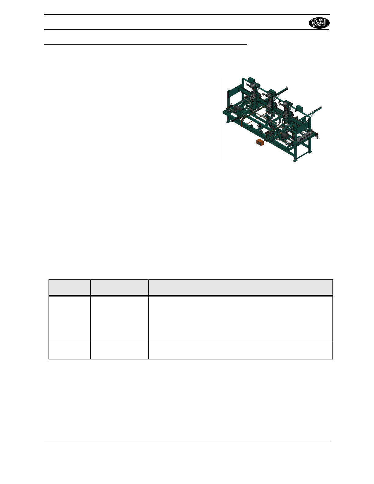
Overview of the 777
KVAL's Model 777 Flat Back Bi-Fold Machine is
designed to install flat back hinges on bi-fold doors. This
machine has a structural frame with four drill stations and
three hinge application stations. The basic machine
includes set up for 6’8” and 6’6” doors with hinge application units set on fixed centers.
Door width is adjustable from 8-3/4” to 24”. Thickness is
adjustable from 1-1/6” to 1-3/8”.
The 777 includes spring loaded wheels to support the panels as they are fed into the machine. Dual off-feed belts
are provided to move finished doors out of the machine,
so the next pair can be inserted.
Method of operation includes placing a pair of doors in machine and clamping them. Hinges can
be placed in machine during cycle operation so they are in position when machine is actuated.
Four drills move in to drill for pivot hardware. Hinges are manually placed and screws are automatically dispensed to attach hinges simultaneously. The machine then releases the doors and
another operator removes them manually from the off-feed side. Factory service trip included in
the price.
Overview of the 777
Available Options
TABLE 1-2. Options
Options Title Descriptions
Option A
Option E
8'0" Door Capacity To make machine adjustable to drill for the top and bottom pivot
holes in door up to 8'-0", and adjustment of the two outside screwdriver units to change center-toattach three hinges on doors up to 8’0" in length. Option also
includes upgrade to linear bearing slides and adjustment for end
drilling units.
Extra Screwdriver
ad
He
A fourth screwdriver head to add 8'0" door capability.
center distance of hinges to
KVAL 777 Operation/Service Manual
1-2
Overview of the 777
Operation/ Service Manual includes the following:
Chapter Description
Chapter 1 Introduction Descriptions of Machine Line and
Safety Information.
Chapter 2 Operation Interface Descriptions of how to power machine
line, and operator interface user
screens.
Chapter 3 Title Information about Maintenance of the
machines
Chapter 4 Troubleshooting Troubleshooing Tips
About this Manual
This manual contains operation information and service and maintenance information.
It includes identification of machine assemblies, power-up and power-down steps, and information about using the user interface.
The Troubleshooting and Maintenance sections are directed toward qualified service technicians only.
KVAL 777 Operation/Service Manual
1-3
vSafety First!
This machine is a powerful electro-mechanical motion control
system. You should test your motion system for safety under
all potential conditions. Failure to do so can result in dam-
age to equipment and/or serious injury to personnel.
Ensure that all employees who operate this machine
are aware of and adhere to all safety precautions
posted on the machine and are trained to operate this
machine in a safe manner.
Training
vSafety First!
Safety Sheet Sign-Off Sheet
At the end of this chapter, there is a safety sign-off sheet. It lists personnel and machine safety criteria to understand before operating the machine. It is highly recommended that personnel operating, working on a machine meet the criteria listed in this sheet. It is recommended the sheet be
signed and kept for records. See “Safety Sign-Off Sheet” on page 1-16.
Safety Terminology of Labels
In addition to the nameplate, KVAL machines may have other warning labels or decals that provide safety information to operators. Safety labels should be clearly visible to the operator and
must be replaced if missing, damaged, or illegible.
There are three types of warning labels or decals:
• DANGER means if the danger is not avoided, it will cause death or serious injury.
• WARNING means if the warning is not heeded, it can cause death or serious
injury.
• CAUTION means if the precaution is not taken, it may cause minor or moderate
injury.
Safety Guidelines
In addition to the caution and warning labels affixed to this machine, follow the guidelines below
to help ensure the safety of equipment and personnel.
KVAL 777 Operation/Service Manual
1-4
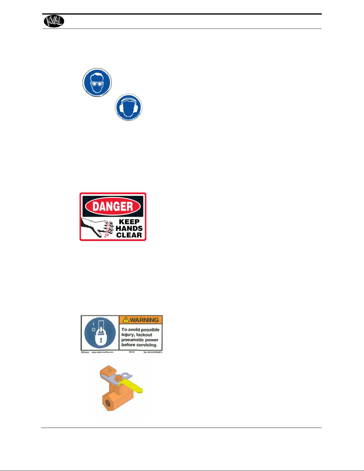
Never operate the machine without proper eye and
ear protection.
Protective Gear
• Never reach hands beyond safety cage. Servo
motors can unexpectedly move quickly.
• Never clear screws or hinges out of the machine
while it is running.
• Never reach into the router area to retrieve a
hinge. The router may still be running down
after shut down.
• Never perform any maintenance unless machine
is at zero state.
• Never clean the machine while it is running.
• Never walk away from the machine while it is
running.
When the Machine is ON
The compressed air system connected to this
machine should have a three-way air valve
for shut-off and pressure relief.
All cylinders on machine are under high
pressure and can be very dangerous when
activated. Before performing any maintenance or repairs on this machine turn off the
main air disconnect. Lockout and tagout
this connection.
See “Lockout Tagout Procedure” on
page 1-9.
Compressed Air
vSafety First!
KVAL 777 Operation/Service Manual
1-5
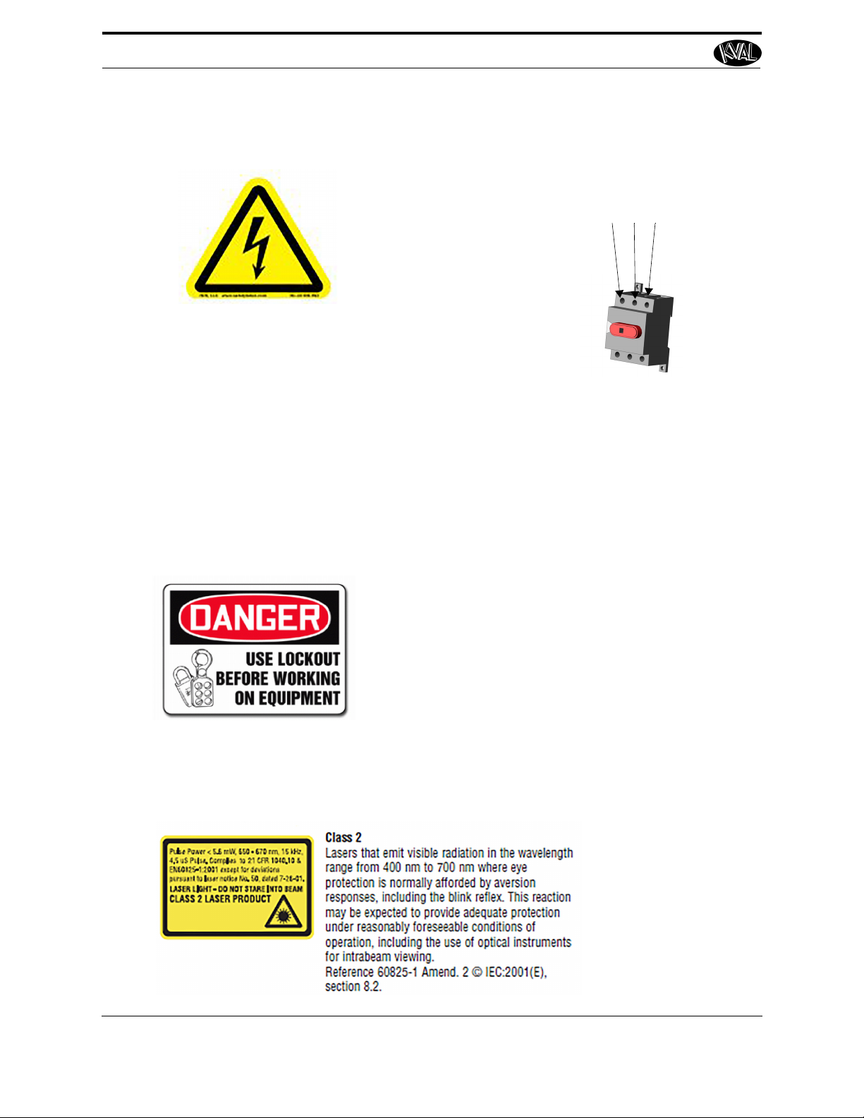
Electrical circuitry on this
machine is protected by an
approved lockable disconnect
circuit. In addition to this equipment, you must install an
approved disconnect for the
electrical power supplying this
machine.
When opening the cabinet you must first turn off the
disconnect switch. When the cabinet door is open there
is still power on the top side of the disconnect switch.
Some machines are powered by more than one supply
located at different locations. Before performing any repairs or maintenance, lockout and tagout must be installed at all locations
All maintenance and repairs to electrical circuitry should only be performed by a qualified electrician.
Still has power
in OFF position
Electrical
Prior to performing any maintenance, repairs,
cleaning or when clearing jammed debris, you
must disconnect, tag out, or lock out the electrical
and air pressure systems. This should be done in
accordance with applicable state and/or federal
code requirements.
Before Conducting Maintenance
Laser Warnings
On some machines, laser indicators are used to set boundaries. Follow the
manufacturers safety precautions.
vSafety First!
KVAL 777 Operation/Service Manual
1-6
KVAL advises that you request an on-site state
safety review of your installation of this
machine. This is to ensure conformance to any
additional specific safety and health regulations which apply in your geographic area.
Compliance with Codes and Regulations
Other Hazard Control Action
Report a Hazard
Before You Report an Accident
If you believe any part or operation of this machine is in
violation of any health or safety regulation, STOP production. It is your responsibility to immediately protect
your employees against any such hazard.
Additional detailed safety guidelines are included in the
operating instructions of this manual. KVAL will be
pleased to review with you any questions you may have
regarding the safe operation of this machine
Follow Your Company’s Safety Procedures
In addition to these safety guidelines. Your company
should have on-site and machine specific safety procedures to follow.
vSafety First!
KVAL 777 Operation/Service Manual
1-7
Lockout-Tagout Guidelines
Lockout-Tagout Guidelines
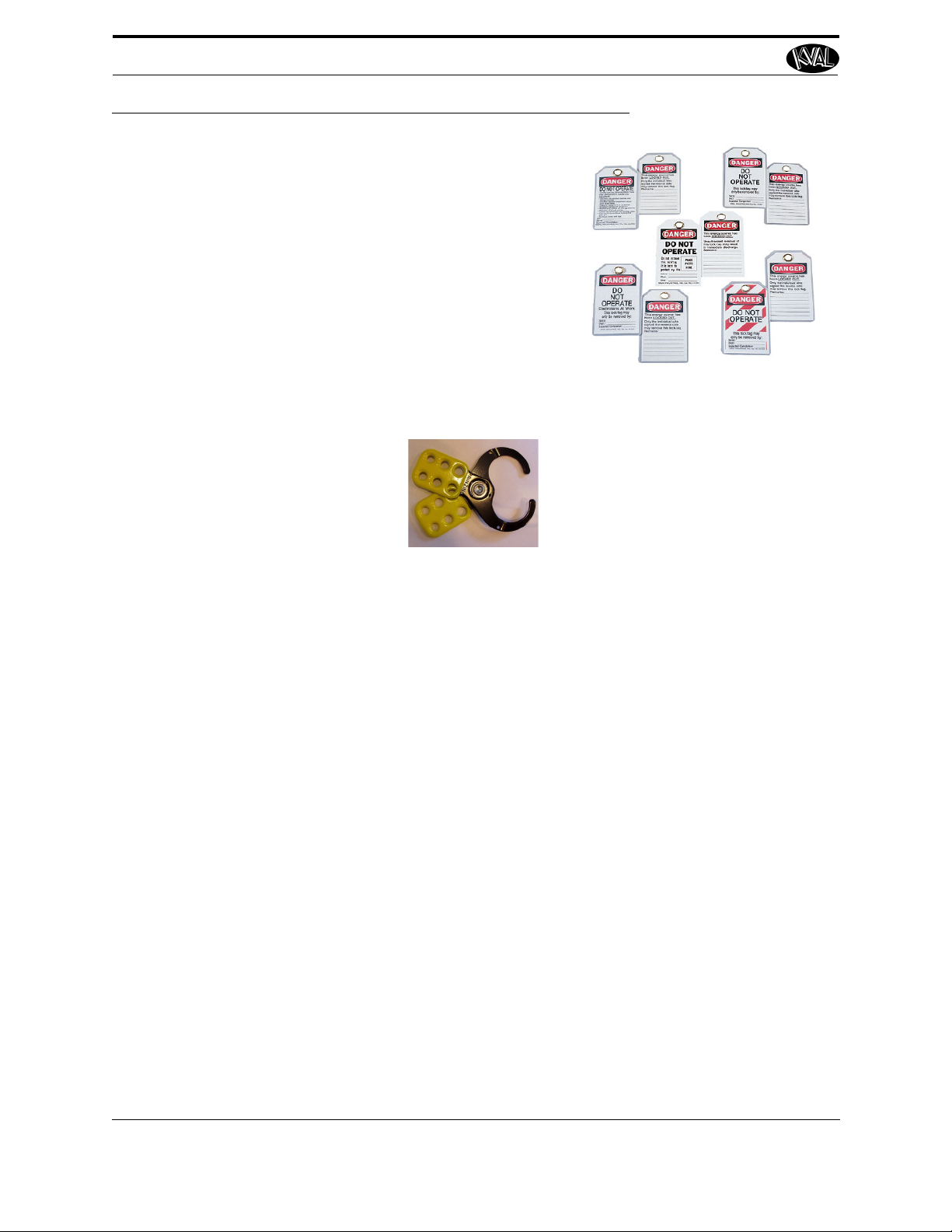
• Place a tag on all padlocks. On the tag, each
operator must put their own name and date.
(These locks are only to be removed by the
person who signs the tag)
• If more than one person is working on the
machine, each additional person places a lock
and tag on each disconnect.
• Only each operator may remove their own
lock and tag.
Important: When many people are all working
on the same machine you will need a multiple
lockout device, such as the one shown here.
Follow the P-R-O-P-E-R lockout rule of thumb.
P...... Process shutdown
R ...... Recognize energy type (electrical, pneumatic, mechanical, etc.)
O...... OFF! Shut off all power sources and isolating devices
P...... Place lock and tag
E...... ENERGY: Release stored energy to a zero-energy state
R ...... Recheck controls and test to ensure they are in the “OFF” state
KVAL 777 Operation/Service Manual
1-8
Lockout Tagout Procedure
1. Evaluate the equipment to fully understand all energy sources (multiple electrical
supplies, air supply and pressure, spring tension, weight shifts, etc.).
2. Inform all affected personnel of the eminent shutdown, and the duration of the
shutdown.
3. Obtain locks, keys, and tags from your employer’s lockout center.
4. Turn off machine. See Chapter 2 for power down and power up procedures.
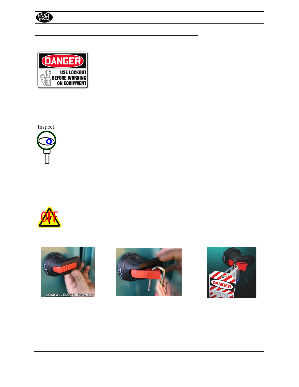
5. Turn the disconnect switches on ALL electrical and frequency panels to the OFF
position. Then push the red tab to pop it out. Place a padlock through the hole.
Place your tag on the padlock, as per the tagout guidelines below. (see illustration
below).
Note: When multiple people are working on the machine, each person needs to
have a lock on the handle in the extra holes provided.
Insert Lock into hole.
Turn Switch to the
OFF position
Lock and Tag out
This policy is required by OSHA regulation 1910.147 and Cal OSHA’ S
SB198 ruling of July 1991.
Use the following lockout procedure to secure this machine while it is
powered down. During a lockout, you disconnect all power and shut
off the air supply. Be sure to use the tagout guidelines noted below.
Pre-Steps Before Lockout Tagout
Lockout Tagout Procedure
Lockout Tagout Power
KVAL 777 Operation/Service Manual
1-9
Lockout Tagout Procedure
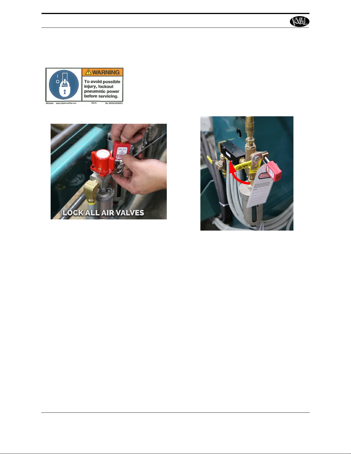
6. Turn all air valves to the OFF position and place a pad-
lock through the hole (see illustration below).
NOTE: Place your tag on the padlock, as per the
tagout guidelines.
Lockout Tagout Air Supply
Start Maintenance
7. Once the locks and tags are in place and all personnel are clear, attempt to operate
the machine to ensure equipment will not operate.
8. Maintenance or repairs may started.
Post Maintenance Steps
9. After maintenance is completed, the person performing the work must ensure all
tools, spare parts, test equipment, etc., are completely removed and that all guards
and safety devices are installed.
10. Before removing the locks and tags, the person who attached them shall inspect the
equipment to ensure that the machine will not be put in an unsafe condition when
re-energized.
11. The lock and tag can now be removed (only by the person(s) who placed them),
and the machine can be re-energized.
12. The tags must be destroyed and the locks and keys returned to the lockout center.
KVAL 777 Operation/Service Manual
1-10

Zero-Energy to Start-Up
Zero-Energy to Start-Up
Starting the equipment properly is just as important as the lockout/tagout guidelines in terms of
safety.
Start-up Guidelines
The following guidelines below should be followed to start the equipment.
Inspect
The equipment must be inspected for proper adjustment before starting equipment.
Clean Up
All materials and debris must be cleaned up. Any combustible materials or old parts
used during repairs must be cleaned up and/or properly disposed of.
Replace Guards
Replace all equipment guards. If part of equipment cannot be properly adjusted after
start-up with guard on, contact the KVAL Service team. See “Getting Help from
KVAL” on page 1-13.
Check Controls
Confirm that all switches are in the “OFF” position. Please be advised that some components of the machine may start automatically when energy is restored.
Remove Locks
Each operator must remove his or her own lock and tag. This will ensure that all operators are in a safe place when the equipment is started.
Perform Visual Checks
If the equipment is too large to see all around it, station personnel around the area and
sound the personnel alarm before starting the equipment. If your operation is more
complex, your company’s comprehensive safety procedure may involve additional
steps. You will need to ask your supervisor about these procedures. The company’s
lockout procedure should be posted at each machine. On larger or long-term maintenance or installation projects, the company’s procedures must be explained to all new
operators and a copy of the company’s procedures should be posted on-site for the
duration of the work.
The Company’s procedures should also include provisions for safely handling shift
changes and changes in operators or new operators.Comprehensive lockout/tagout
may use a gang box or other system to ensure that locks are secure and not removed
without authorization.
KVAL 777 Operation/Service Manual
1-11

Zero-Energy to Start-Up
Remember, lockout/tagout procedures work because you are the only one with the key
to your lock. Proper lockout/tagout can save lives, limbs, and money. Help make your
work environment safe for you and your fellow workers. Be sure to follow the P-R-OP-E-R lockout/tagout procedures, and that those around you do also.
Close the Cage Gate
Verify all cage gates are securely closed. Ensure all safety protocols are in effect.
KVAL 777 Operation/Service Manual
1-12
Getting Help from KVAL
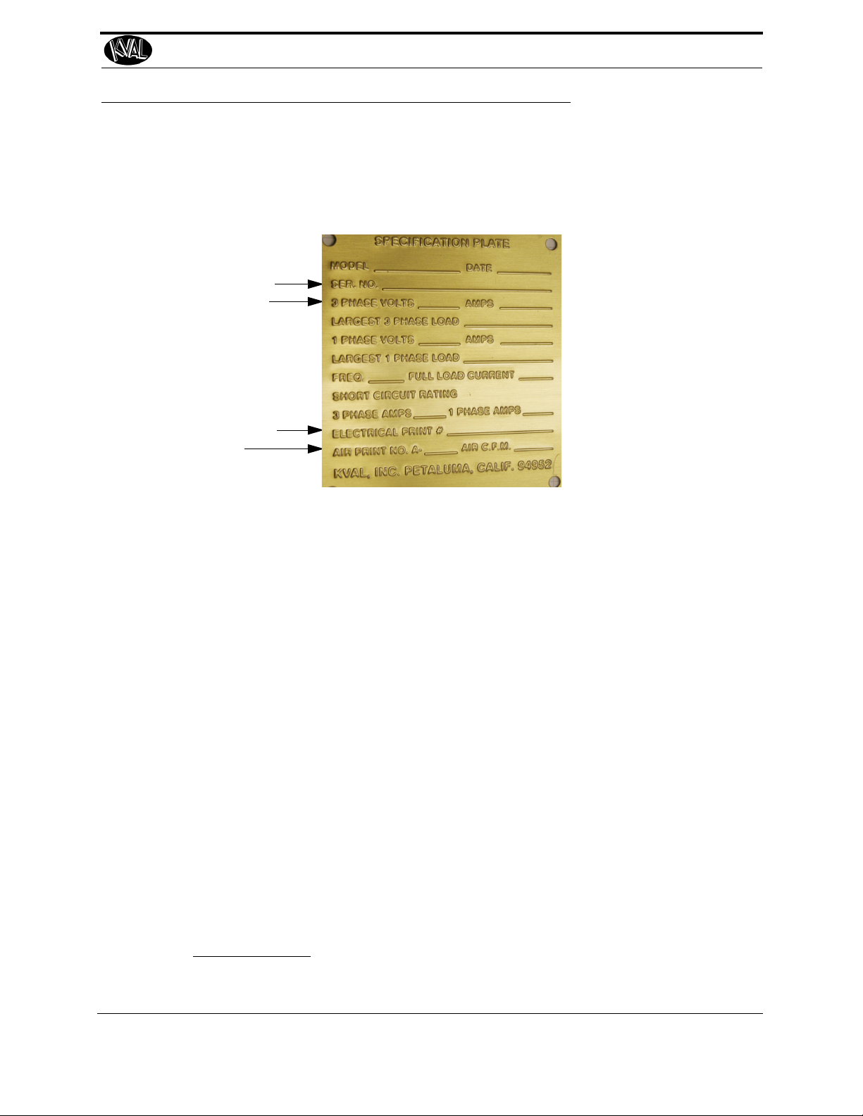
Serial Number
3 phase volts
Electrical Print
Air Print
Getting Help from KVAL
Before you seek help, first try the troubleshooting procedures. Follow the procedures below.
If you are unable to resolve the problem:
1. Locate the machine’s Specification Plate and record the serial number, 3 phase
volts, electrical print number, and air print number.
2. Contact our customer support team:
• In the U.S and Canada, call (800) 553-5825 or fax (707) 762-0485
• Outside the U.S. and Canada, call (707) 762-7367 or fax (707) 762-0485
• Email address is service@kvalinc.com
• Hours:
6:00 AM to 4:00 PM Pacific Standard Time, Monday through Thursday
6:30 AM to 1:30 PM Pacific Standard Time, Friday
On-Line Help
On machines with a Beckhoff® PLC and an internet connection, our service team are able to connect, run, and troubleshoot your machine. Ask about this procedure when calling are service team
Product Return Procedure
If you’ve contacted Kval for help and it is determined that a return is necessary, use the procedure
below to return the machine or part.
Note: Non-Warranty returns are subject to a 15% restocking charge.
1. Obtain the packing slip and/or invoice numbers of the defective unit, and secure a
purchase order number to cover repair costs in the event the unit is determined to be
out of warranty.
2. Reason for return: Before you return the unit, have someone from your organization
with a technical understanding of the machine and its application include answers to
the following questions:
KVAL 777 Operation/Service Manual
1-13

Getting Help from KVAL
• What is the extent of the failure/reason for return? What are the relevant error messages or error codes?
• How long did it operate?
• Did any other items fail at the same time?
• What was happening when the unit failed (e.g., installing the unit, cycling power,
starting other equipment, etc.)?
• How was the product configured (in detail)?
• Which, if any, cables were modified and how?
• With what equipment is the unit interfaced?
• What was the application?
• What was the system environment (temperature, spacing, contaminants, etc.)?
3. Call Kval customer support for a Return Material Authorization (RMA). When you
call:
• Have the packing slip or invoice numbers available.
• Have the documented reason for return available.
4. Send the merchandise back to Kval.
• Make sure the item(s) you are returning are securely packaged and well protected
from shipping damage
• Include the packing slip or invoice numbers.
• Include the documented reason for return.
• Include the RMA number with the parts package.
KVAL 777 Operation/Service Manual
1-14

Getting Help from KVAL
Page Intentionally Left Blank
KVAL 777 Operation/Service Manual
1-15

Safety Sign-Off Sheet
Safety Sign-Off Sheet
Machine Model Number:_____________________________
A Note to the Operator
This machine can help you be highly productive only if you understand how to use it properly and
follow the safe operating practices described in this document and the machine’s manual. If you
do not understand the machine’s proper operation or ignore the safe operating practices, this
machine can hurt or kill you. It’s in your best interest to safely and properly operate this machine.
Personnel Safety Concerns:
• I have been properly trained in the operation of this machine.
• I will always wear ear protection when operating this machine.
• I will always wear eye protection when operating this machine.
• I will never wear loose clothing or gloves when operating this machine.
• I will watch out for other people. Make sure everyone is clear of this machine
before operation.
• I will always follow my company’s safety procedures. I have read and understand
these guidelines.
Machine Safety Concerns:
• I have been given a tour of the machine and understand all the safety labels, E-
Stops and the actions to take in case of an emergency.
• I will make sure all guards are in place before operation
• I will turn off the compressed air, before loading hardware (staples, screws, etc)
• I will turn off the electrical power, for setup
• If the machine should operate in an unexpected manner stop production I will
immediately and notify a manager, a supervisor, or a qualified service technician.
I have read and understand this document and agree to operate this machine in a safe manner as described above.
Employee
Name (print):___________________ Signature: __________________ Date:____/____/
____
Supervisor/Safety Officer/Trainer
Name (print):__________________Signature: __________________ Date:____/____/___
Note: It is recommended you make a copy of this sheet for new operators. If a copy is needed, you may
download a PDF at the KVAL website (http://www.kvalinc.com). You may also contact our
Service Department at (800) 553-5825 or email at service@kvalinc.com.
KVAL 777 Operation/Service Manual
1-16
CHAPTER 2 Operation of the 777
The content is geared to help operators understand the basic operation of the KVAL 777 Flat Back
Bi-Fold Machine.
Chapter 2 at a Glance
Section Name Summary Page
Kval 777 Process
Summary
Powering Operations
Quick Start
Set the Width to the
Door
Adjust for the Length
of Door
Tour of the Machine
Controls
Illustrated summary of the operation of the machine page 2-2
Descriptions of power up, power down, homing,
and emergen
Steps to process a door. page 2-7
How to set the machine to match the width of a
.
door
How to set the machine to match the length of a
.
door
Descriptions of the main assemblies on the
hine.
mac
Descriptions of the controls of the machine. page 2-20
cy stops
page 2-3
page 2-9
page 2-13
page 2-17
KVAL 777 Operation/Service Manual
2-1
Kval 777 Process Summary
Turn Powe r
ON
Pull Out
Control Transformer
Push in Start Machine
Pre Set
a) Load Doors
b) Set Width Buttons
a) Load Hinges
b) Push the Hinges Loaded Button
Push Both Start
Sequence Buttons
Sequence Completed
Kval 777 Process Summary
KVAL 777 Operation/Service Manual
2-2
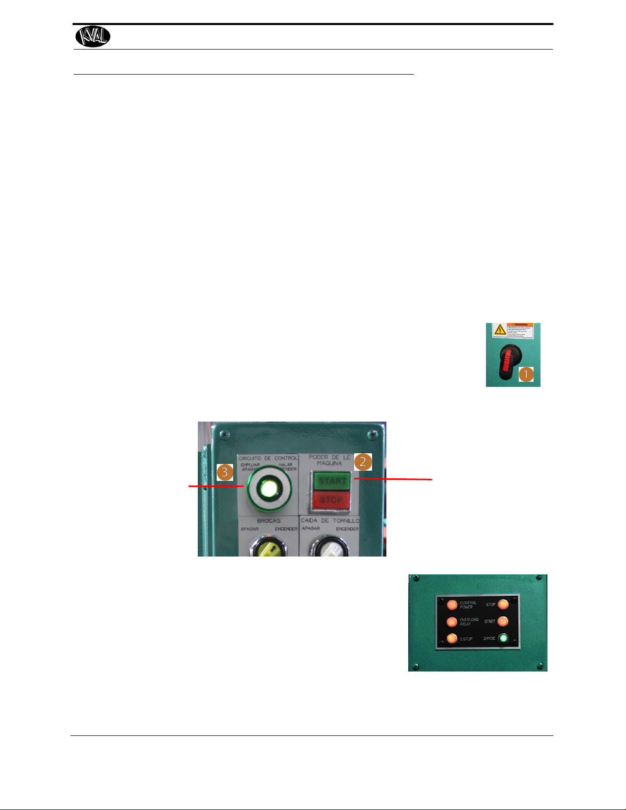
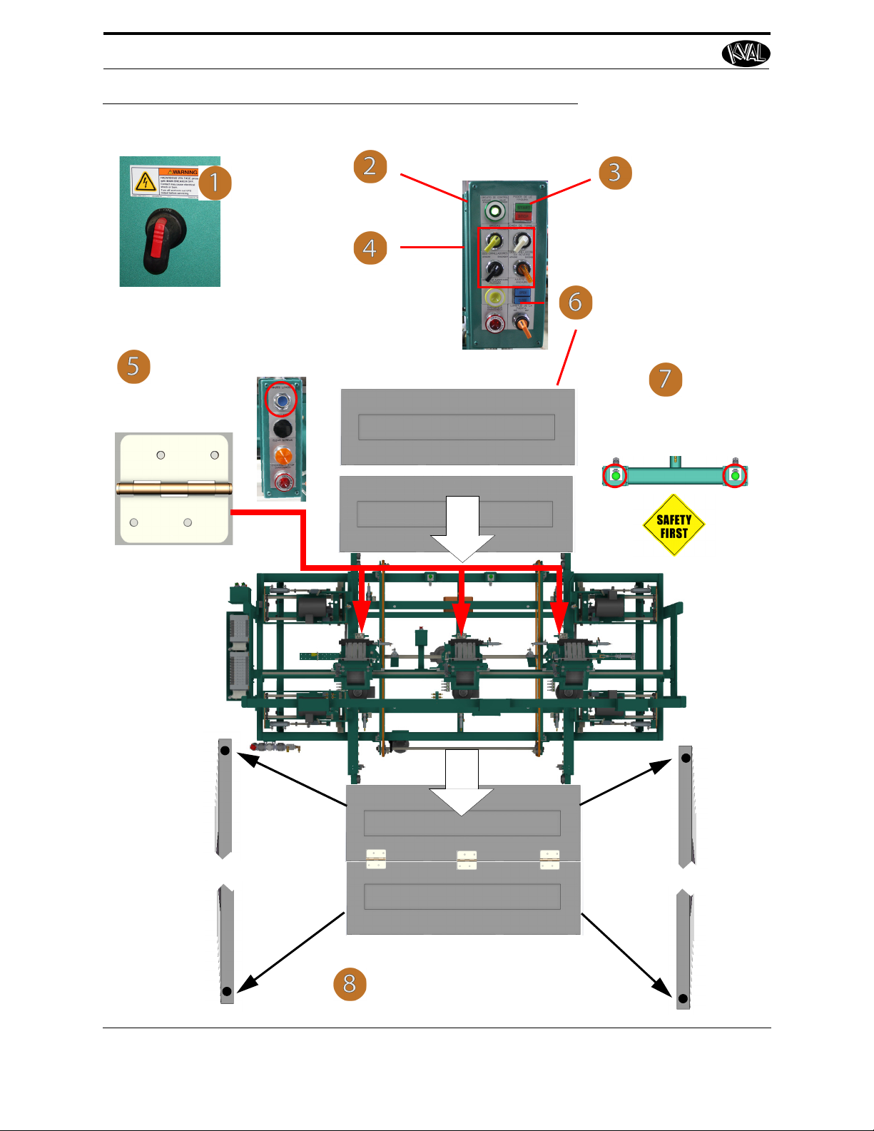
Powering Operations for the 777
1. Make sure the Electrical Disconnect the electrical cabinet is turned to
the ON position.
2. Pull out the green Control Transformer switch to the ON position.
3. Push the green Start Machine button to “boot up” the machine.
Control Transformer
Pull to ON
Press Start
4. All lights on the status light panel on the electrical
box should be illuminated. See “Description of the
Six Light Panel” on page 2-23
Note: If a status light does not turn on during the
power up process, see the Troubleshooting
Chapter in this manual.
Powering Operations for the 777
This section describes how to power up and to power down the KVAL777.
Powering up the system includes:
• Applying power to the entire system
• Starting the Control Transformer Circuit
Powering down the system includes:
• Shutting down the control power
• Removing power from the entire system
How to Power Up the 777
Ensure factory air is applied to machine and main air supply is turned on.
Check that all E-Stop buttons are out and safety gate door s are closed.
.
KVAL 777 Operation/Service Manual
2-3
Powering Operations for the 777
1. Push the Stop Button.
2. Switch the green Control Transformer
switch to the OFF position.
3. KVAL also recommends that
you turn the Disconnect
Switch
on the electrical cabinet to OFF; this helps reduce
possible damage resulting
from power surges from electrical storms.
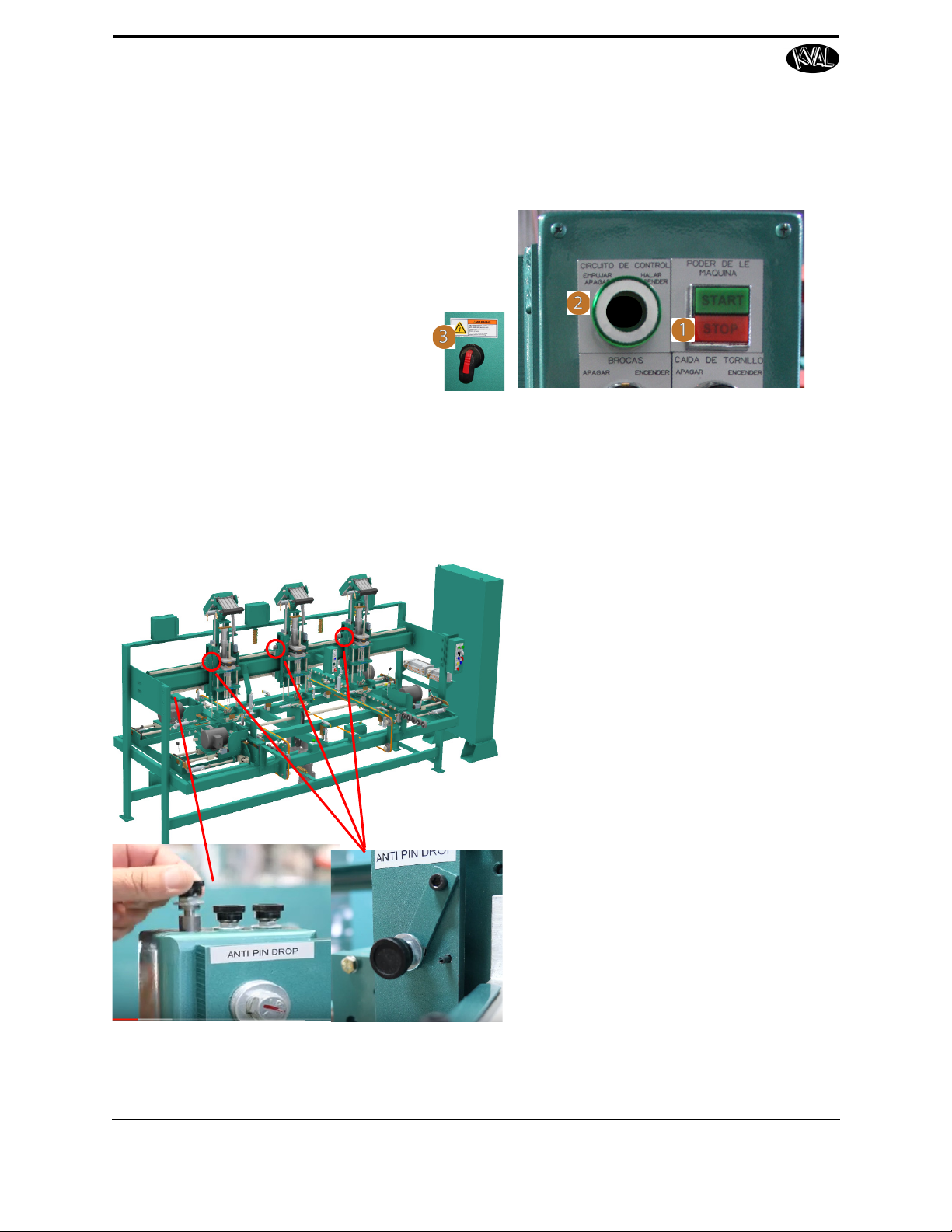
End of Shift
1. Keep air on.
2. Remove pins from staging area at the
end of the machine.
3. Insert pins into each location. (near
the side of each head.)
4. Flip the locking hook over the pins
for each Head
5. Turn off air.
Beginning of Shift
1. Turn air on. Wait a few minutes for
air to be applied to heads.
2. Flip lock hook off the pin.
3. Remove the pins.
4. Return pins to the storage point.
5. Start door processing.
How to Power Down the 777
Reverse the steps in the “How to Power Up the 777” on page 2-3.
Stabilizing Heads at the End of Shift
At the end of the shift, the Heads will slowly descend without air applied. Before that occurs
insert the pins to keep the Heads upright.
KVAL 777 Operation/Service Manual
2-4
Powering Operations for the 777
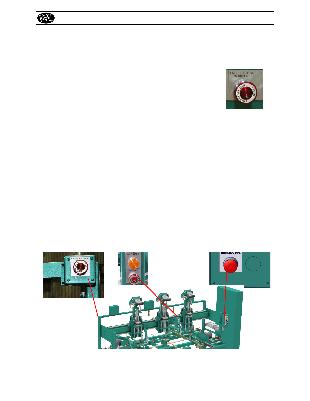
Emergency Shutdown and Recovery
Important: Learn all safety precautionary controls on the machine.
Depending on the model of machine, there are emergency shutdown (EStop) switches located at key points around the machine.
The E-Stop switches are to be used when the machine is out of control
or is about to damage personnel or equipment.
When an E-Stop switch is activated, high voltage power is cut to the
machine. The motors will stop, but power to the PLC and the Operator
Station Screen will remain on.
To Resume Normal Operation after an E-Stop
If an E-Stop is activated, use the following procedure to recover, after the cause of the emergency
stop is resolved:
1. De-activate the E-Stop switch by pulling it out.
2. Push the START MACHINE button on the operator's station
3. Other Safety Controls
Other safety controls can include:
• Gate Latches: Sensors are located on the gates surrounding the machine. If a gate
is opened the machine will shut down.
• Safety Curtain: This is similar to the Laser Safety Scanners. This creates an invisible curtain on all entrances.
Typical E-Stop Locations
FIGURE 2- 1. Locations of E-Stops
KVAL 777 Operation/Service Manual
2-5
 Loading...