


Innovation, Quality & Honesty
700-C System
Reference
Published: 3/8/18


Proprietary Notice
This document contains confidential and trade secret information, which is proprietary to Kval, Inc.
(“Kval”), and is protected by laws pertaining to such materials. This document, the information in this
document, and all rights thereto are the sole and exclusive property of Kval, are intended for use by customers and employees of Kval, and are not to be copied, used, or disclosed to anyone, in whole or in
part, without the express written permission of Kval. For authorization to copy this information, please
call Kval Customer Support at (800) 553-5825 or fax (707) 762-0485. Outside the U.S. and Canada, call
(707) 762-7367.
Copyright 2015 Kval Incorporated. All rights reserved.
KVAL 2012 and 700-C are trademarks of Kval, Incorporated.
All other products are trademarks or registered trademarks of their respective holders, all rights
reserved. Reference to these products is not intended to imply affiliation with or sponsorship of Kval
Incorporated.
Contacting KVAL
Customer Service: For further information about this manual or other Kval Incorporated products,
contact the Customer Support department
• http://www.kvalinc.com/customer_service.html (lists all the representatives, including email
addresses and phone numbers)
• Mailing address:
Customer Support department
Kval Incorporated
825 Petaluma Boulevard South
Petaluma, CA 94952
• Phone and Fax:
In the U.S and Canada, call (800) 553-5825 or fax (707) 762-0485
Outside the U.S. and Canada, call (707) 762-7367 or fax (707) 762-0485
• Business hours:
Technical Support: 4:00 AM to 4:30 PM Pacific Standard Time, Monday through Friday
Parts & Service Sales: 6:30 AM to 4:30 PM Pacific Standard Time, Monday through Friday
(Other sales related inquiries: http://www.kvalinc.com/contact_us.html)
• Email: service@kvalinc.com
Your Feedback is Welcome: To help us design products that make your job easier and your business
more successful, we'd like to gain your perspective about your user experience with our product - that
is, the manual, the machinery, the software, etc. What was easy or difficult to use or to learn? If you
could change something about the design, what would it be? Please email your comments and suggestions for improvement to userexperience@kvalinc.com. (NOTE: This is not a way to get customer support. For that, please refer to the Customer Service contact information above.) Thank you!
700-C a

b 700-C

Proprietary Notice ..................................................................................... .................... a
Contacting KVAL ....................................................................................... .................... a
CHAPTER 1
.................................................................................Introduction 1-1
Safety First!.........................................................................................................3
Lock Out Procedure.................................................................................. .................... 4
Lockout and Tagout Guidelines................................................................. .................... 5
Follow the P-R-O-P-E-R lockout rule of thumb. ....................................... .................... 5
Zero-Energy Start-Up..........................................................................................6
Zero-Energy State to Start-Up to Operating State..................................... .................... 6
Initial Set up ........................................................................................................9
Electrical Connections Overview...................... ... .... ... ... ... .... ... ... ... ... .... ... ........... ... .... ... 11
CHAPTER 2
.............................................................Operation of the 700-C 2-13
Machine Tour.......................................................................................................15
Quick Start...........................................................................................................17
Turning the 700-C On and Off.............................................................................21
Powering Up the 700-C.............................. ... ... ... .... ... ... .......................... ....... .... ... ... ... 21
Powering Down the 700-C...................................................................... .................... 21
Control Panel ......................................................................................................22
Main Control Panel.................................................................................. .................... 22
Remote Control Panel (Optional)............................................................ .................... 23
Width Adjust........................................... ....................................... ... .... ... .................... 24
Length Adjust (Option D).................. ... ... .... ... ... ... .................................... .................... 26
Touch Screen Interface.......................................................................................27
CHAPTER 3 ..............................................................................Maintenance 3-29
Maintenance Schedule........................................................................................30
Lubrication Schedule..........................................................................................31
Lubrication Requirements....................................................................... .................... 31
Grease Points ......................................................................................... .................... 33
CHAPTER 4
..................................................................Theory of Operation 4-37
I/O for Normal Operation .....................................................................................38
Clamps and Rollers (Feed System)...................................................................40
Tandem Cylinders .................................. .... ... ... ... .... ... ... ... .... ... ................ .............. ... ... 41
Wheel Assist Cylinder............................................................................. .................... 42
Operation ................................................................................................ .................... 42
Staple Guns.........................................................................................................43
Staple Gun Horizontal Positing ............................................................... .................... 44
CHAPTER 5
........................................................................ Troubleshooting 5-49
Troubleshooting the Air Cylinders.......................................................................50
KVAL 700-C Operation/Service Manual

Adjusting Cylinder Extension Speed:...................................................... .................... 51
Adjusting Cylinder Retraction Speed: ..................................................... .................... 51
Troubleshooting Electrical Problems...................................................................52
If the Power Stops During Normal Operation......................................... .................... 52
Troubleshooting with the Status Light Panel........................................... .................... 53
Troubleshooting Photo Detectors........................................................................57
Touch Screen Troubleshooting ...........................................................................59
Getting Help from Kval........................................................................................69
Product Return Procedure ...................................................................... .................... 69
Part Locations.....................................................................................................71
Control Panel .......................................................................................... .................... 77
700-C

CHAPTER 1 Introduction
The KVAL 700-C Frame Assembly Machine is generally used in-line with the Commander or 990
Series of machines.
The operation includes placing the strike jamb and header into the machine and clamping into place.
The door, with hinge jamb installed, is then moved into position, gently lowered into place, and then
securely clamped into position. A foot pedal activates the staple guns, which move vertically to attach
the jambs to the header. The door is then raised and rolled out of the machine to the next station to the
packaging station.
The 700-C is adjustable for doors from 18" to 4', wide with a standard length capacity of 6'8" or an
optional capacity for 7'0" and 8'0" doors. The 700-C can have up to four staple guns moun ted on four
corner brackets. Staple guns are not included.
SPECIFICATIONS
Footprint Size: 10' x 6'
Crated Dimensions: 120"L x 80"W x 53"H
Shipping Weight: 1,200 lbs.
{UL} Electrical panel is built according to Underwriter's Laboratories specifications and the UL label is
applied.
Prices FOB KVAL Plant in Petaluma, CA.
700-C 1

Introduction
2 700-C
Safety First!
The compressed air system connected to this machine should have a three-way air
valve for shut-off and pressure relief. The air supply line providing the pressure to this
machine also has a three-way air valve. All cylinders on the machine
are under high pressure and can be very dangerous when activated.
Before performing any maintenance or repairs on the machine, turn the
main air disconnect off. Lock-out and tag-out this connection.
Still has power
in OFF position
Safety First!
The 700-C is a powerful electro-mechanical motion control system. You should test your motion system
for safety under all potential conditions. Failure to do so can result in damage to equipment and/or serious injury to personnel.
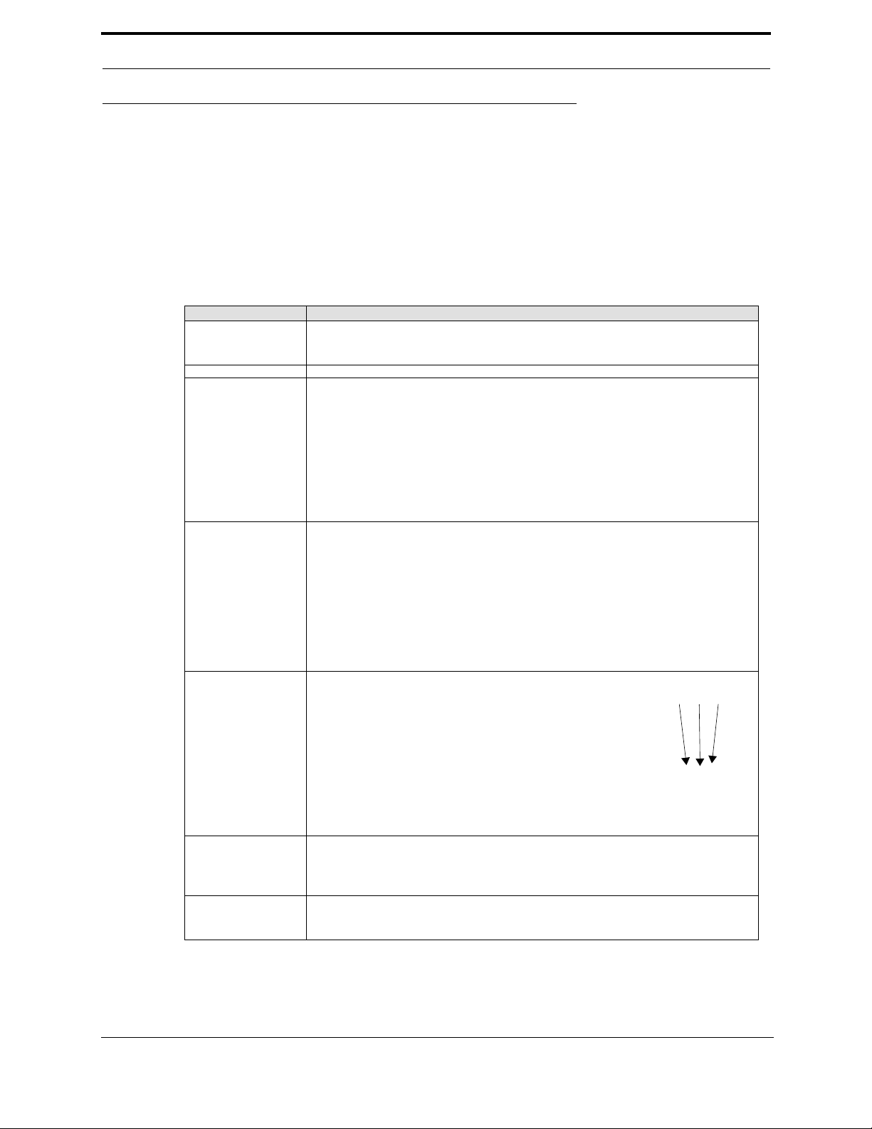
Safety Guidelines
In addition to the caution and warning labels affixed to the 700-C system, follow the guidelines below
to help ensure the safety of equipment and personnel.
Guideline Description
Safety Training Ensure that all employees who operate this machine are aware of and adhere to all
Protective Gear Never operate the machine without proper eye and ear protection.
Entering the Safety
Cage
Compressed Air .
safety precautions posted on the machine and are trained to operate thi s ma chine in a
safe manner.
When the machine is on:
• Never reach hands beyond safety cage. If the machine has servo motors
can unexpectedly move quickly and out of control.
• Do not clear slugs out of the machine while it is running.
• Never perform any maintenance while machine is running.
• Never clean the machine while it is running.
• Never walk away from the machine while it is running.
Electrical Electrical circuitry on this machine is protected by an
approved lockable disconnect circuit. In addition to this equipment, you must install an approved disconnect for the electrical power supplying this machine.
When opening the cabinet you must first turn off the disconnect switch. When the cabinet door is open there is still power
on the top side of the disconnect switch. All maintenance and
repairs to electrical circuitry should only be performed by a
qualified electrician.
Before Conducting
Maintenance
Compliance with
Codes and Regulations
700-C 3
Prior to performing any maintenance, repairs, cleaning or when clearing jammed
debris, you must disconnect, tag-out and lock-out the electrical and air pressure systems. This should be done in accordance with the state and/or federal code requirements.
KVAL Inc. advises that you request an on-site state safety review of your installation
of this machine. This is to ensure conformance to any additional specific safety and
health regulations which apply in your geographic area.

Other Hazard Control
When multiple people are
working on the machine, each
person needs to have a lock on
the handle in the extra holes
provided.
Action
Lock Out Procedure
This policy is required by OSHA regulation 1910.147 and Cal OSHA’S SB198 ruling of July 1991.
Use the following lockout procedure to secure the 700-C while it is powered down. During a locko ut,
disconnect all power and shut off the air supply. Be sure to use the tag-out guidelines noted below.
To lock out the 700-C
1. Assess the equipment to fully understand all energy sources (multiple electrical supplies, air supply
and pressure, spring tension, weight shifts, etc.).
2. Inform all affected personnel of the eminent shutdown, and the duration of the shutdown.
3. Obtain locks, keys, and tags from your employer’s lockout center.
4. Disconnect power.
NOTE:Always lock out electrical disconnects on both electrical cabinets
a. Turn the disconnect switches on the main electrical panel to the OFF position. Then pull out
the red tab and place a padlock through the hole. Place your tag on the padlock, as per the tagout guidelines below. (see picture below).
If you believe any part or operation of this machine is in violation of any health or
safety regulation, it is your responsibility to immediately protect your employees
against any such hazard and bring the matte r to our attention for review and correction,
if deemed advisable.
Additional detailed safety guidelines are included in the operating instructions of this
manual. KVAL will be pleased to review with you any questions you may have regarding the safe operation of this machine.
b. Turn the disconnect switch on the lar ger high-frequency panel to the OFF position. Then pull
out the red tab and place a padlock through the hole. Place your tag on the padlock, as per the
tag-out guidelines below
4 700-C

Safety First!
5. Turn the main air valve to the OFF position and place a
padlock through the hole (see illustration).
NOTE: Place your tag on the padlock, as per the tag-out
guidelines below.
6. Insure the machine will not operate.
7. When maintenance or repairs are completed, the person
who performed the work must ensure all tools, spare parts,
test equipment, etc., are completely removed and that all
guards and safety devices are installed.
8. Before removing the locks and tags, the person who
attached them shall inspect the equipment to ensure that
the machine will not be put into an unsafe condition when
re-energized.
9. The lock and tag can now be removed (only by the person(s) who placed them), and the machine can
be re-energized.
10. The tags must be destroyed and the locks and keys returned to the lockout center.
Lockout and Tagout Guidelines
• Place a tag on all padlocks. On the tags, include your
name and date.
• These locks are only to be removed by the person
whose name is on the tag.
• If more than one person is working on the machine,
then each additional person places a lock and tag on
each disconnect.
• You may only remove your own lock and tag.
NOTE: When many people are working on the same
machine, a multiple lockout device is necessary.
Follow the P-R-O-P-E-R lockout rule of thumb.
P...... Process shutdown
R ...... Recognize energy type (electrical, pneumatic, mechanical, etc.)
O...... OFF! Shut off all power sources and isolating devices
P...... Place lock and tag
E...... ENERGY: Release stored energy to establish, insure and achieve a zero-energy state
R ...... Re-check controls and test to ensure they are in the “OFF” position
700-C 5

Zero-Energy Start-Up
Zero-Energy State to Start-Up to Operating State
Starting the equipment properly is just as important as the lock-out/tag-out procedure in terms of safety.
Start-up
• Inspect
• Clean up
• Replace guards
• Check controls
• Remove locks
• Perform visual checks
Inspect
When work is finished, the equipment must be inspected for proper adjustment before starting equipment.
Clean Up
All materials and debris must be cleaned up. Any combustible materials or old parts used during repairs
must be cleaned up and/or properly disposed of.
Replace Guards
Replace all equipment guards. If part of equipment cannot be properly adjusted after start-up with guard
on, leave only that guard off.
Check Controls
Confirm that all switches are in the “OFF” position. In some cases, the machine can start automatically
when energy is restored.
Remove Locks
Each person must remove his or her own lock and tag. This will ensure operators are in a safe place
when the equipment is started.
Perform Visual Checks
If the equipment is too large to see all around it, station personnel around the area and sound the personnel alarm before starting the equipment. If your operation is more complex, having many pieces of
equipment and a lot of people, a comprehensive lock-out/tag-out procedure may involve additi onal
steps. You will need to ask your supervisor about these procedures. A specific lock-out procedure may
be posted at each machine. On larger or long-term maintenance or installation projects, the procedures
should be explained to all participants and a copy of the procedures should be posted on-site for the
duration of the work. Provisions which ensure protection during shift changes when contractor or outside help is used must also comply with the lock-out/tag-out procedures. Comprehensive lock-out/tag-
6 700-C

Zero-Energy Start-Up
out may use a gang box or other system to ensure that locks are secure and not removed without authorization.
Remember, lock-out/tag-out procedures work because you are the only one with the key to your lock.
Proper lock-out/tag-out can save lives, limbs, and money. Help make your work environment safe for
yourself and your fellow workers. Be sure to follow the P-R-OP-E-R lock-out/tag-out procedures, and
that those around you do also.
YOUR LIFE MAY DEPEND ON IT.
700-C 7

8 700-C

Initial Set up
Initial Set up
Y our new Kval machine arrives at your plant crated, banded, taped, with painted set collars on all shafts,
keeping all of the precision moving parts secure during shipping.
1. To protect against damaging the machine with the forklift, move the machine as close as possible to
the area where it will be stationed before removing it from the crate
2. Use caution when removing the machine from the crate. Any time the machine is lifted to remove the
skids, there is a chance that the machine could drop suddenly, which could damage the machine or
injure people near the machine.
3. Remove all painted set collars from the shafts. Almost every shaft on the machine has set collars to
secure the moveable assembly mounted to the shafts.
4. Remove any tape securing the various buttons, switches and knobs. Level your Kval machine by put-
ting metal shims underneath the corners of the base. Leave a clear shot from the bolt holes in the foot
pads to your shop floor.
5. Once the machine is level, anchor it to the floor so that it won't move across the floor during opera-
tion. Kval recommends a ½-inch Red Head, Trubolt anchor in each of the foot pads.
700-C 9
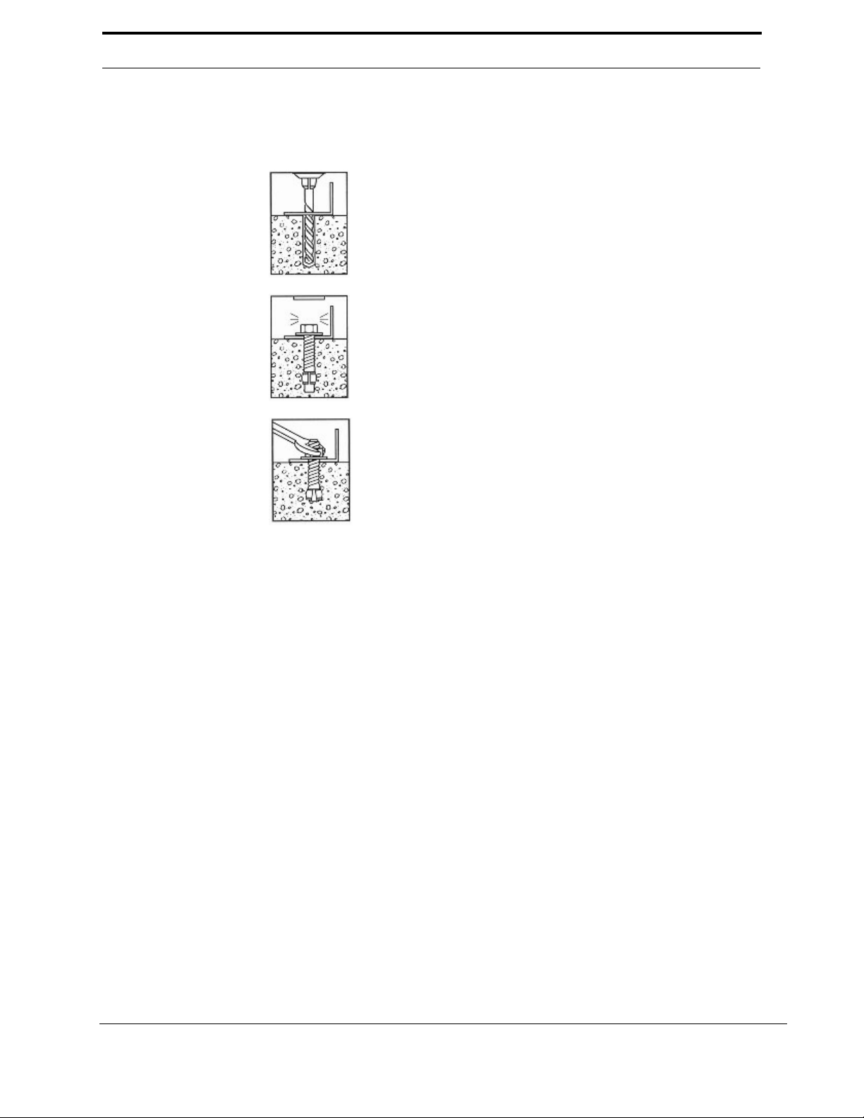
Trubolt Wedge Anchor
1.Drill a ½-inch hole, minimum of 6-inch depth. Clean hole.
NOTE: Kval recommends drilling completely through the slab. If in the
future the machine needs to be moved, remove the Red Head nut and
pound the bolt flush with the floor surface.
2.Assemble anchor with nut and washer so that the top of the nut is flush
with the top of the anchor. Drive anchor through material to be fastened so
that nut and washer are flush with surface material.
3.Expand anchor by tightening nut 3 to 5 turns (torque requirement 55 ft.
lbs. for a ½-inch Red Head Trubolt
INSTALLATION INSTRUCTIONS
10 700-C
Initial Set up
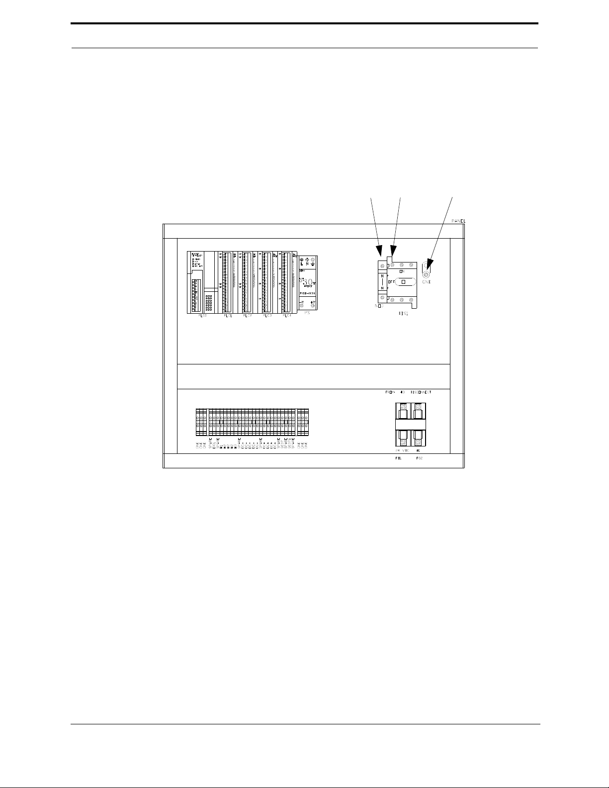
The main electrical power is connected to the disconnect,
located in the large electrical panel.
The 700-C requires 110 Volt AC. Typically this voltage is
pulled from the previous machine. Refer to the plant layout diagram from more information.
Neutral Hot Ground
110Volt AC
Electrical Connections Overview
700-C 11

12 700-C

CHAPTER 2 Operation of the 700-C
700-C 13

Operation of the 700-C
14 700-C

Machine Tour
Feed Direction
Infeed
End
Outfeed
End
Movable
Fence
Main
Control
Panel
Fixed
Fence
Right Hand
Movable Side
Gun
Left Hand
Movable Side
Gun
Right Hand
Fixed Side
Gun
Left Hand
Fixed Side
Gun
Touch
Screen
Machine Tour
700-C 15

16 700-C
Quick Start
CONTROL CIRCUIT
OFF ON
STAPLE SEQUENCE
0
1
2
3
4
5
6
7
RESET 700-C
JAMB TYPE
REG. SPLIT
ENABLE FIXED
SIDE GUNS
OFF ON
ENABLE MOVABLE
SIDE GUNS
OFF ON
FIRE GUNS
JAMB WIDTH JAMB WIDTH
WIDTH ADJUST
PUSH
CLAMP
PULL
RELEASE
FIRE SIDE NAILER
Door Length
6’ 8”
8’ 0”
SELECT
LOCAL REMOTE
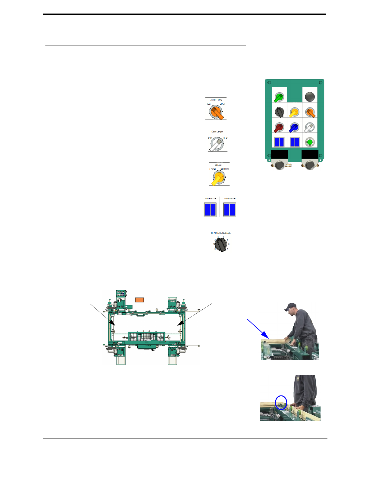
2. Select the Jamb Type. See “Main Control
Panel” on page 22.
3. Select Door Length (Optional). See “Main Con-
trol Panel” on page 22.
4. Select the Local or Remote control box
(Optional). See “Main Control Panel” on
page 22.
5. Select a Jamb Width. See “Control Panel” on
page 22.
6. Select a Staple Sequence. See “Control Panel” on
page 22.
Left hand door
Header location
Right hand door
Header location
Header Location
Left or Right Hand
10. Insert Strike Jamb and insure head and strike jamb corners meet
Quick Start
Set the door width and length before starting the process. See “Width Adjust” on page 24. See “Length Adjust
(Option D)” on page 26.
1. Power up the 700-C. See “Powering Up the 700-C” on page 21.
7. Insure the proper staple guns are enabled and staples are loaded. See “Control Panel” on page 22.
8. Adjust the machine for the desired door width. See “Width Adjust” on page 24.
9. Insert the jambs
.
700-C 17
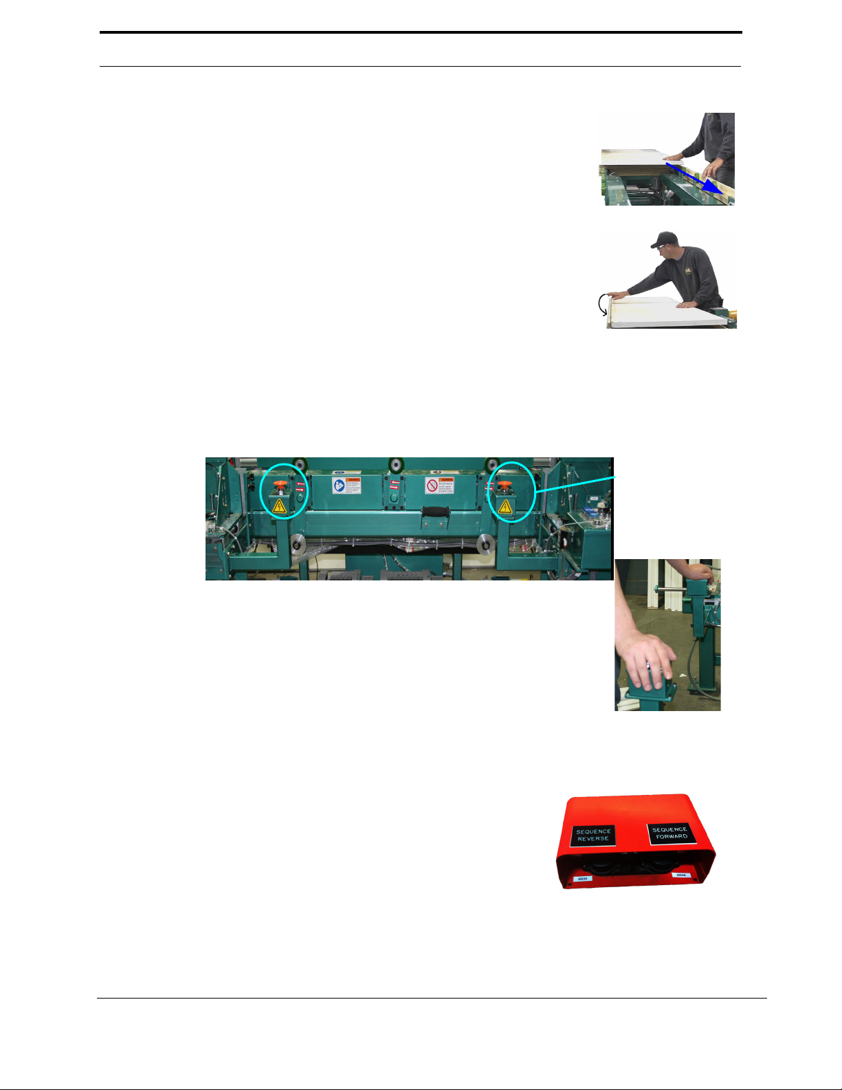
11. Pull in the door.
12. Swing the hinge jamb down.
13. Use the Foot Pedal to control the process. First Activate the Foot Pedal (Option).
14. Each press of the Sequence Forward operates the machine in a predetermined process. Press the
Sequence Reverse switch to go back 1 step to fix errors or recheck setup. Press the Sequence
Forward
to continue to where you left off.
• Push the
Sequence Forward foot switch (brings in movable
side staplers).
• Push the
Sequence Forward foot switch again (drops door to
lower position).
• Ensure the hinge jamb is in the correct position in relation to
the head jamb.
• Push the
Sequence Forward foot switch a third time (brings in the fixed side staple guns).
• Push the
Sequence Forward foot switch a fourth time (clamps the door).
NOTE:
Some 700-C machines have dual switches that must be activated to use the
Foot Pedals. The
switches are located next to the
Control Panel. If these switches are not installed bypass these
instructions and go to step 14
Press both switches to activate the Foot Pedal. Both switches must me
maintained to operate the Foot Pedal. If one or both switches are not
pressed, the foot pedal will not operate.
If a hand is taken of the switch during process, there is a 2 second delay
before the process can be resumed.
With both switches maintained, go to step 14 to continue using the Foot
Pedal
Dual Switches
18 700-C
Quick Start
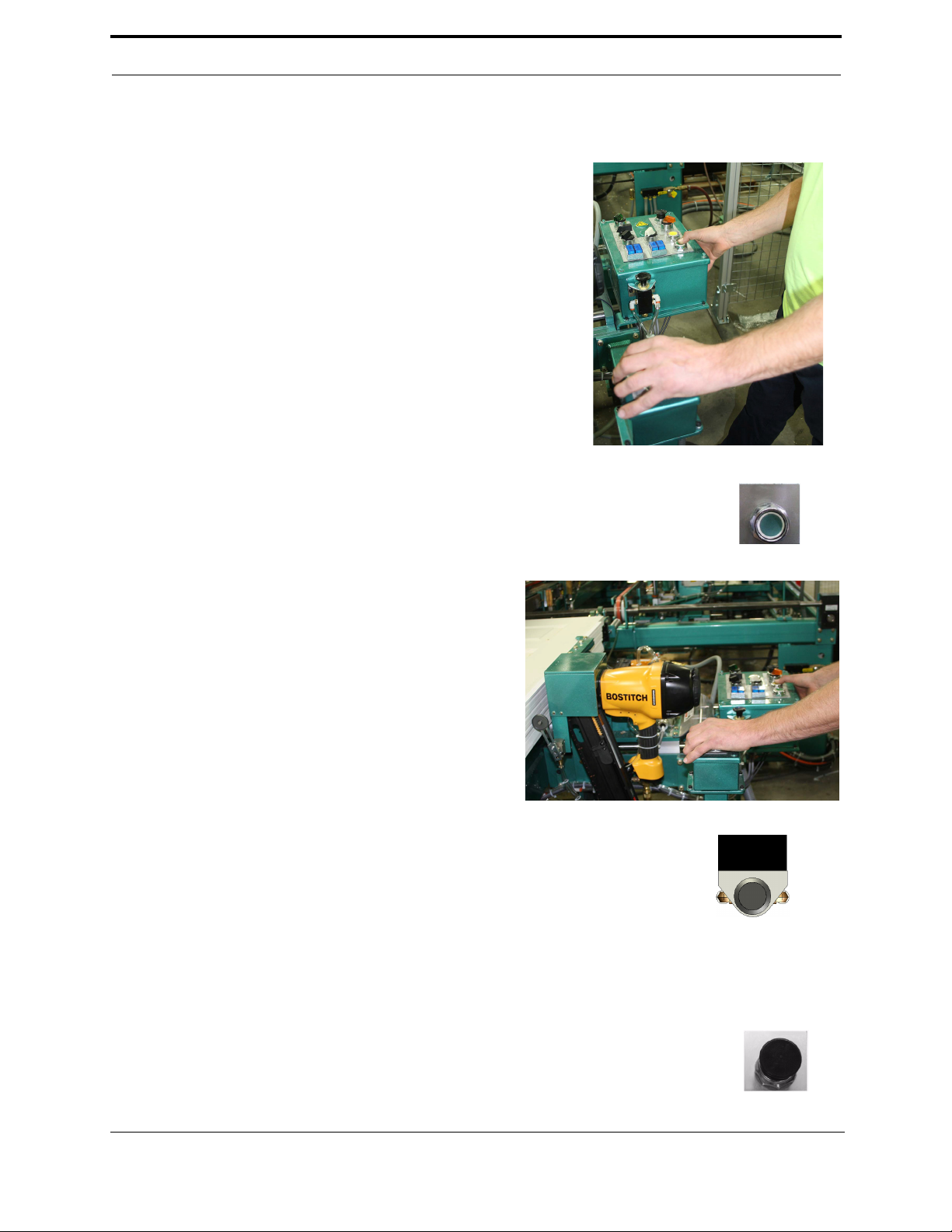
15. For 700-C machines that have dual switches, simultane-
ously hold the switch located next to the
Control Panel
and Press Fire Guns
Note: If a hand is taken of the switch during process, there is
a 2 second delay before the process can be resumed.
If these switches are not installed, bypass these instructions
and go to step 16
FIRE GUNS
16. Press Fire Guns (See “Control Panel” on page 22.)
Fire Side Nailer
17. For 700-C machines that have dual switches,
simultaneously hold the switch located next to
the
Control Panel and Fire Side Nailer
Note: If a hand is taken of the switch during pro-
cess, there is a 2 second delay before the process
can be resumed.
If these switches are not installed, bypass these
instructions and go to step 18
18. Press Fire Side Nailer (Optional) (See “Control Panel” on page 22.)
RESET
21. Press Reset. (Returns machine to start position) (See “Control Panel” on page 22.)
Firing Staple Guns and Nailer
19. Push the Sequence Forward foot switch (un-clamps door).
20. Outfeed door.
700-C 19

20 700-C
Turning the 700-C On and Off
POWER
RELAY
E-STOP
STOP
START
Turning the 700-C On and Off
Use the procedures below for powering up and powering down the 700-C.
Powering Up the 700-C
Powering up the system includes:
• Applying power to the entire system
• Starting the Control Circuit
To Power Up the 700-c
1. Make sure the electrical disconnect the electrical cabinet is turned to the ON position.
2. Turn the CONTROL TRANSFORMER switch located on the main control panel to the ON position.
It should light up.
3. All lights on the status light panel on the electrical box should be illuminated.
CONTROL
OVERLOAD
24VDC
Powering Down the 700-C
Powering down the system includes:
• Shutting down the control power
• Removing power from the entire system
To Power Down the 700-C
1. Turn the CONTROL TRANSFORMER switch to the OFF position. This kills power to the machine.
All status lights should be off.
2. Kval also recommends that you turn the disconnect switch on the electrical cabinet to OFF; this helps
reduce possible damage resulting from power surges from electrical storms.
700-C 21

CONTROL CIRCUIT
OFF ON
STAPLE SEQUENCE
0
1
2
3
4
5
6
7
RESET 700-C
JAMB TYPE
REG. SPLIT
ENABLE FIXED
SIDE GUNS
OFF ON
ENABLE MOVABLE
SIDE GUNS
OFF ON
FIRE GUNS
JAMB WIDTH JAMB WIDTH
WIDTH ADJUST
PUSH
CLAMP
FIRE SIDE NAILER
Door Length
6’ 8”
8’ 0”
SELECT
LOCAL REMOTE
PULL
RELEASE
Control Panel
Main Control Panel
Note: If the machine has the optional remote control panel, both the main and remote panel Movable
Side Gun switches must be in enable to enable the movable side staple guns.
• Door Length: Sets the machine up for 6’8” door length or a 8’0” length door.
• Jamb Width buttons: These four buttons set the machine up for the jamb width indicated on each button.
Note: Jamb width MUST be select for the machine to function.
• Fire Guns: Fires the enabled staple guns.
Note: Staple guns are enabled by the Enable Fixed Side Guns switch, the Enable Movable Side Guns
switch, the LS-14 and LS-15 limit switches (See “Fixed Fence - Inside view” on page 74. for limit
switch locations).
• Fire Side Nailer (Optional): Fires the side nailer guns.
• Width Adjust: Pulling this button releases the movable fence to adjust the fence for the disired door
width. See “Width Adjust” on page 24. for width adjust information.
• Control Circuit: Turns power on and off tho the
machine.
• Reset 700-C: Returns the machine to the first
sequence of operation.
• Staple Sequence: Selects one of seven user-programmed staple patterns. See “Programming” on
page 28. for staple programming instructions
Note: If Staple Sequence 0 is selected no staples will
be fired.
• Select (Optional): This switch between the Main and
Remote control panels. (See “Remote Control Panel
(Optional)” on page 23.)
• Jamb type: Sets the machine up for regular or split
jamb.
• Enable Fixed Side Gun: Enables the staple guns on
the fixed fence side of the machine.
Note: If the machine has the optional remote control
panel, both the main and remote panel Enable Fixed
Side Gun switches must be in enable to enable the
fixed side staple guns.
• Enable Movable side Guns: Enables the staple guns
on the movable fence side of the machine.
22 700-C

Control Panel
STAPLE SEQUENCE
0
1
2
3
4
5
6
7
RESET 700-C
ENABLE FIXED
GUSIDE GUNS
OFF ON
ENABLE MOVABLE
SIDE GUNS
OFF ON
FIRE GUNS
JAMB WIDTH JAMB WIDTH
WIDTH ADJUST
PUSH
CLAMP
PULL
RELEASE
FIRE SIDE NAILER
Remote Control Panel (Optional)
machine up for the jamb width indicated on each button.
Note: Jamb width MUST be select for the machine to function.
• Fire Guns: Fires the enabled staple guns.
Note: Staple guns are enabled by the Enable Fixed Side Guns switch, the Enable Movable Side Guns
switch, the LS-14 and LS-15 limit switches (See “Fixed Fence - Inside view” on page 74. for limit
switch locations).
• Width Adjust: Pulling this button releases the movable fence to adjust the fence for the desired door
width. See “Width Adjust” on page 24. for width adjust information.
• Fire Side Nailer (Optional): Fires the optional side nailer guns.
• Staple Sequence: Selects one of seven user-pro-
grammed staple patterns. See “Programming” on
page 28. for staple programming instructions
Note: If Staple Sequence 0 is selected no staples will
be fired.
• Reset 700-C: R3eturns the machine to the first
sequence of operation.
• Enable Fixed Side Gun: Enables the staple guns on
the fixed fence side of the machine.
Note: Both the main and remote panel Enable Fixed
Side Gun switches must be in enable to enable the
fixed side staple guns.
• Enable Movable side Guns: Enables the staple guns
on the movable fence side of the machine.
Note: Both the main and remote panel Movable Side
Gun switches must be in enable to enable the movable
side staple guns.
• Jamb Width buttons: These four buttons set the
700-C 23

Width Adjust
Collar
Bars
“Pickle”
Fork locations
Width Adjust
button
Measuring
Tape
Location
Movable
Fence
Thick Jamb
Spacer 1
Thick Jamb
Spacer 2
T-Handle
Inner Collar
Thick Jamb
Spacer
Collar bar
Bracket
Collar Bar
Travel
Outer Collar
Thick Jamb Thin Jamb
The following describes adjusting the 700-C to accommodate different door widths. The picture below
shows the location of the width adjust system components.
To adjust the width of the 700-C:
1. If necessary set the Thick Jamb spacers 1 and 2.
To adjust the Thick Jamb spacers:
a. Use the T-handle to loosen the inner collars for
Thick spacer.
b. Slide the outer collar up agents the collar bar
bracket for a narrow jamb. Or away from the collar
bar bracket to allow for the Thick Jamb spacer.
Thick Jamb spacer positions:
24 700-C
c. Put the Thick Jamb spacer in the disired position.
d. Push the inner collar up agents the collar bar
bracket and tighten the T-handle, securing the collar bar.
Use the above process for both Thick Jamb spacer
1 and Tick Jamb spacer 2.

Control Panel
Measuring Tape
Pickle Fork
(Shown in the retracted position)
Pickle Fork
(Shown in the extended position)
18” 20” 22” 24” 26” 28” 30” 32” 34” 36”
48”
Spares
42”
2. Pull up the width adjust button located on the main control panel or
the (optional) remote control panel. This will retract the pickle forks
freeing the movable fence for positing.
3. Slide the movable fence to the disired location indicated by the
measuring tape located on the main frame of the machine. This will
retract the pickle forks.
4. Push down the width adjust button. This will cause the pickle forks
to extend capturing a collar and locking the position of the movable
fence.
Note: The “pickle fork” must capture a collar for proper operation.
The Collar bar
The collar bar has factory positioned collars set for door widths of 18”, 20” 22”, 24”, 26”, 28”, 30”, 32”,
34”, 36”, 42”and 48”. There are two additional collars for user settable positions.
700-C 25

Length Adjust (Option D)
End Clamp set at 6’8”
Adjustment Pin
7’0” 8’0”
There are 2 adjustment end clamps at each end of
the machine. Adjust all 4 end clamps.
T o adjust the end clamps for 6’8”, 7’0”, or 8’0”
doors, pull the pins and move clamps to the appropriate length. Secure pin in the adjustment hole.
See the figure below.
The following describes adjusting the 700-C to accommodate different door lengths.
FIGURE 1. Adjustment End Clamps
26 700-C

Touch Screen Interface
Maintenance
See “Maintenance
Screen” on page 59.
Programing screens
See See “Programming”
on page 28. (below)
Touch Screen Interface
The following is an overview of the touchscreen functions for basic machine operation.
Main Screen
700-C 27

Programming
Program
Number
Programing
Buttons
1
2
3
4
5
6
7
8
9
10
11
12
13
14
15
16
17
18
19
20
21
22
23
24
25
26
27
3/4”
1”
1 1/4”
1 1/2”
1 3/4”
2”
2 1/4”
2 1/2”
2 3/4”
3”
3 1/4”
3 1/2”
3 3/4”
4”
4 1/4”
4 1/2”
4 3/4”
5”
5 1/2”
5 1/2”
5 3/4”
6”
6 1/4”
6 1/2”
6 3/4”
7”
7 1/4”
6
11
Programming Buttons
The programming buttons determine where staples will be fired into the jamb. For all programs a staple is fired approximately 1/2” below the top of the jamb in reference to how
the jamb is oriented in the 700-C. The programming buttons are used to toggle other staple
locations.
For example:
If staples where desired at 1/2”, 2” and 3 1/4”, programming buttons 6 and 11 would be
pushed.
• 1/2: A staple is always fired at this location.
• 2”: This location requires button 6 pressed.
• 3 1/4”: This location requires Button 11 pressed.
Note: All programming button locations have a tolerance of +/- 1/4”
28 700-C

CHAPTER 3 Maintenance
This chapter describes how to maintain the 700-C system. This chapter contains the following information:
• Maintenance schedule.......................page 30
• Lubrication requirements...................page 31
700-C 29

Maintenance
Maintenance Schedule
KVAL recommends the following maintenance schedule to ensure that the machine operates
properly. Refer to this section for steps to perform maintenance.
Daily Preventive Maintenance
Op Operation Description
Clean
Check
Clean
Check
Clean
Check
Check
Blow off dust from the entire machine.Wipe down the outside of the machine with a
clean dry cloth.
Check tooling for wear.
Wipe of f the photo eyes with a clean dry cloth, and check to ensure that all fastening nuts
are snug.
Check the air pressure to make sure it is set at 80 psi to100 psi.
Empty any Dust Collection Units.
Check for obstructed flow when excessive sawdust appears.
Check the air filter water trap. Empty if full.
Weekly Preventive Maintenance
Op Operation Description
Check
Clean
Check
LUBE
Check the machine for smooth motion through a complete door cycle
Clean linear bearings and the chrome shaft with a clean dry cloth, then lubricate.
Check all air lines & electrical wiring for kinks or rubbing.
Refill lubricator with an ISO 32 standard hydraulic oil (KVAL part# SYSLUBG)
Six Month Preventive Maintenance
Op Operation Description
Clean
LUBE
Clean
Tighten
Back-up
LUBE
Wash filter and lubricator bowls with soapy water.
Grease all bearings and tighten all bolts. Access to some grease fittings is difficult and
will require a special needle point grease tip (supplied with your system).
Clean and lubricate all slides and cylinder rods with dry silicone spray.
Tighten all bolts.
Backup computer software.
Lubricate linear bearings and chrome shafts with silicone.
30 700-C

Lubrication Schedule
Lubrication Schedule
KVAL recommends the following lubrication schedule to ensure that the machine operates properly.
TABLE 3-1. Recommended Lubrication Schedule
Type of Assembly Recommended Schedule Recommended Lubrication Type
Linear Bearing
Every 250 Hours of Machine Operation Dura-Lith Grease (KVAL P/N Lube EP-2)Pillow Block Bearing
Flange Block Bearing
Ball Screw Every 80 Hours of Machine Operation
Air Line Lubricator One drop of oil every 2 or 3 cycles
Check the lines every week to two weeks
Gear Box 2000 Hours of Machine Operation or six months
of operation
Either lubricant listed below is approved
to use.
• KVAL P/N SYSLUBG
• Chevron AW Hydraulic Oil 32
• G-C lubricants light AW R&O
• Mobile DTE 24
• Shell Tellus32
• Gulf Harmony 32
• AGMA #8 gear lube
• MOBILUBE HD 80 W-90
• or equivalent
Lubrication Requirements
This section describes the parts of the machine that require periodic lubrication, and specifies the lubricants. In addition, it explains how to maintain the lubrication systems on the machine.
Linear Bearings
If the bearing is equipped with a grease fitting, it
should receive 1 Gram (one pump from grease gun)
of Dura-Lith Grease (KVAL P/N Lube EP-2) every
30 days. Bearings without grease fittings have been
pre-lubricated at the factory and do not require further lubrication.
Flange Bearing and Pillow Blocks
Use Dura-Lith grease: 1 gram every 60 days.
Approved Lubrication Products for
Lubricators
Chevron A W Hydraulic Oil 32 – or KVAL P/N SYSLUBG or G-C lubricants light A W R&O or Mobile
DTE 24 or Shell Tellus32 or Gulf Harmony 32.
700-C 31

Maintenance
(Sight glass). Drop will form at
end of cane shaped tube visible inside glass.
(Adjustment knob). When the oiler has run
dry, open the knob all the way until flow
begins. Once you have a steady flow,
tighten knob back down until you have one
drop per every other cycle.
Lubricator
Regulator
Filter
Set bottom valve to 90 psi
Set top valve to 100psi
Sight Glass. Check
rate: 1 drop for ever
two door cycles.
Adjustment Knob
Gear Motor Lubrication Requirements
Oil change is recommended after 2000 hours or six months of operation. Use AGMA #8 gear lube or
MOBILUBE HD 80 W-90 or equivalent
Adjusting the Air Line Lubricator (not available on all machines)
Using the knob on the top of the lubricator, adjust until one drop per every other cycle is used (as
observed through sight glass.)
Priming the Air Line Lubricator
New and used machinery run out of oil from time to time. It is a good practice to check your machine
lubricator to insure that it is putting the proper dose of oil in the air lines. Usually 1 drop of oil every
other cycle is a good rule of thumb.
T o prime the lubricator, find an air line on the carriage section of the machine that is energized, and disconnect it, allowing the air stream to bleed air pressure away from any persons. Direct the air stream at
the machine so you can see when there is an oily film blowing out of the air hose. Repeat this same procedure for the back section and other trouble areas.
Check the lines every week to two weeks.
32 700-C
NOTE: The Lubricator is not installed on all machines.

Lubrication Schedule
Grease Points
Top View
700-C 33

Maintenance
Heads
34 700-C

Lubrication Schedule
700-C 35

Maintenance
36 700-C

CHAPTER 4 Theory of Operation
700-C 37

Theory of Operation
I/O for Normal Operation
The following describes the I/O of the 700-C during normal operation:
1. Insert head jamb - No I/O activity.
2. .Insert strike jamb - No I/O activity.
3. Insure head and strike jamb corners meet.
4. Manually pull in door - No I/O activity.
5. Swing hinge jamb down.- No I/O activity.
6. Push Sequence Forward foot switch - PLC input I004.
a. Brings in movable side guns and strike jamb clamps - PLC output Q000
b. Header clamps extend - PLC output Q016.
c. PLC checks header sense switches: to find the header. Input I014 for right hand door (LS-14),
input I015 for left hand door (LS-15). See “Fixed Fence - Inside view” on page 74. for limit
switch locations.
7. Appropriate staple guns and clamps are raised into position.
• If Right hand door: PLC output Q006.
• If Left hand door: PLC output Q007.
8. Push Sequence Forward foot switch - PLC input I004.
a. Lowers in feed wheels dropping door into proper alignment with head and strike jamb - PLC
output Q001
9. Insure hinge jamb overlaps head jamb - No I/O activity.
10. Push Sequence Forward foot switch - PLC input I004.
a. PLC output Q003 goes high which Brings in fixed (hinge) side guns/clamps.
b. PLC output Q17 goes high which the activates the Fixed side in close cylinder.
c. When fixed side guns and clamps move to the proper position limit switch LS-17 activates
causing PLC input I017 to go high.
11. Push Sequence Forward foot switch - PLC input I004.
a. PLC output Q005 goes high causing the end clamps to push both the strike and hinge jamb
into the header which reference to the corner reference. This should square the jambs and
header.
b. PLC output Q010 goes high which raises the outfeed wheels raising the door assemble into
stapling position.
c. PLC output Q004 goes high causing the bottom jamb clamps raise, push frame up from the
bottom.
d. Fixed side in close cylinder is retracted, extended then retracted again. This tightens, loosens
and tightens the fixed side clamps, a process called burping. This burping action aligns and
squares the head, strike, and hinge jamb against the reference stops.
12. Insure door, head jamb and strike jamb are clamped square - No I/O activity.
13. Press Fire Guns PLC input Q002 goes high causing the staple guns to fire.
a. For Right Movable gun PLC output Q012 goes high firing the gun.
b. For Left Movable gun PLC output Q013 goes high firing the gun.
c. For Right Fixed gun PLC output Q014 goes high firing the gun.
d. For Left Fixed gun PLC output Q015 goes high firing the gun.
14. Staple guns start to drop (De-energize Raise Left or Right Staple Guns)
38 700-C

I/O for Normal Operation
15. As the Staple guns drop the through beam is counting slots, when the slot (the slots are ¼” apart)
counts equals a preset value a staple is fired (PLC outputs Q012 trough Q015).
16. Press Fire Side nailer (Optional). Air single only - No I/O activity.
17. Push Sequence Forward foot switch - PLC input I004.
4.Right OR Left hand door de-energized
• If Right hand door PLC output Q006 goes low.
• If Left Hand door PLC output Q007 goes low.
6.Press Reset - PLC input I001
18. .Manually feed door to next process - No I/O activity.
a. PLC output Q006 goes low causing the Right Staple Guns to drop.
b. PLC output Q007 goes low causing the Left Staple Guns to drop.
a. PLC output Q000 goes low causing Nailers, staple guns and clamps move away from door.
b. PLC output Q016 goes low causing header clamps to release.
a. PLC output Q010 goes high causing the Out feed Wheels to move up causing the door to
move to the position for outfeed.
700-C 39

Theory of Operation
Outfeed Wheels (silver)
Tandem
Cylinders
Wheel Assist
Cylinders
Infeed Wheels
(green)
Rack
&
Pinion
Outfeed Wheels (silver)
Infeed Wheels
Wheel assist
Rack and Pinion
Outfeed Wheels Tandem Cylinders
Clamps and Rollers (Feed System)
The door transport subsystem provides a mechanism for in and out feed of the door and assists in
clamping. There are two sections, one a mirror image of the other. One section is located on the fixed
side of the 700-C, the other on the movable side. Each section consists of a set of tandem pneumatic cylinders for the main drive, a pneumatic cylinder for wheel assist, a rack and pinion, three levers, three in
feed wheels and two out feed wheels. The tandem cylinders are connected to the rack, which turns the
pinions, which turns the levers, which change the elevation of the wheels (see illustration below).
40 700-C

Clamps and Rollers (Feed System)
B
A
B
A
PLC output Q011
PLC output Q010
1.5” Cylinder
2.5” Cylinder
Common Shaft
PLC output Q002
PLC output Q001
Main Air
Supply
Dual Activated
Control Valves
(Retract)
(Extend)
(Retract)
(Extend)
Tandem Cylinders
The tandem cylinders consist of two pneumatic cylinders which share a common piston rod (see Illustration below). One cylinder has 1.5” travel, the other a 2.5” travel. This arrangement allows for four
different stroke lengths of 0”, 1.5 ” , 2.5” and 4” (see Table 1:). Each cylinder is activated by a dual activation control valve. The dual activating control valves are located in the main valve bank.
Tandem Cylinder Stroke length
TABLE 4.
Stroke
Position Visual
Length
1 0” Retracted Retracted Q011, Q002
2 1.5” Extended Retracted Q010,Q002
3 2.5” Retracted Extended Q011, Q001
4 4” Extended Extended Q010, Q001
* The dual activated control valves are latching. A control voltage pulse of approximately 0.5 seconds
to input of the control valve will cause the valve to change state and latch in that state until another control voltage pulse is received.
1.5”
Cylinder
Cylinder
2.5”
PLC
Outputs*
700-C 41

Theory of Operation
Wheels assist
cylinder
0”
1.5”
2.5”
3.7”
3.7”
Extended
Wheel Assist Cylinder
The wheel assists cylinder's function is to provide extra lift
for the out-feed wheels. The wheel assist is a pneumatic
cylinder that when activated pushes a bracket mounted on
the rack. This cylinder is activated by a control valve
located in the main valve bank. The wheels assist control
valve is activated by PLC output Q20.
Operation
TABLE 5.
Position Visual Description
1 Both cylinders deactivated Q011
2 1.5” cylinder activated Q010
PLC
Outputs*
Q002
Q002
3 2.5” cylinder activated Q011
Q001
4 Both 1.5” and 2.2” cylinders
activated
5 1.5”, 2.2” plus wheels assist
cylinders activated
Q010
Q001
Q010
Q001
Q020
42 700-C

Staple Guns
Right Hand
Movable Side
Left Hand
Movable Side
Right Hand
Left Hand
Fixed Side
Fixed Side
Trigger
Bar
Through
Beam
Control
Valve
Staple
Gun
Air
Cylinder
Staple Gun
Air Input
Air over Oil
cylinder
Fire Guns
Control
Valve
Drop Guns
Staple Guns
The staple guns inserts staples into the desired locations in the door frame. There are four staple guns.
T wo on the fixed side and two on the movable side of the 700-C labeled Right Hand-Movable Side, Left
Hand-Movable Side, Right Hand-Fixed Side, Left Hand-Fixed Side (see illustration above). Each staple
gun assembly consists of a staple gun, a control valve, an air cylinder coupled to an air over oil cylinder
and a through beam with a trigger bar. (see illustration below).
700-C 43

Theory of Operation
Air over Oil
Canister
Control
Valve
“Drop Guns”
Oil Flow
Regulators
Oil Line
Horizontal
Cylinders
To Air
Exhaust
From Main
Air Supply
BA
TABLE 6. PLC Raise Guns Outputs
Location PLC Output
Fixed Fence side Q006
Movable Fence side Q007
From
PLC
Staple Gun Horizontal Positing
The horizontal staple gun positioning subsystem consists of a two control valves, two oil canisters and
four transport cylinders and four oil flow regulators, The two control valves are located in the main
valve bank. The two oil canisters are located on the lower frame rail, one at each end of the 700-C. The
staple gun transport cylinders and oil flow regulators are located under the four staple gun carriages.
Both right hand-movable and right hand-fixed staple guns share a common control valve and oil canister, as do both left hand-movable and left hand-fixed staple guns
Staple Gun Transport Operation
A +24 volt signal from the PLC activates the control valve which pushes compressed air into the top of
the oil canister which pushes oil into the lower section of the horizontal cylinder causing the staple gun
to raise into the firing position. When the PLC removes the +24 volt signal from the control valve the air
in the top of the oil canister is coupled to the exhaust port and compressed air is forced into the upper
portion of the transport valve allowing the staple guns to drop. The drop rate is controlled by the oil
flow regulator. Each of the two control valves is controlled by a dedicated PLC output as shown in the
table above.
44 700-C

Staple Guns
From Main
Air Supply
To other
Staple Guns
Control Valve
Input
Output
Staple Gun
Trigger
PLC Outputs for firing Staple Guns
Staple Gun PLC Output
Right Hand Movable Q012
Left hand Movable Q013
Right Hand Fixed Q014
Left Hand Fixed Q015
To PLC
Output
Air
Tee
+24 Volts (Brown wire)
-24 Volts (Blue wire)
Single - To PLC (Black wire)
Through Beam
Tri gg er Bar
Firing the Staple Guns.
Each of the four staple guns is connected
to the main air supply through an air T ee.
One output of the air Tee is sent to the
staple drive input of the staple gun, the
other to a control valve. The output of the
control valve is connected to the staple
gun trigger (see illustration at right). A
+24 volt single from the PLC activates
the control valve which allows air to flow
to the staple gun trigger causing the staple gun to fire. Each of the four staple
guns is controlled by a dedicated PLC
output.
Through Beam Circuit
The through beam sub-system is
an incremental linear optical
encoder. Its function is to measure
mechanical motion. There is a
through beam circuit for each of
the four staple gun carriage. Each
through beam circuit consists of
an emitter, a receiver and a trigger
bar all of which are mounted to
the staple gun carriages See illustration at right.
700-C 45

Theory of Operation
TABLE 7.
Through Beam
Output PLC Input
Right Hand Movable I006
Left Hand Movable I006
Right Hand Fixed I010
Left Hand Fixed I011
+24 Volts
-24 Volts
+24 Volts
-24 Volts
To PLC input
(O Volts)
+24 Volts
-24 Volts
+24 Volts
-24 Volts
To PLC input
(+24 Volts)
Beam Sensed Beam Blocked
Emitter
And Receiver
Trigger
Bar
Through Beams
The emitter is a visible light source. The receiver is a light sensor. The receiver is aimed at the emitter.
When the receiver senses the light from the emitter, the receiver will output a Low (0 Volt). If the emitter beam is blocked, the receiver will output a High (+24 volts). See illustration below. Each of the four
through beam outputs is connected to a dedicated PLC input.
Tr igger Bar
The trigger bar is a plate with 1/8” slots at ¼” increments
and is mounted to the main frame. The trigger bar passes
between the through beam’s emitter and receiver. As the
receiver and emitter move down the trigger bar the light
sensor outputs a Low for every slot in the trigger bar. The
“Lows” are counted by the PLC. See the illustration at
right.
46 700-C

Staple Guns
Staple Fired
Slot 1 3/4”
Slot 2 1”
Slot 3 1 1/4”
Slot 4 1 1/2”
Slot 5 1 3/4”
Slot 6 2”
Slot 7 2 1/4”
Slot 8 2 1/2”
Slot 9 2 3/4”
Slot 10 3”
Slot 11 3 1/4”
Slot 12 3 1/2”
Slot 13 3 3/4”
Slot 14 4”
Slot 15 4 1/4”
Slot 16 4 1/2”
Slot 17 4 3/4”
Slot 18 5”
Slot 19 5 1/4”
Slot 20 5 1/2”
Slot 21 5 3/4”
Slot 22 6”
Slot 23 6 1/4”
Slot 24 6 1/2”
Slot 25 6 3/4”
Slot 26 7”
Slot 27 7 1/4”
1/2”
Here
Staple Fired
Here
Staple Fired
Here
Staple Gun and Through Beam Operation
At the start of the Staple sequence, the staple gun is approximately 1/2” from the top of the jamb. When
the Fire Guns button is pressed, the staple gun fires a staple. The staple gun transport cylinder is deactivated which causes the staple gun carriage to drop. As it drops the through beam sub-system counts the
slots in the trigger bar. Whenever the trigger bar slot count equals a number in the staple pattern, a staple
is fired.
Example:
For this example let’s say the selected staple gun pattern
contains slot numbers 7 and 12. When the “Fire Guns”
button is pressed, the staple gun fires, and this puts a staple approximately 1/2” from the top of the jamb. The
Staple gun carriage drops and the computer counts trigger bar slots. When the trigger bar slot count reaches 7 a
staple is fired. Then when the trigger bar slot count
equals 12 the staple gun would fire. The result would be
3 staples in the jamb at 1/2”, 2 1/4” and 3 1/2”. See the
illustration at right.
700-C 47

Theory of Operation
48 700-C

CHAPTER 5 T roubleshooting
700-C 49

Troubleshooting
Manual override button
CAUTION: Once activated, The valve will allow full
pressure to cylinder. Make sure you are clear of all moving
parts.
Troubleshooting the Air Cylinders
Most cylinders have an extend and retract port. To adjust the extend motion of a cylinder you must
adjust the flow control on the retract port; this regulates the air flow exhausting from the cylinder and
the opposite is true for the retract motion.
1. Check the air pressure to the machine.
2. Check the flow controls to see that they are adjusted correctly and to the proper specifications.
3. Check for any obstructions to the cylinders such as screws or a mis-
placed tool etc. FOLLOW ALL SAFETY GUIDELINES AND
SIGNS DURING THIS PROCESS.
4. Check the solenoid air valves:
a. The solenoid valves can be manually operated by pushing
the red manual override button on the end of the valve.
b. If the valve seems to be leaking, the seals may be dry or contaminated with water or it maybe
that the cylinder “O” rings are damaged and air is passing from one side to the other side of the
cylinder which means the air is exhausting through the solenoid valve. It maybe is necessary to
purchase a rebuild kit or a new cylinder.
c. If the valve is not receiving an electrical signal, for instructions. It might be necessary to call
in a specialist or check with KVAL customer service at 1-800-553-5825.
5. If an Air Leak is coming from an exhaust port on the solenoid air bank:
50 700-C

Troubleshooting the Air Cylinders
a. Check the solenoid for the manual override. If the solenoid has a manual override you can
push each of the buttons one at a time. When the air leak stops or weakens it usually means that
one or more of the cylinders that the solenoid is operating are faulty.
Adjusting Cylinder Extension Speed:
Adjusting Cylinder Retraction Speed:
700-C 51

Troubleshooting
THE FOLLOWING SHOULD ONLY BE ATTEMPTED BY TRAINED
ELECTRICAL PERSONNEL.
Troubleshooting Electrical Problems
The electrical component systems are designed to expedite the troubleshooting process and mini mize
“down time”. In general, component systems have the input or feed functions at the top. Output or load
functions are positioned at the bottom. Most two-voltage electrical panels are designed with the LOW
VOLTAGES on the LEFT, and the HIGH VOLTAGES on the RIGHT. The majority of the system components are labeled with numbers that correspond with the electrical prints included in the electrical box
door.
Computer controlled machines have signals on the computer that light up when the input or output functions are energized, respectively. Computer controlled as well as non-computer controlled machines
have white 120V control power terminal strips. This will indicate power supply from the respective circuits.
Idec controllers also have lights on them for the input and output functions. You can easily find out
which circuits are failing by watching the lights turn on or off. Compare the lights on the IDEC controller to the electrical print to determine what systems are being affected.
If the Power Stops During Normal Operation
1. Check that the input power disconnect switch is not turned off.
2. Check that all of the emergency stop buttons are in the normal position.
3. Lock Out and Tag Out the main power source.
4. Turn the panel disconnect switch in the off position, open the electrical panel door.
5. Observe the disconnect switches. Look for loose or broken wires at the disconnect then at all of the
components.
6. Check for continuity of all fuses with an OHM meter.
7. Check motor overloads by pressing each white button (usually at the bottom of the panel) in
SEQUENCE,. If one is tripped there will be a slight resistance to touch and a “click” sound as it is
reset.
WARNING
The following checks require the electrical panel to be energized. These troubleshooting checks
MUST BE PERFORMED BY A QUALIFIED ELECTRICAL TECHNICIAN.
1. Remove lock and tag outs on the main power sources.
2. Manually close disconnect switches and energize the control circuit or transformer with its respective
switch. Observe that the numbers 1, 3 & 4 are lit on the white lighted terminal strip. This tells you that
there are no overloads or emergency stops tripped.
3. Most electrical problems are related to mechanical malfunction (e.g., stuck motors, jammed chain,
non tripped limit switches, etc.) The most common failure is an improperly adjusted limit switch. To
check a limit switch, manually operate the limit switch. If the computer terminal strips lights, the
switch needs to be re-adjusted. For more information on the limit switch specifications, see the manu facturer’s information. For limit switch adjustment procedures, refer to.
4. If a solenoid valve is suspected, and not cleared in the air checks section (see), it can be electrically
jumped to check operation.
52 700-C

Troubleshooting Electrical Problems
POWER
RELAY
E-STOP
T
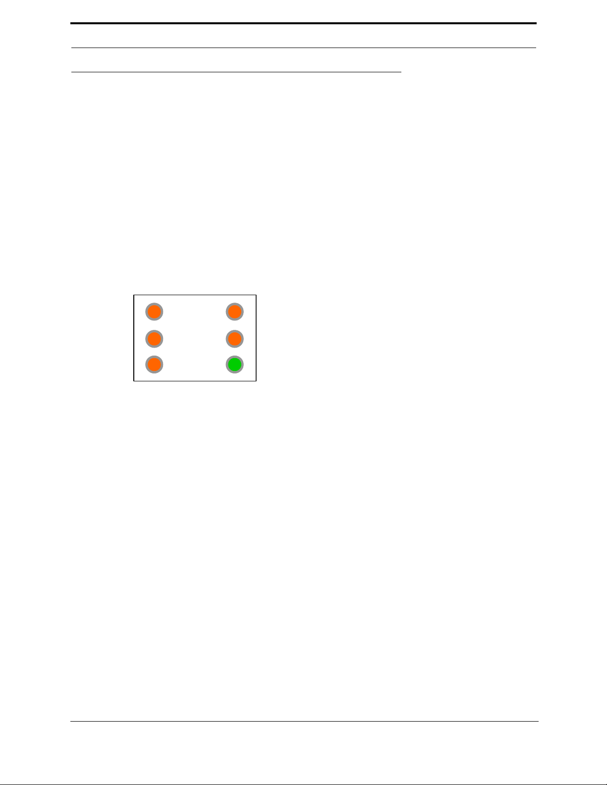
Troubleshooting with the Status Light Panel
The Status List Panel is located on the front of the Operator’s
Station, below the work surface area. It has six lights that are all
illuminated when the system is in proper working order. If one
or more lights are OFF, follow the process below to ascertain the
cause.
NOTE: Be sure to proceed down the table, starting with the
CONTROL POWER light.
CONTROL
OVERLOAD
STOP
STAR
24VDC
700-C 53
Troubleshooting
Light If ON: If OFF:
CONTROL
POWER
OVERLOAD
RELAY
E-STOP Go to STOP • Check to see the E-Stop button(s) is pulled out.
STOP Go to START • Check for 110 V AC between #2 and #6. If there is voltage, press
ST ART Go to 24VDC • Push the Start button. If the Start light remains unlit, push in the
Go to OVERLOAD
RELAY
Go to
E-STOP
• Check to see if the Control Transformer button is pulled out.
• Is the Disconnect switch on the main electrical cabinet set to
ON?
• Is there 208, 220, 440, or 575 VAC to the top side of the Control
Transformer (E3)? If not, check the fuses at the Fuse Block (E5),
and the contacts on the Control Transformer button on the switch
panel.
• Is there 110 VAC between #1 & #2 on the110 VAC Terminal
Strip? If not, check the fuse on the output side of the Control
Transformer. If fuse is good, check power coming out of Control
Transformer. If no power on the output side, and ther e is power
going into the top of the Control Transformer, replace the Control
Transformer. If there is power at the Control Transformer, check
the wiring of the black and white wire going from the Control
Transformer to the 110 VAC Terminal Strip.
• There is No over-load relay on this machine. If there is power to
the Status Light panel this light will be lit.
NOTE: Location and quantity of E-Stop buttons varies depending
on customer need. Typical locations for E-Stop buttons are near
the Rear Access Gate and near the Tool Changer Access Gate
• For Single E-Stop button machines
between #2 and #4. If no voltage, check to see if the E-Stop button is pulled out. If the E-Stop button is pulled out and E-Stop
light is OFF check the wiring. If no fault is found in the wiring turn
off the DL-NCB main power and check for continuity across the
pulled out E-S t op swi tch.
• For multiple E-Stop Button machines
on #2 check for 110 VAC on #4 through #5. If at any point no voltage is found trace the wires to find the associated E-Stop button
and check to see if that button is pulled out. If the E-Stop button
is pulled out and the E-Stop light is OFF check the wiring. If no
fault is found in the wiring turn off the DL-NCB main power and
check for continuity across the pulled out E-Stop switch.
• Check to see if the Back Gate is closed.
• Check to see if the Disconnect switch on the high-frequency
electrical cabinet is ON.
• Check for 110 VAC between #2 and #3A on the 110 VAC Terminal Strip. If there is 110VAC, go to next step: If the Disconnect
switch on the high-frequency electrical cabinet is OFF (closed)
and there is not 110 VAC between #2 and 3A, check the wiring.
• Check for 110 V AC between #2 and #3B. If there is 1 10 VAC, go
to next step: If the contact on the Rear Access Gate is closed and
there is no power between #2 and #3B, check for wiring problems.
the Start button. If no voltage, check the S top button to make sure
it is all the way out and not stuck in, then check the contact to
make sure it is closed. If still no voltage, check the wiring.
Start button and hold it in while a second person checks for voltage between #2 and #7. If there is 110 VAC, replace the ACR
relay. If there is no voltage while the button is held in, check the
wiring.
: Check for 110 VAC
: With on side of the meter
54 700-C

Troubleshooting Electrical Problems
24VDC Home the
700-C (see)
Check between DC+ and DC- for 24VDC. If no DC voltage, disconnect the
+ Brown/Red and - Blue/Black wires from the 24VDC power supply and
check for DC voltage where those wires were disconnected.
If no voltage:
• Check the input side for 110 VAC. If no 110 VAC, check the
fuse. If there is 110 VAC and no 24VDC, replace the 24VDC
Power Supply.
If there is 24VDC:
• Reconnect the + Brown/Red and - Blue/Black wires to the
24VDC power supply.
• Trace the + Brown/Red wire to the DC terminal block.
• Disconnect all brown wires from the + DC from the DC terminal
block except the + Brown/Red wire form the + 24VDC power supply.
• Check for +24VDC at between any –DC and +DC terminal on
the DC Terminal block.
• Reinstall the + brown wires one by one checking for +24VDC
after installing each + brown wire. If at any point no voltage is
found trace the last reinstalled wire and check for shorts.
Adjusting Limit Switches
If a machine suddenly stops in mid cycle, check the limit switches. A worn limit
switch arm or a misadjusted limit switch is more than likely the cause. (Another
potential cause is faulty photo eyes – for details.)
Depending on the model of limit switch on your machine, the pre-travel (amount
of movement from the limit switch arm’s resting position to the position at which
the switch actuates – with a “click”) is either 5 or 20 degrees. The DL-NCB has
700-C 55

Troubleshooting
five limit switches that have 5 degrees of pre-travel (3 on the X axis and 2 on the Y axis), and two
switches that have 20 degrees of pre-travel (on the Cutter head).
If the arm is moved to the full extent of its travel and you do not hear the limit switch “click”, the switch
needs to be adjusted. Use the set screw on the limit switch arm and adjust the arm to activate at the
desired degree of rotation (see illustrations
below).
Examples of Limit Switches:
56 700-C

Troubleshooting Photo Detectors
Troubleshooting Photo Detectors
Another cause of improper machine operation is a faulty or dirty photo detector.
There are two types of photo detectors, Through Beams and Photo Eyes.
• Through Beam Detectors consist of an emitter and detector. The emitter sends a light beam that is
sensed by the detector. The detector then sends 0VDC to the PLC. If the beam is broken the detector
sends 24VDC to the PLC.
• Photo Eye Detectors contain both emitter and receiver. If an object is within the Photo Eye’s sensing
field light from the emitter is reflected from the object back to the receiver. The Photo Eye then sends
24VDC to PLC. If no object is sensed the Photo Eye sends a 0VDC to the PLC.
If the photo detector is dirty, it will falsely sense the presence of a door, or other ob st ruction, and stop
the machine operation. If a suspected Photo Detector is clean check for the proper DC Voltage.
700-C 57

Troubleshooting
58 700-C

Touch Screen Troubleshooting
Moves to screen PLC
output screens. See
“PLC Output 00-17”
on page 65.
Moves to screen PLC
output input screens.
See “PLC Input 0017” on page 61.
Touch Screen Troubleshooting
Maintenance Screen
TABLE 8.
Title Notes
Reg/Split Shows status of Jamb type switch (SW00):
• Reg. = OFF
• Split = ON
See “Control Panel” on page 77. for switch location.
Reset Shows status of Reset switch (PB01 & (OPTIONAL) PB01A):
See “Control Panel” on page 77. for switch location.
Fire Shows status of Fire Guns switch (PB02 & (OPTIONAL) PB02A):
See “Control Panel” on page 77. for switch location.
Forward Shows status of Forward foot switch. (FS1)
See “Fixed and Movable Fence” on page 71. for location
Reverse Shows status of Seq. Reverse foot switch (FS2).
See “Fixed and Movable Fence” on page 71. for location
Enable movable Shows status of Enable Movable Guns switch (SW12 & (OPTIONAL) SW12B):.
See “Control Panel” on page 77. for switch location.
Enable fixed Shows status of Enable Fixed Guns switch (SW13 & (OPTIONAL) SW13A):
See “Control Panel” on page 77. for switch location.
Right header Shows status of Infeed head in place in place limit swi tch (L S14).
See “Moveably Fence - Inside view” on page 75.
700-C 59

TABLE 8.
TABLE 9. Staple sequence switch truth table
Program
Location
1
Program
Location
2
Program
Location
3
Staple
Sequence
OFF OFF OFF 0
ON OFF OFF 1
OFF ON OFF 2
ON ON OFF 3
OFF OFF ON 4
ON OFF ON 5
OFF ON ON 6
ON ON ON 7
Title Notes
Left header Shows status of Outfeed head in place limit switch (LS15).
See “Moveably Fence - Inside view” on page 75.
Guns in Shows status of Guns In limit switch (LS-17).
See “Fixed Fence - Inside view” on page 74.
Program Local 1
Program Local 2
Program Local 4
Program Local 8
. Shows status of Staple
Sequence switch
(SW30,SW31,SW32,SW33)
See “Main Control Panel” on
page 77. for location. The S ta-
ple Sequence switch converts
the decimal Staple Sequence
number to it’s binary equiv-
lant. See the truth table at
right.
Note: At present Program
Local 8 is not used.
Program Remote 1
Program Remote 2
Program Remote 4
Program Remote 8
Jamb Width A Shows status of the Jamb Width A switch (SW34 & (Optional) SW34A). See “Main Con-
Jamb Width B Shows status of the Jamb Width B switch (SW35 & (Optional) SW35A). See “Main Con-
Jamb Width C Shows status of the Jamb Width C switch (SW36 & (Optional) SW36A). See “Main Con-
Jamb Width D Shows status of the Jamb Width D switch (SW37 & (Optional) SW37A). See “Main Con-
60 700-C
Shows status of Staple Sequence switch (SW20,SW21,SW22,SW23) See “Remote Control
Panel (Optional)” on page 78. The Staple Sequence switch converts the decimal Staple
Sequence number to it’s binary equivalent. See “Staple sequence switch truth table” above
trol Panel” on page 77.
trol Panel” on page 77.
trol Panel” on page 77.
trol Panel” on page 77.

Touch Screen Troubleshooting
PLC Input 00-17
TABLE 10.
Title Notes
SS-00 Split-jamb Shows status of Jamb type switch (SW00):
• Reg. = OFF
• Split = ON
See “Control Panel” on page 77. for switch location.
PB-01 Reset Shows status of Reset switch (PB01 & (OPTIONAL) PB01A):
See “Control Panel” on page 77. for switch location.
PB-02 Fire guns Shows status of Fire Guns switch (PB02 & (OPTIONAL) PB02A):
See “Control Panel” on page 77. for switch location.
SS-03 RH/LH Not used.
FS-04 Seq. FWD Shows status of Forward foot switch. (FS1)
See “Fixed and Movable Fence” on page 71. for location
FS-05 Seq. REV Shows status of Seq. Reverse foot switch (FS2).
See “Fixed and Movable Fence” on page 71. for location
PE-06 Movable right Shows status of Movable right through beam (THRU06)
See “Heads” on page 73. for location.
PE-07 Movable left Shows status of Movable left through beam (THRU07)
See “Heads” on page 73. for location.
PE-10 Fixed right Shows status of Fixed right through beam (THRU010)
See “Heads” on page 73. for location.
PE-11 Fixed left Shows status of Fixed left through beam (THRU011)
See “Heads” on page 73. for location.
SS-12 Enable movable guns Shows status of Enable Movable Guns switch (SW12 & (OPTIONAL) SW12B):.
See “Control Panel” on page 77. for switch location.
700-C 61

TABLE 10.
Title Notes
SS-13 Enable fixed guns Shows status of Enable Fixed Guns switch (SW13 & (OPTIONAL) SW13A):
See “Control Panel” on page 77. for switch location.
LS-14 Infeed head in place Shows status of Infeed head in place in place limit switch (LS14).
See “Moveably Fence - Inside view” on page 75.
LS-15 Outfeed head in place Shows status of Outfeed head in place limit switch (LS15).
See “Moveably Fence - Inside view” on page 75.
PE-16 Door in machine Shows status of Door in Machine photo eye (PE16).
See “Fixed and Movable Fence” on page 71. for location.
LS-17 Guns in Shows status of Guns In limit switch (LS17).
See “Fixed Fence - Inside view” on page 74.
62 700-C

Touch Screen Troubleshooting
PLC Input 20-37
TABLE 1 1.
Title Notes
SS-20 Remote Sel-1
SS-21 Remote Sel-2
SS-22 Remote Sel-4
SS-23 Remote Not-8
SS-25 Metal Sill Not used
SS-26 Manual / Auto Shows status of 6’8”/8’0 switch
CR-27 Remote hand info Not used
Shows status of Staple Sequenc e switch (SW30, SW31,SW32,S W33) See “Remo te Control
Panel (Optional)” on page 78. for location. The Staple Sequence switch converts the deci-
mal Staple Sequence number to it’ s binary equivalent. See the tr uth table Figure 12, “Staple
sequence switch truth table,” on page 64
Note: At present Program Local 8 is not used.
See “Main Control Panel” on page 77. for location.
700-C 63

TABLE 1 1.
TABLE 12. Staple sequence switch truth table
Program
Location
1
Program
Location
2
Program
Location
3
Staple
Sequence
OFF OFF OFF 0
ON OFF OFF 1
OFF ON OFF 2
ON ON OFF 3
OFF OFF ON 4
ON OFF ON 5
OFF ON ON 6
ON ON ON 7
Title Notes
SS-30 Local Sel-1
SS-30 Local Sel-2
SS-30 Local Sel-4
SS-30 Local Not-8
. Shows status of Staple
Sequence switch
(SW30,SW31,SW32,SW33)
See “Main Control Panel” on
page 77. for location. The Sta-
ple Sequence switch converts
the decimal Staple Sequence
number to it’s binary equiva-
lent. See the truth table at
right.
Note: At present Program
Local 8 is not used.
SS-34 Jamb size A
SS-34 Jamb size B
SS-34 Jamb size C
SS-34 Jamb size D
Shows status of Staple Sequenc e switch (SW20, SW21,SW22,S W23) See “Remo te Control
Panel (Optional)” on page 78. The Staple Sequence switch converts the decimal Staple
Sequence number to it’s binary equivalent. See “Staple sequence switch truth table” above
64 700-C

Touch Screen Troubleshooting
PLC Output 00-17
TABLE 13.
Title Notes
SV-00 Move side clamp Shows status of control valve SV-00 (See “Control Valves” on page 76.)
which controls PC32 and PC35 (See “Heads” on page 73.)
SV-01 Infeed wheels up Shows status of control valve SV-01 (See “Control Valves” on page 76.)
which controls PC6 and PC26 (See “Infeed and Outfeed Wheels” on page 72.)
SV-02 Infeed wheels down Shows status of control valve SV-02 (See “Control Valves” on page 76.)
which controls PC6 and PC26 (See “Infeed and Outfeed Wheels” on page 72.)
SV-03 Fixed side clamp Shows status of control valve SV-03 (See “Control Valves” on page 76.) which controls
PC39 and PC36 ((See “Heads” on page 73.)
SV-04 Bot. Jamb clamp Shows status of control valve SV-04 (See “Control Valves” on page 76.) which controls
PC13, PC23 (See “Fixed Fence - Inside view” on page 74.) and PC14, PC24 (See “Move-
ably Fence - Inside view” on page 75.)
SV-05 Right end clamp Shows status of control valve SV-05 (See “Control Valves” on page 76.)
SV-06 Raise right guns Shows status of control valve SV-06 (See “Control Valves” on page 76.) which controls
PC33 and PC38 (See “Heads” on page 73.)
SV-07 Raise left guns Shows status of control valve SV-07 (See “Control Valves” on page76.) which controls
PC34 and PC37 (See “Heads” on page 73.)
SV-10 Outfeed wheels up Shows status of control valve SV-10 (See “Control Valves” on page76.) which controls
PC7 and PC7 (See “Infeed and Outfeed Wheels” on page 72.)
SV-11 Outfeed wheels down Shows status of control valve SV-11 (See “Control Valves” on page 76.) which controls
PC7 and PC7 (See “Infeed and Outfeed Wheels” on page 72.)
SV-12 Fire right movable Shows status of control valve SV-12 which control SG1 (See “Heads” on page 73.)
SV-13 Fire left movable Shows status of control valve SV-13 which control SG2 (See “Heads” on page 73.)
SV-14 Fire right fixed Shows status of control valve SV-14 which control SG3 (See “Heads” on page 73.)
SV-15 Fire left fixed Shows status of control valve SV-15 which control SG4 (See “Heads” on page 73.)
700-C 65

TABLE 13.
Title Notes
SV-16 Head clamp Shows status of control valve SV-16 (See “Control Valves” on page76.) which controls
PC3, PC4, PC5, PC9, PC10 bad PC11 (See “Moveably Fence - Inside view” on page 75.)
SV-17 Fixed guns in close Shows status of control valve SV-17 (See “Control Valves” on page 76.)
PLC Output 20-37
TABLE 14.
Title Notes
SV-20 Outfeed Assist cyl Shows status of control valve SV-20 (See “Control Valves” on page 76.) which controls
PC28 and PC8 (See “Infeed and Outfeed Wheels” on page 72.)
SV-21 3/4” Ret. Shows status of control valve SV-21 (See “Control Valves” on page 76.) which retracts
PC15, PC21 (See “Fixed Fence - Inside view” on page 74.) and PC16, PC22 (See “Moveably Fence - Inside view” on page 75.)
SV-22 3/4” Ext. Shows status of control valve SV-22 (See “Control Valves” on page 76.) which extends
PC15, PC21 (See “Fixed Fence - Inside view” on page 74.) and PC16, PC22 (See “Moveably Fence - Inside view” on page 75.)
SV-23 2” Ret. Shows status of control valve SV-23 (See “Control Valves” on page 76.) which retracts
PC15, PC21 (See “Fixed Fence - Inside view” on page 74.) and PC16, PC22 (See “Moveably Fence - Inside view” on page 75.)
SV-24 2” Ext. Shows status of control valve SV-24 (See “Control Valves” on page 76.) which extends
PC15, PC21 (See “Fixed Fence - Inside view” on page 74.) and PC16, PC22 (See “Move-
ably Fence - Inside view” on page 75.)
SV-25 Left end clamp Shows status of control valve SV-25 (See “Control Valves” on page 76.)
PL-26 No jamb error Shows status of 6’8”/8’0 switch. See “Main Control Panel” on page 77. for location.
Q-27 Not used
Q-30 Not used
Q-31 Not used
Q-32 Not used
Q-33 Not used
66 700-C

Touch Screen Troubleshooting
TABLE 14.
Title Notes
Q-34 Not used
Q-35 Not used
Q-36 Not used
CR-37 OK to feed door in Shows status of PLC output 37
700-C 67

68 700-C

Getting Help from Kval
Getting Help from Kval
Before you seek help, first try the troubleshooting procedures in.
If you are still not able to resolve the problem, contact our customer support engineers:
• In the U.S and Canada, call (800) 553-5825 or fax (707) 762-0485
• Outside the U.S. and Canada, call (707) 762-7367 or fax (707) 762-0485
• Email address is service@kvalinc.com
T echnical Support business hours are 4:00 AM to 4:30 PM Pacific Standard Time, Monday through Friday.
Product Return Procedure
If you’ve contacted Kval for help and it is determined that a return is necessary, use the procedure below
to return the machine or part.
Note: Non-Warranty returns are subject to a 15% restocking charge.
1. Obtain the packing slip and/or invoice numbers of the defective unit, and secure a purchase order
number to cover repair costs in the event the unit is determined to be out of warranty.
2. Reason for return: Before you return the unit, have someone from your organization with a technical
understanding of the 700-C system and its application include answers to the following quest ions:
• What is the extent of the failure/reason for return? What are the relevant error messages or error
codes?
• How long did it operate?
• Did any other items fail at the same time?
• What was happening when the unit failed (e.g., installing the unit, cycling power, starting other
equipment, etc.)?
• How was the product configured (in detail)?
• Which, if any, cables were modified and how?
• With what equipment is the unit interfaced?
• What was the application?
• What was the system environment (temperature, spacing, contaminants, etc.)?
3. Call Kval customer support for a Return Material Authorization (RMA). When you call:
• Have the packing slip or invoice numbers available.
• Have the documented reason for return available.
4. Send the merchandise back to Kval.
• Make sure the item(s) you are returning are securely packaged and well protected from shipping
damage
• Include the packing slip or invoice numbers.
• Include the documented reason for return.
• Include the RMA number with the parts package.
700-C 69

70 700-C

Part Locations
Fixed
Fence
In Feed
Out Feed
Key:
Reference Designator - I/O
I/O Description
FS4 - I004
Seq. Forward
FS5 - I005
Seq. Reverse
Movable
Fence
PE16 - I016
Door In Machine
Part Locations
Fixed and Movable Fence
700-C 71

Infeed and Outfeed Wheels
Fixed
Fence
In Feed
Out Feed
Key:
Reference Designator - I/O
I/O Description
Movable
Fence
PC26:
PC27:
PC28 - Q020
Assist Cylinder
Q001 - Retract
Infeed wheels up
Q002 - Extend
Infeed wheels down
Q010 - Retract
Q011 - Extend
Outfeed wheels down
Outfeed wheels up
PC6:
PC7:
PC8 - Q020
Assist Cylinder
Q001 - Retract
Infeed wheels up
Q002 - Extend
Infeed wheels down
Q010 - Retract
Q011 - Extend
Outfeed wheels down
Outfeed wheels up
72 700-C

Part Locations
In Feed
Out Feed
Movable
Fence
Fixed
Fence
Right Hand
Movable Head
Left Hand
Movable Head
Right Hand
Fixed Head
Left Hand
Fixed Head
Key:
Reference Designator - I/O
I/O Description
PC33 - Q006
Raise Right Guns
PC38
- Q006
Raise Right Guns
PC34 - Q007
Raise Left Guns
PC37 - Q007
Raise Left Guns
Through Beam
Junction Box
Through Beam
Junction Box
SG1 - Q012
Fire Right Movable
SG3 - Q014
Fire Right Fixed
SG2 - Q013
Fire Left Movable
SG4 - Q015
Fire Left Fixed
THRU06 - I006
Movable Right
THRU07 - I007
Movable Left
THRU10 - I010
Fixed Right
THRU11 - I011
Fixed Right
PC32 - Q000
Movable Side Clamp
PC35 - Q000
Movable Side Clamp
PC39 - Q003
Fixed Side Clamp
PC36 - Q003
Fixed Side Clamp
SV1 - Q012
Fire Right Movable
SV2 - Q013
Fire Left Movable
SV3 - Q015
Fire Left Fixed
SV4 - Q014
Fire Right Fixed
Heads
700-C 73

Fixed Fence - Inside view
Fixed
Fence
In Feed
Out Feed
Key:
Reference Designator - I/O
I/O Description
PC13 - Q004:
Bottom Jamb Clamp
LS-17 - I017
Guns In
PC25 - Q028
Head Clamps
(Inner)
LS14 - I014
Right Head
PC1 - Q026
Head Clamps
(Outer)
In Place
PC30 - Q034
Head Clamps
(Inner)
PC31 - Q036
Head Clamps
(Outer)
LS-15 - I0015
Outfeed head
In Place
PC15:
Q021: Retract 3/4” Cylinder
Q024: Extend 2” Cylinder
PC17:
Q023: Retract 2” Cylinder
Q022: Extend 3/4” Cylinder
PC21:
Q021: Retract 3/4” Cylinder
Q024: Extend 2” Cylinder
PC19:
Q023: Retract 2” Cylinder
Q022: Extend 3/4” Cylinder
PC23:
Q004: Bottom Jamb Clamp
PC25 - Q029
Head Clamps
(Inner)
PC29 - Q033
Head Clamps
(Inner)
74 700-C

Part Locations
Movable
Fence
In Feed
Out Feed
Key:
Reference Designator - I/O
I/O Description
PC14:
Q004: Bottom Jamb Clamp
PC5 - Q016
Head Clamps
(Inner)
PC3 - Q016
Head Clamps
(Outer)
PC9 - Q016
Head Clamps
(Inner)
PC11 - Q016
Head Clamps
(Outer)
PC16:
Q021: Retract 3/4” Cylinder
Q024: Extend 2” Cylinder
PC18
Q023: Retract 2” Cylinder
PC2 Manually operated
Width Lock
PC12
PC4 - Q016
Head Clamps
(Inner)
PC10 - Q016
Head Clamps
(Inner)
Manually operated
Width Lock
Q022: Extend 3/4” Cylinder
PC22:
Q021: Retract 3/4” Cylinder
Q024: Extend 2” Cylinder
PC20
Q023: Retract 2” Cylinder
Q022: Extend 3/4” Cylinder
PC24:
Q004: Bottom Jamb Clamp
Moveably Fence - Inside view
700-C 75

Key:
Reference Designator - I/O
I/O Description
SV-16 - Q016
Head Clamps
SV-17 - Q017
Fixed Guns In Close
SV-25 Left End Clamp
SV-20 - Q020
Assist Cylinder
SV-21 - Q021
Retract 3/4”
SV-22 - Q022
Extend 3/4”
SV-23 - Q023
Retract 2”
SV-24 - Q024
Extend 2”
Cylinder
Cylinder
Cylinder
Cylinder
SV-11 - Q011
Outfeed Wheels Down
SV-07 - Q007
Raise Left Guns
S-06 - Q006
Raise Right Guns
SV-05 - Q005
Right End Clamp
SV-04 - Q004
Bottom Jamb Clamp
SV-03 - Q003
Fixed Side Clamp
SV-00 - Q000
Movable Side Clamp
SV-02 - Q002
Infeed Wheels Down
SV-10 - Q010
Outfeed Wheels up
SV-01 - Q001
Infeed Wheels Up
Control Valves
76 700-C

Part Locations
Key:
Reference Designator - I/O
I/O Description
PB01 - I001
Local & Remote Reset
SW26 - I026 (Optional)
6’8/8’0
SW00 - I000
Jamb Reg/Split
PB02 - I002
Local & Remote Fire
PB34 - I034
Jamb Width A
SW13 - I013
Enable Fixed Guns
PB36 - I036
Jamb Width C
PB37 - I037
Jamb Width D
PB35 - I035
Jamb Width B
SW30,SW31,SW32,SW33:
I030: Program Select Local Select #1
I033: Program Select Local Select #8
I032: Program Select Local Select #4
I031: Program Select Local Select #2
SW1
Control Circuit Power
CONTROL CIRCUIT
OFF ON
STAPLE SEQUENCE
0
1
2
3
4
5
6
7
RESET 700-C
JAMB TYPE
REG. SPLIT
ENABLE FIXED
SIDE GUNS
OFF ON
ENABLE MOVABLE
SIDE GUNS
OFF ON
FIRE GUNS
JAMB WIDTH JAMB WIDTH
WIDTH ADJUST
PUSH
CLAMP
PULL
RELEASE
FIRE SIDE NAILER
Fire Side Nailer (Optional)
Nematic button
Width Adjust
Nematic button
Door Length
6’ 8”
8’ 0”
SW12 - I012
Enable Movable Guns
SELECT
LOCAL REMOTE
SW24 - I024
SELECT LOCAL/REMOTE (OPTIONAL)
Control Panel
Main Control Panel
700-C 77

Remote Control Panel (Optional)
Key:
Reference Designator - I/O
I/O Description
SW12A - I012
Enable Movable Guns
SW4A - I002
Local & Remote Fire
SW34A - I034
Jamb Width A
SW13A - I013
Enable Fixed Guns
SW36A - I036
Jamb Width C
SW37A - I037
Jamb Width D
SW35A - I035
Jamb Width B
SW20,SW21,SW22,SW23:
I030: Program Select Remote Select #1
I033: Program Select Remote Select #8
I032: Program Select Remote Select #4
I031: Program Select Remote Select #2
STAPLE SEQUENCE
0
1
2
3
4
5
6
7
RESET 700-C
ENABLE FIXED
GUSIDE GUNS
OFF ON
ENABLE MOVABLE
SIDE GUNS
OFF ON
FIRE GUNS
JAMB WIDTH JAMB WIDTH
WIDTH ADJUST
PUSH
CLAMP
PULL
RELEASE
FIRE SIDE NAILER
Fire Side Nailer (Optional)
Nematic button
Width Adjust
Nematic button
SW1A - I001
Local & Remote Reset
78 700-C

Part Locations
Infeed
Outfeed
Head Jamb Stapling (Optional)
700-C 79

80 700-C


http://www.kvalinc.com
Contacting KVAL
Phone and Fax:
In the U.S and Canada, call (800) 553-5825 or fax
(707) 762-0485
Outside the U.S. and Canada, call (707) 762-7367
or fax (707) 762-0485
Email: service@kvalinc.com
http://www.kvalinc.com
Customer Service
Mailing address:
Customer Support Department
Kval Incorporated
825 Petaluma Boulevard South
Petaluma, CA 94952
 Loading...