

Kuzma Stogi Reference Owners manual

INSTRUCTION MANUAL
FOR
KUZMA TONEARMS
S T O G I A N D
S T O G I R E F E R E N C E
KAT d. o. o. Kuzma Audio Trade Hotemaže 17 a
4205 PREDDVOR
SLOVENIA tel. 386 4 2535450 fax 386 4 2535454

CONTENTS
I. GENERAL DESCRIPTION 3
II. PACKING LIST 4
III. UNPACKING 4
IV. MOUNTING AND ADJUSTING 5
A. Mounting Tonearm 5
B. Mounting Cartridge 8
C. Tracking Force Adjustment 9
D. Height (VTA) Adjustment 10
E. Tangentional Cartridge geometry adjustment 11
F. Fine VTA Adjustment 15
G. Azimuth Adjustment 16
H. Bias Adjustment 18
I.Fine azimuth Adjustment 19
J. Cueing Device Adjustment 19
V. GENERAL MAINTENANCE 20
VI. MINOR PROBLEMS 21
A. Pin Connector Breaks Off from Internal Wiring 21
B. Broken Bias Thread 22
C. Hum and Buzz 23
VII. TRANSPORT AND PACKING 24
A. With tonearm on Turntable 24
B. Packing (Fig. 29) 24
_________________________________________________________________
STOGI/STOGI REFERENCE 2 KUZMA
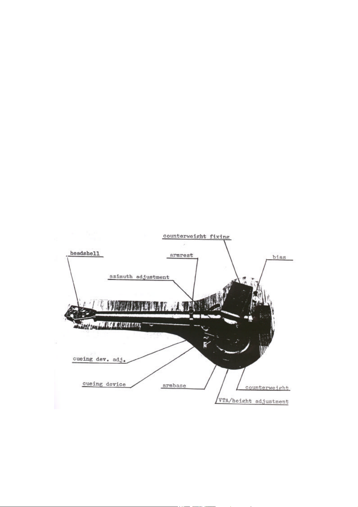
I. GENERAL DESCRIPTION
The main structure and headshell are both machined from solid aluminimum blocks
while the tube is of specially treated aluminium which is internally damped. The tube
also allows rotation for azimuth adjustment. Stogi reference tonearm has conical tube
with different adjustment.
The quality bearings are carefully selected and individually checked and tested before
assembly. They can each support 20 Kg. and are mounted free of play with minimal
friction in all planes.
Stogi incorporates a number of extra features including adjustable cueing device,
removable finger litf, precisely calibrated counterweight and simply adjustable bias.
The arm is wired throughout with cardas wires or Van del Hul cables and comes
equipped with its own full accessories kit. It will accept all cartridges and can be fitted
most quality turntables.
_________________________________________________________________
STOGI/STOGI REFERENCE 3 KUZMA

II. PACKING LIST
1. Tonearm with fingerlift.
2.Counterweight.
3. Base.
4. In small bag:
a) Three socket head screws M5 x 35 mm and three washers for fixing base.
b) Allen keys: 5 mm for attaching base to armboard, 3 mm for height adjustment
(VTA), 2,5 mm for fixing counterweight, bias and cueing device adjustment.
c) Bag containing two headsocket screws M 2.5 x 12 mm and nuts for fixing
cartridge plus Allen key 0.7 mm for removing fingerlift.
5. Two protractors, one for mounting tonearm on turntable and the other for cartridge
geometry adjustment.
6. Instruction Manual.
III. UNPACKING
1. Remove polystyrene cointainer from box.
2. Remove tape from sides and lift top half of polystyrene container (marked TOP).
3. Remove small polystyrene insert.
4. Holding the pillar not tube , lift tonearm in one hand and remove from plastic bag
with other, holding by pillar. Observe bias and thread while so doing.
5. At this stage tonearm can be rested upside down on C shape.
6. Remove all other parts. (See packing List).
_________________________________________________________________
STOGI/STOGI REFERENCE 4 KUZMA
IV. MOUNTING AND ADJUSTING
A. Mounting Tonearm
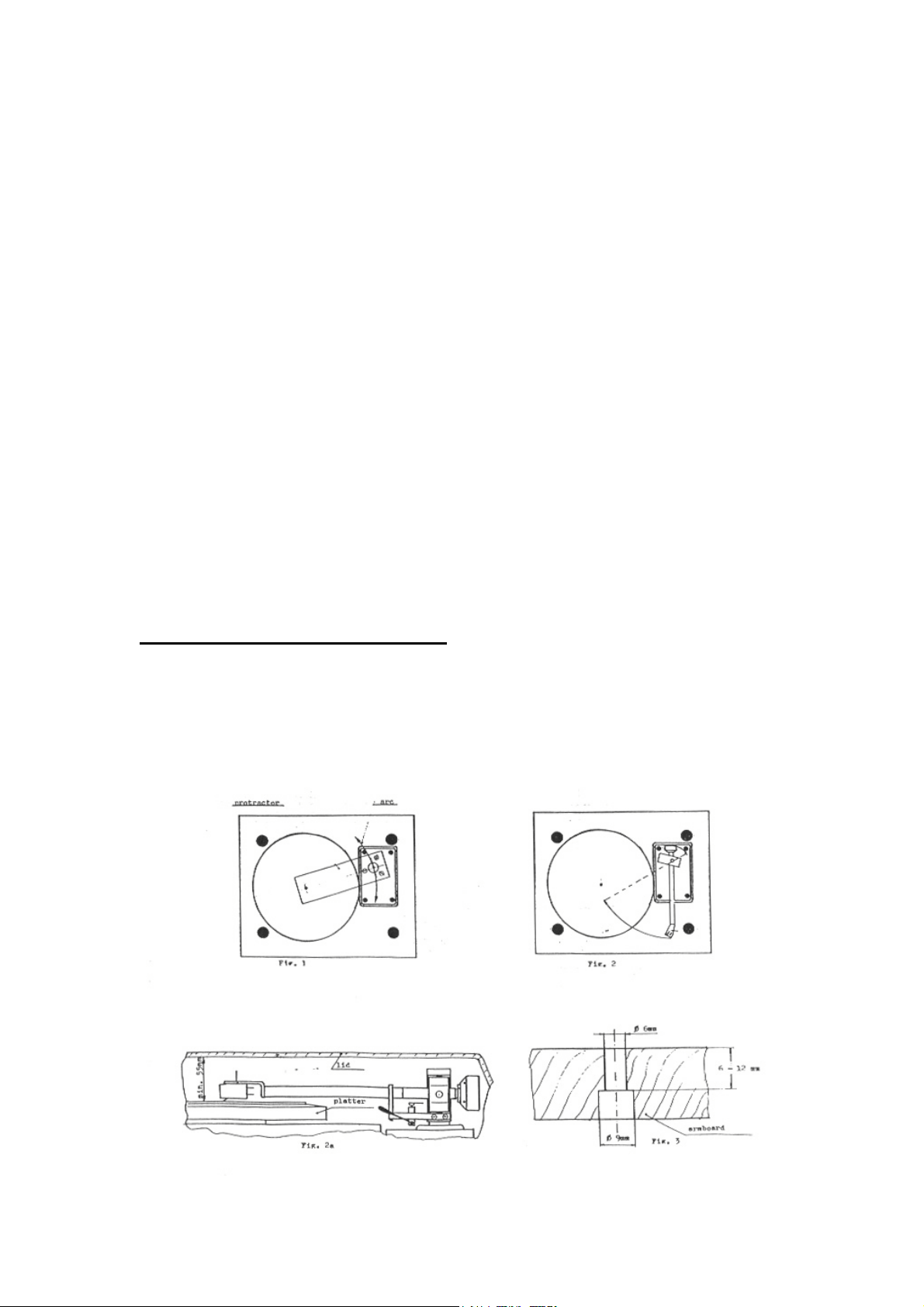
1. Take tonearm mounting protractor and place on spindle of turntable. The cut-out is
similar to standard Linn cut-out. (Fig. 1)
2. Mark position of holes as indicated on protractor on tonearm mounting board.
Ensure that there is adequate space in front for tube and headshell and behind for
counterweight, in order to avoid problems of lid closure. Check also that screw
positions will be over cut-out on subchassis, unless screws are to be sunk. It is wise
before cutting to hold tonearm in position over marks and judge if position of
tonearm on board will be correct, bearing in mind these criteria. (Fig. 2) Otherwise
precise position of tonearm is unimportant providing it lies on protractor arc.The
height of tonearm with cartridge mounted is 55 mm above record. (Fig. 2 a).
3. Remove tonearm board from turntable.
4. Check that thickness of board is between 6 mm and 12 mm, if so make cuts as
marked.
NOTE: If board is thicker than 12 mm
Either a) obtain screws of length that will go through armboard and into base to a
depth of approximately 5 mm, remembering washer or
b) sink the screw heads by first drilling a large hole of about 9 mm with drill and then
drilling hole of smaller dimension through this. (Fig. 3)
_________________________________________________________________
STOGI/STOGI REFERENCE 5 KUZMA
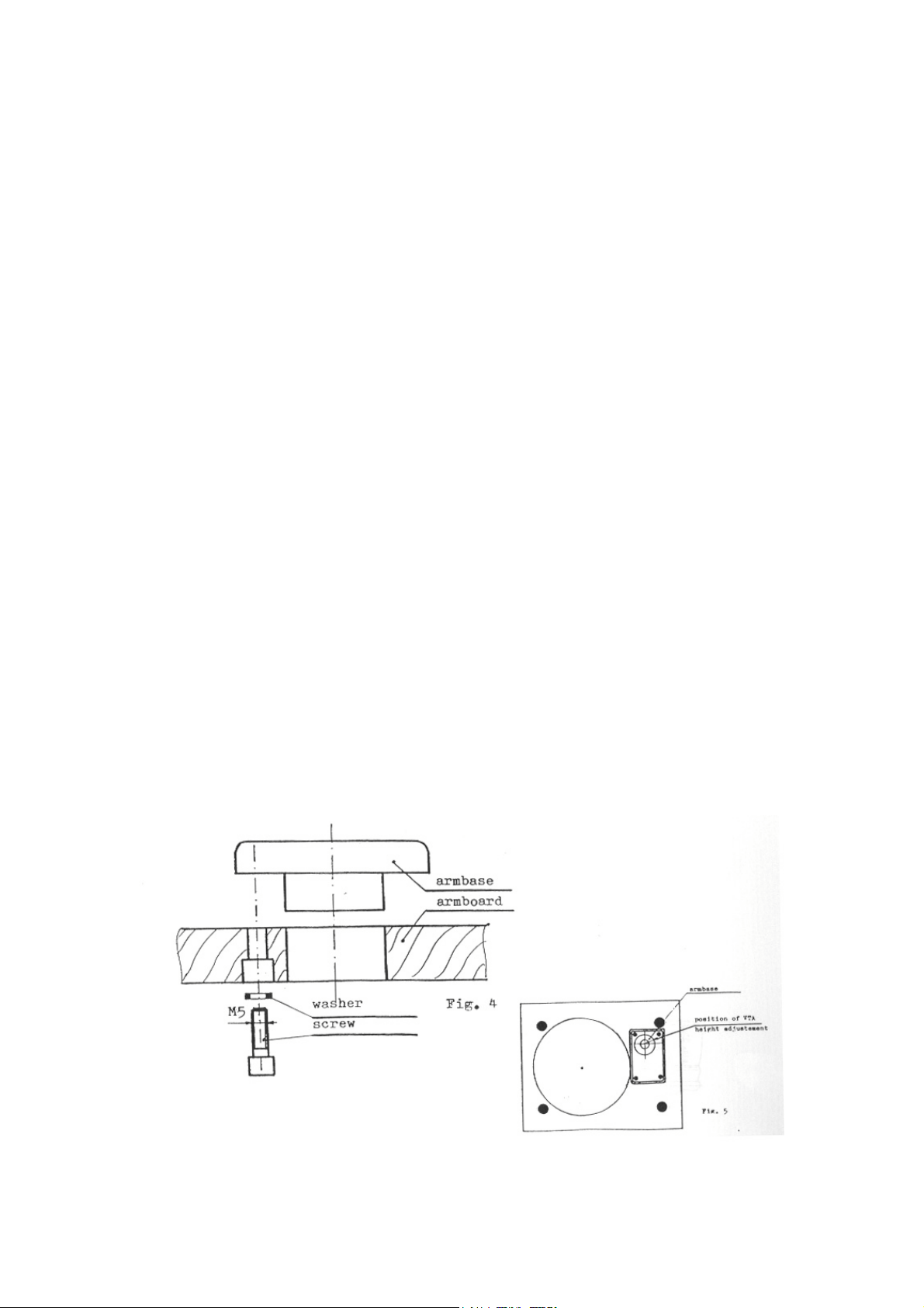
5. To fix base to armboard you will need the three socket head screws, spring washers
and Alley key 5 mm. Fit washers on screws and insert into underside of tonearm
board and up into tonearm base. (Fig. 4). Position base so that height adjustment
(VTA adjustment) screw is at top right position, i. e. 2 o’clock and tighten screws
using Allen key. Remember that screws are of harder material than tonearm (steel
and aluminium) so do not overtighten as this could damage base. (Fig. 5)
6. Replace tonearm board on turntable.
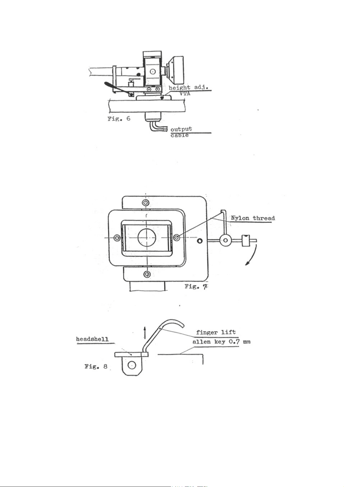
7. Insert tonearm cable through hole in base, then the pillar and fix at suitable height
using Allen key 3 mm at height adjustment screw in base. (Fig. 6)
8. Screw on counterweight so that thread is covered. This may take a little time.
9. It may now be necessary to adjust the suspension on the turntable due to the added
weight of the tonearm.
10. Fix tonearm cable onto turntable ensuring that there is adequate cable to allow for
height adjustment. If turntable has a suspended subchassis, position cable in such a
way that subchassis has freedom of movement.
11. The phono plugs are marked in the standard way: left - white, right - red, and
should be inserted into phono inputs. The connector at the end of the grounding
wire should be connected to GND on preamplifier.
12. Check that bias and thread are correctly positioned (it may have tangled during
handling). (Fig. 7)
13. For optimum performance you may wish to forego the convenience of the finger
lift. If so, this should now be removed using Allen key 0.7 mm, loosening screw
and easing out lift. Replace screw in hole. (Fig. 8)
_________________________________________________________________
STOGI/STOGI REFERENCE 6 KUZMA
_________________________________________________________________
STOGI/STOGI REFERENCE 7 KUZMA
B. Mounting Cartridge
You will need Allen key 2.5 mm plus the two screws and nuts M 2.5.
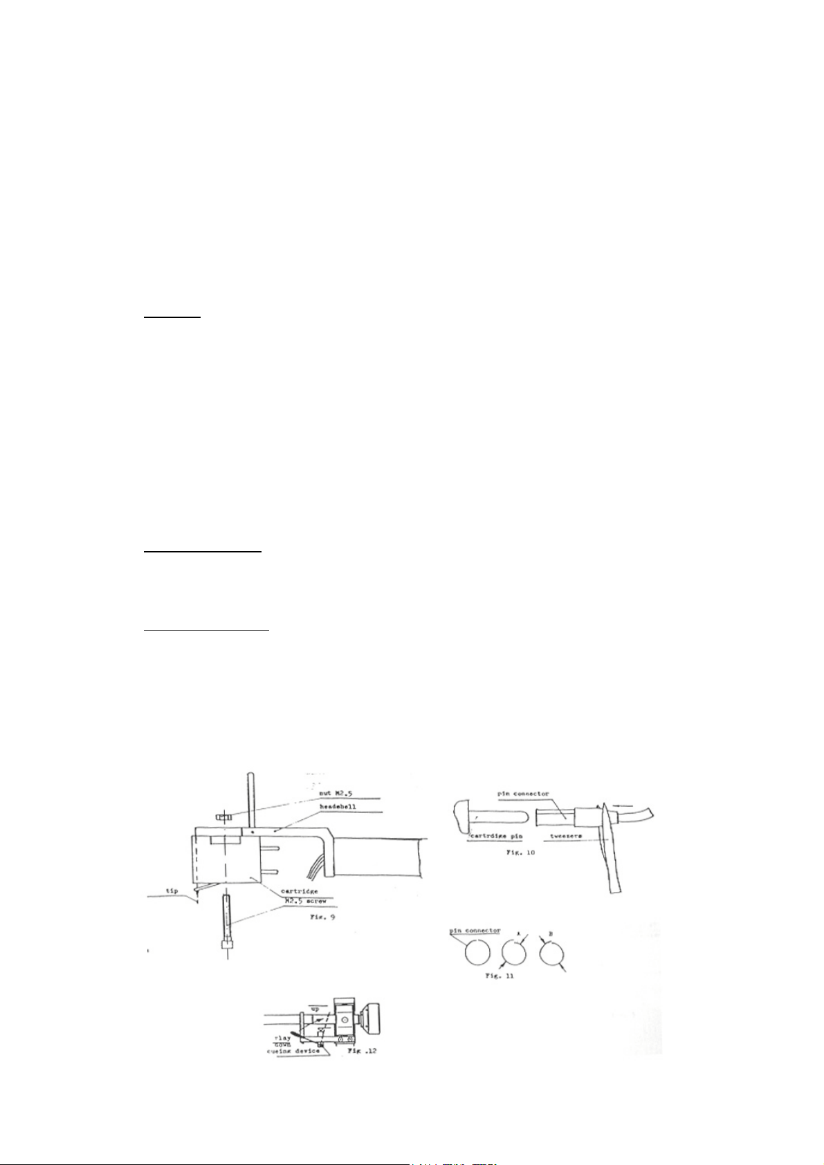
1. Keeping stylus guard on cartridge, insert screws from undeneath cartridge through
slots in headshell and screw on the two nuts manually. (Fig. 9) The tip of the
cantilever should be level with the end of the headshell (viewed from side).
2. Fix by slightly tightening screws using Allen key. Ensure that nuts have fitted into
ledge around slots.
NOTE: It may be found easier to remove tube from armrest to give a little
more room.
3. Using tweezers, push the pin connectors into cartridge according to code
Red - right
Green - right ground
White - left
Blue - left ground
The connectors will slip snugly onto pins of the majority of cartridges, (Fig. 10)
however:
If pins are too fat with tweezers firmly push connector onto pin. Connector will
open slightly. Do be careful, however, that tweezers do not slip and damage
cantilever.
If pins are too slim then connectors should be squeezed with tweezers to make hole
slightly smaller. First squeeze as in A then as at B then slip connectors onto pins.
(Fig. 11)
4. Put cueing device into ‘play’ position, ie. down, release tube from armrest and
adjust counterweight until tube is balanced ie. floats in a horizontal position slowly
back towards the armrest. Prior to final balancing remove stylus guard. (Fig. 12)
_________________________________________________________________
STOGI/STOGI REFERENCE 8 KUZMA
 Loading...