

Kuzma STOGI-REF313110513 User Manual
Instruction manual
KUZMA STOGI REF 313 TONEARM
2011-5
1
Serial Number: ….
KUZMA LTD
INSTRUCTION MANUAL FOR STOGI REF 313 tonearm
The Stogi Ref 313 tonearm is very precisely engineered pieces of audio equipment. However
the construction is robust and requires minimal maintenance for optimal performance.
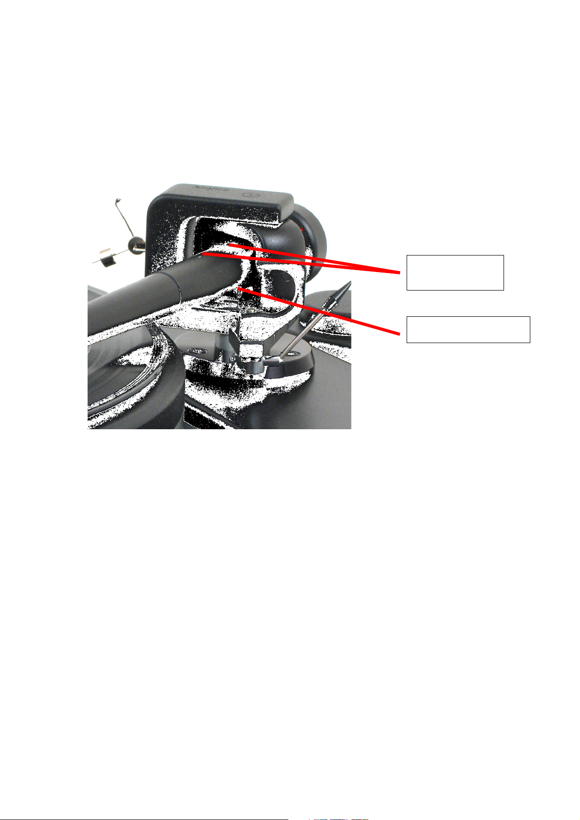
Azimuth fixing
Azimuth adjustment
Fig 1.
CONTENTS: Page
1.0. General description 3
2.0. Unpacking 4
3.0. Tonearm Setup 4-7
4.0. Tonearm adjustment 8-12
4.1. Adjustment of tracking force 8
4.2. Adjustment of tangential geometry 8-9
4.3. Adjustment of VTA 9
4.4. Adjustment of azimuth 10-11
4.5. Bias adjustment 11
4.6. Adjustment of cueing device 11-12
5.0. Maintenance 12
6.0. Transport 13
7.0. Troubleshooting 13-14
2

1.0. General description:
The Stogi Ref 313 tonearm has the same basic construction as the Stogi Ref arm. The main
difference is that Stogi Ref 313 has q 12 inch ( 313mm) long tonearm tube.
The Stogi Ref 313 has a very sophisticated, precise and repeatable azimuth adjustment
mechanism with zero play and a very rigid locking mechanism.
The main structure, conical tube and headshell are machined from solid aluminum blocks. Our
own unique detachable headshell is incorporated.
The quality ball bearings are carefully selected and individually checked and tested before
assembly. They can each support 20 Kg and are mounted free of play with minimal friction in
all planes.
Stogi Ref 313 arms incorporate features such as an adjustable height cueing device, precisely
calibrated counterweight and simply adjustable bias.
The arm is wired throughout with high quality Cardas wires and comes equipped with its own
full accessories kit. It will accept all cartridges and can be fitted on most quality turntables.
Technical data:
Mass: 980 gr
Effective length : 313 mm
Mounting distance: 300 mm
Offset angle: 17.4 degrees
Effective mass: 13 g
VTA adjustment: yes
Azimuth adjustment: yes worm drive
Bias adjustment: yes
Cables: single
Arm mount: Kuzma & Stogi
3

2.0.0. Unpacking:
2.1.0. Packing list:
Tonearm with fingerlift; counterweight; armbase; instruction manual; protractor for cartridge
geometry adjustment and a bag containing:
Bag:
Sets of 3 socket head screws M6x16 mm, M6x20 mm, M6x25 (for Stabi Ref), M6x 30 mm,
three washers, three spring washers (wooden armboards) for fixing base.
Allen keys: 5 mm for attaching armbase to armboard, 3 mm for height adjustment
(VTA), 2mm for cartridge and azimuth, 1,5 mm for fixing counterweight, bias and cueing
device adjustment.
Small bag containing 2 headsocket screws M2.5 x 5mm, M2.5x8 mm, M2.5x 12mm and nuts
for fixing cartridge plus Allen key 0.7 mm for removing fingerlift.
Open the box carefully and remove the top cover. Ensure that the armboard on the turntable has
the correct cut-out (main central hole must be 30- 40mm in diameter).
Remove the armbase and prepare it for fixing onto the turntable.
Holding the pillar not the tube, lift the tonearm out. Observe bias and thread while so doing.
The tonearm can be rested upside down on the C shape.
Remove all other parts.
3.0.0. Tonearm Setup:
3.1.0. Armbase Setup:
3.1.1. Armboard cutout:
Take the tonearm mounting protractor and place on spindle of turntable. The Stogi cut-out is
similar to the standard Linn cut-out but with a 300mm pivot to spindle distance.(You can also
use a Kuzma cutout)
Mark the position of holes on the tonearm mounting board as indicated on protractor.
Ensure that there is adequate space in front for tube and headshell and behind for
counterweight, in order to avoid problems of lid closure. Check also that screw
positions will be over the cut-out on subchassis, unless screws are to be sunk. It is wise
before cutting to hold tonearm in position over marks and judge the position of the
tonearm on the board will be correct, bearing in mind these criteria. Otherwise the
precise position of the tonearm is unimportant providing it lies on the protractor arc.
The height of the tonearm with cartridge mounted is 55mm above record.
Remove tonearm board from turntable and check that the thickness of board is between 6 mm
and 22 mm, if so make cuts as marked.
4

3.1.2. Armbase mounting:
To fix armbase to armboard you will need the correct length of three socket head screws,
washers and Alley key 5 mm. Fit washers on screws and insert into underside of tonearm board
and up into tonearm base. Position base so that height adjustment (VTA adjustment) screw is at
top right position, i. e. 2 o’clock and tighten screws using Allen key.
Remember that the screws are of harder material than the armbase (aluminum) so do not over
tighten as this could damage the base.
Note: if armboard is thicker then 22 mm:
Either obtain screws of a length that will go through the armboard and into the base to a depth
of approximately 5mm, or sink the screw heads by first drilling a large hole of about 9 mm with
a drill and then drilling a hole of smaller dimension through this.
Put tonearm board back on turntable.
3.2. Tonearm mounting:
Note: Be sure that the tonearm is not too low.
Insert tonearm cable through hole in armbase, then the pillar and fix it at a suitable height using
Allen key 3 mm at the height adjustment screw in the base.
Screw on counterweight so that the thread is covered.
It may now be necessary to adjust the suspension on the turntable due to the added
weight of the tonearm.
Fix tonearm cable onto the turntable ensuring that there is adequate cable to allow for
height adjustment. If the turntable has a suspended subchassis, position cable in such a way that
the subchassis has freedom of movement.
The phono plugs are marked in the standard way: left - white, right - red, and
should be inserted into phono inputs. The connector at the end of the grounding
wire should be connected to GND on preamplifier.
Check that the bias and thread are correctly positioned (it may have tangled during
handling).
For optimum performance you may wish to forego the convenience of the finger lift. If so, this
should now be removed using Allen key 0.7mm, loosening screw
and easing out lift. Replace screw in hole.
Remove wire securing arm tube.
5
 Loading...