

Kuzma 4Point Instruction Manual

1
KUZMA 4POINT TONEARM
Instruction manual Serial Number: …..
2008-6
2
KUZMA LTD
INSTRUCTION MANUAL FOR 4POINT tonearm
The 4POINT tonearm is a very precisely engineered piece of equipment, however, the
construction is robust and requires minimal maintenance for optimal performance.
Fig.1
CONTENTS: Page
General description 3
Basic Setup 5-6
Setting up the tonearm 6-8
Adjustment of tracking force 9
Adjustment of tangential geometry 9
Adjustment of VTA 9
Adjustment of azimuth 10
Adjustment of bias 10
Damping 10-11
Adjustment of cueing device 12
Maintenance 13
Transport 13
Problems 13
Appendix 1 (tangential geometry) 14-16
Appendix 2 (fine azimuth) 17
Appendix 3 (fine bias) 18
Protractors 19
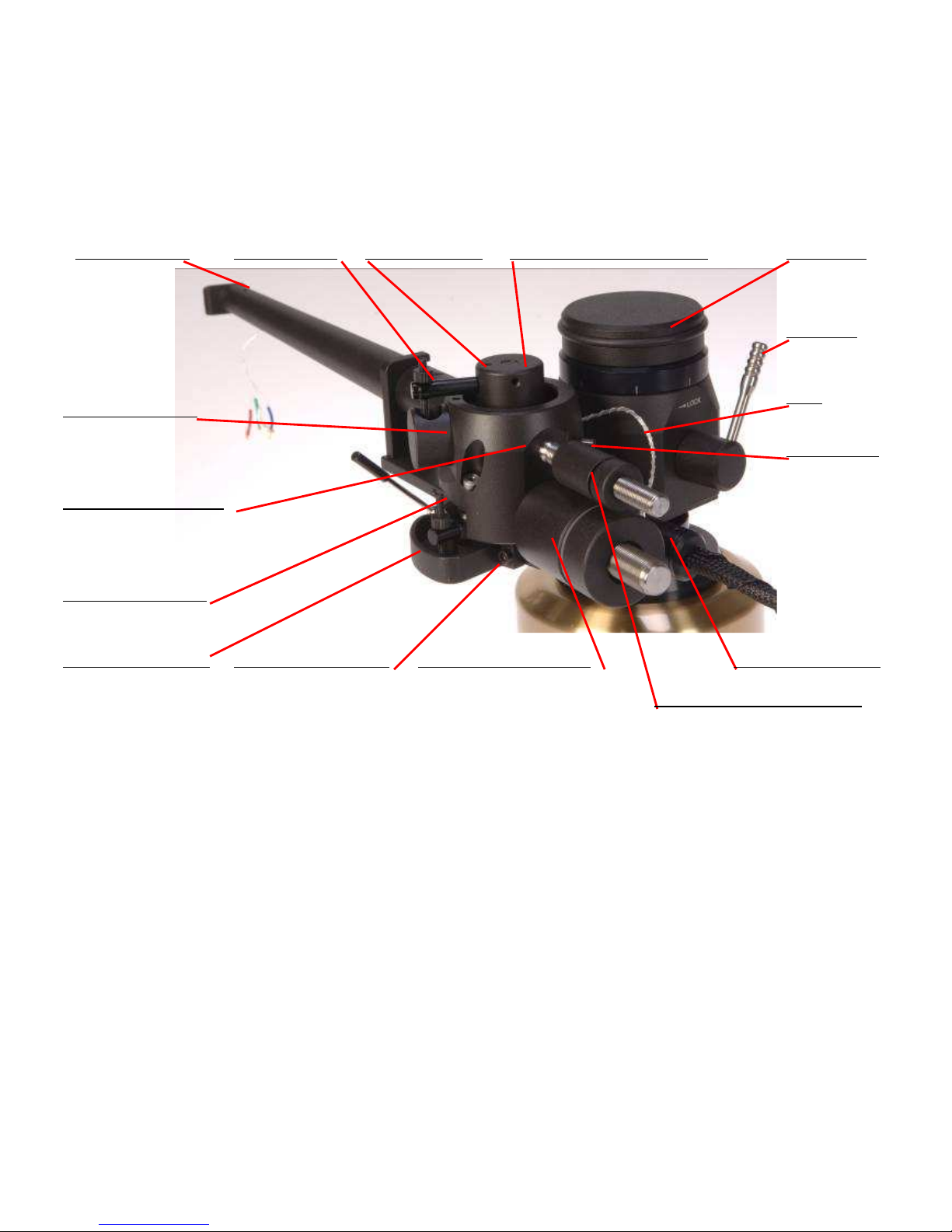
headshell lock vertical paddle vert. paddle lock horizontal bearing assembly VTA tower
VTA lock
loop
pin for cable
cable - play position
counterweight tracking force
main counterweights horizontal trough lock trough–horizontal
horizontal paddle
main tube assembly
trough - vertical

3
General description :
This differs from other arms by incorporating several unique features. The zero play bearing
is configured on 4 points. There is very precise VTA adjustment and, despite a longer
effective length of 280 mm (11 inches), fits the standard mounting distance of 212mm ( for 9
inches arms).
The heart of the new construction is a unique 4 point bearing. The first set of two points
(similar to a double unipivot bearing) allows vertical movement. The second set of two points
allows horizontal movement. All four points have minimal friction and zero play in all
playing directions thus ensuring the cartridge platform and the cartridge itself move with very
low friction and minimal vibration across the record. It is normal to feel slack in the bearings
in certain directions.
The whole construction is mounted on a rigid VTA tower which allows very precise VTA
adjustment while playing, without any loss of rigidity, yet with up to 0.01 mm of precision
and zero play.
The main tube is constructed and machined from solid aluminium, similar to our tangential
Air line arm. The main counterweight balances the tonearm and there is a second small
counterweight with which the tracking force can be finely adjusted. Azimuth can be adjusted
in small repeatable increments with zero play, by means of an Allen key.
A feature of the tonearm is a unique detachable headshell. The electrical connection is via
standard pins but the headshell can be simply removed by unscrewing with an Allen key. The
headshell is fixed with a precise hexagonal locking system giving the same rigidity as with a
fixed headshell.
Two separate troughs damp vertical and horizontal resonances and can be finely adjusted
independently. The troughs can be removed from the tonearm.
Internal wiring is of superior special alloy silver wires. One set of 4 wires runs unbroken
from the cartridge pins to the termination box and further along into a 1.4 m long tonearm
cable with silver Eichmann bullet connectors. The second set of 4 wires runs from the same
cartridge pins to the termination box to female Cardas RCA connectors thus allowing use of
any RCA plugged tonearm cable from termination box, to phono preamp input. This gives so
called biwiring on this tonearm and a lot of flexibility with choice of no compromise cables.
Note:
If both sets of cables are connected, bear in mind that an MC cartridge will see it as »double
loading«. If you want to set up 2000 Ohms, with both sets of wire connected to the same
phono unit, then 4000 Ohms loading should be set.

4
Fig. 2
Technical data:
Mass: 1650 gr
Effective length : 280 mm ( 11 inch)
Mounting distance: 212 mm
Offset angle: 19.50 degrees
Distance from spindle to
horizontal bearing: 264 mm
Effective mass: 13 g
VTA adjustment: yes
Azimuth adjustment: yes
Bias adjustment: yes
Vertical damping: yes
Horizontal damping: yes
Cables: biwiring
Arm mount: Air line 212 mm
azimuth lock VTA scale - fine horizontal bearing assembly
vertical bearing point azimuth adjustment
bias

5
1. Unpacking
Open the box carefully and remove top covers.
The tube with vertical bearing points is packed separately (tube assembly) on the top of the
box. Please do handle with care and when put aside, ensure that nothing is touching the
bearing points. Bear in mind how you will handle the termination box and output cable.
The horizontal bearing assembly is permanently mounted on the main VTA arm tower. This
is blocked during transport. (Fig. 2)
First remove the armbase and prepare it for fixing onto the turntable. Be sure that the
armboard on the turntable has the correct cut-out (main central hole must be 40 mm in
diameter).
2. Basic set up
Armbase:
Mount the armbase on the turntable. If the pre-cut has a thread, then use three screws and fix
them from the top through the armbase into the armboard thread. A second way is to use a
ring underneath and fix three screws into this ring, which will then hold the armbase very
tightly. Be sure that you position the armbase so as to give access to an Allen key for fixing
arm into armbase (towards the back of the turntable). Also check, when mounting the arm on
other turntables, that you allow enough clearance for counterweights and correct position of
the tube in relationship to the platter. Due to the bearing construction, there is only a limited
arc which the arm tube can travel in a horizontal way. Rotation of the VTA arm tower of the
arm, to achieve the correct distance of 264 mm, is done with a protractor after the basic setup.
VTA arm tower:
Insert the VTA arm tower into the armbase. Ensure that the height is such, that the top
surface of the platform holding cueing device is at the same height as the record. Fix it with
an Allen key. The vertical bearing cups should be at the same height as the record. Also
check that the VTA adjustment is in the middle position, to allow fine VTA adjustment up
and down 5 mm each way.
With 1.5 mm Allen key, release the small ring which is on the fixing pillar below the VTA
arm tower. Now it will drop down and touch the armbase. Fix the ring again and release the
VTA arm tower. You now have the correct height but you can freely rotate the VTA arm
tower horizontally. Rotate it to such a position that the distance from the centre of the record
to the centre of the horizontal bearing is 264 mm. (Use protractor by gently pulling apart
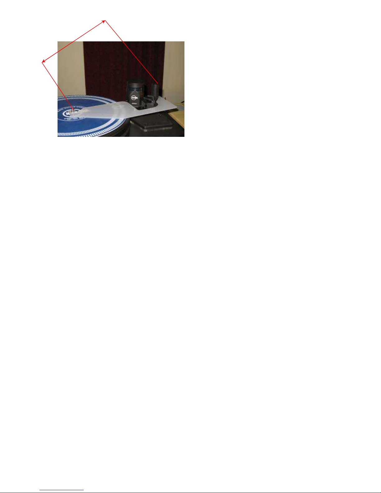
trying to achieve max distance) Now fix VTA arm tower. (Fig.3)
6
Fig.3 Protractor for pivot to spindle distance
Remove the fixing foam on the horizontal bearing assembly. Check that the bias thread is
fixed and gently rotate horizontal bearing assembly from one to another extreme. It is only
possible to make approximately ¼ of a turn. It is normal to feel slack in the bearings.
Tube assembly:
Carefully take the tube assembly with cable (there is also a heavy connection box) and gently
position it around the horizontal bearing assembly so that the two points will fit into the
appropriate bearing cups. Position it into the armrest.
(Fig. 2&4)
Remove cable from the tube assembly by releasing the black cable holder from the transport
position with the 1.5 mm Allen key. Fix it to the empty pin at the back of the VTA tower,
below the VTA locking lever. Fix it in such way, that the naked wires will go upwards
towards the tube in a loop. Be sure, that the VTA arm tower is fixed in the armbase, because
the weight of the cable might otherwise rotate it. (Fig.1)
3. Setting up the tonearm
Connecting tonearm:
Check the horizontal movement of the tube to ensure that the headshell will reach the inner
grooves (approximately to the edge of record label), but will not travel to the centre of the
record. Also check the arm wire loop and connect the tonearm cable into the phono sockets
of the preamp. (Fig.1)
You can add a second set of RCA cables into the termination box and connect this to a second
phono unit input. We do not recommend that both cables are connected to the same two input
of a single phono preamp. Disconnect one set. Secure the termination box using a Velcro
strip or long screws onto the turntable stand, somewhere to the rear.
Due to the high tonearm mass, turntable levelling and suspension should be checked and
adjusted according to the turntable manual.
264 mm
 Loading...