

Kutzner + Weber ZUK 130, ZUK 150, ZUK 150S, ZUK 180 Installation Instructions Manual
Hearth – Kitchen – Domestic
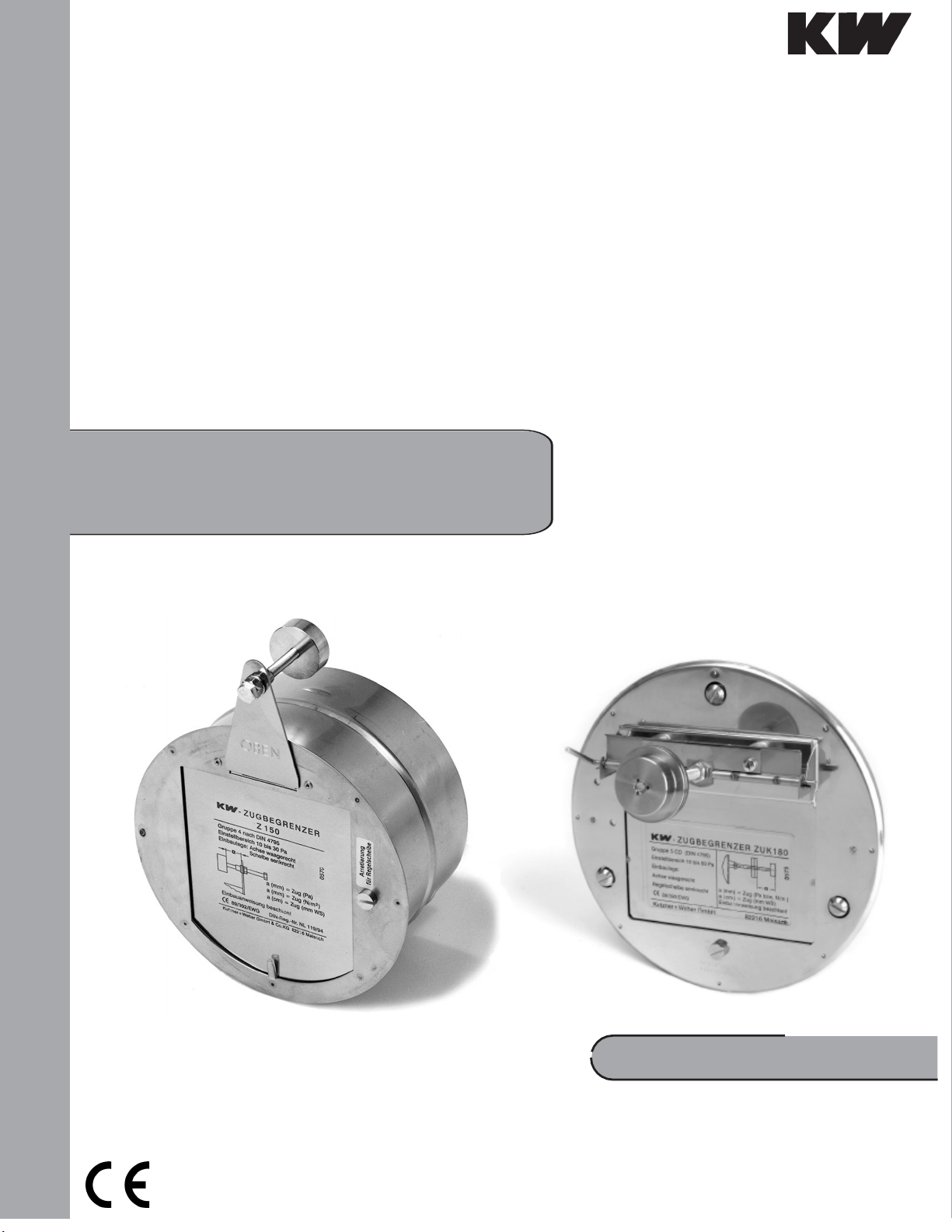
Barometric Dampers
For non-positive pressure appliances
Barometric Dampers
ZUK 130 /
ZUK 150 / ZUK 150S / ZUK 180
KUTZNER + WEBER
Kutzner + Weber is certified according to DIN EN ISO 9001:2008
INSTALLATION INSTRUCTIONS
Safety
Barometric dampers should only be connected to nonpositive pressure appliances. Non-positive pressure
appliances include gas, oil, and solid fuel appliances.
Barometric Dampers shall be installed in the same room as
the appliance it is serving.
Warning:
Install barometric dampers in accordance with
local and national codes which may include ANSI
Z223.1 (NFPA 54), NFPA 31, NFPA 211
If a flue gas silencer is used, the barometric damper
should be
installed downstream as there may be positive pressure in
the connector pipe upstream of the silencer.
Installation
Insert the barometric damper into the connector tee with the
control wheel in the vertical axis. Now adjust the barometric
damper carefully with an air level (fig. 2, axis of control wheel
horizontal, frame and control wheel vertical). Now fasten the
barometric damper by tightening the clamping screw (fig. 1).
Refer to manufacturer’s instruction for the required draft for
the appliance
. If the barometric damper is placed within 3 feet of
the appliance outlet, the typical draft setting would be between
-0.02”-0.08” wc.
Not following these instructions may prevent the barometric
damper from operating properly. This may disrupt the
combustion process of the appliance.
Start-Up (functional test)
After installing and setting the ba rometric draught regulator
verify the blade moves easily on the bearings. To do this, pull
the control wheel down manually and let it go to verify that
the blade swings back into position.
regulator,
is correct and
operate the appliance to verify that
flue gas does not spill into the occupied space.
After setting the draught
the draft setting
If the draught regulator is installed properly and set per
appliance manufacturers requirements, it will run
flawlessly increasing efficiency and reducing standby
losses in firing systems.
Setting the Nominal Value (required draft)
The default setting for the KW Barometric Draft Regulator is the
highest setting. The required draft for the fireplace is set by
turning the control wheel (fig. 3). The measure "a" in inches
corresponds to the draft in inches WC. After setting the control
wheel, it should be locked in position. Turn the locking nut
clockwise to unlock the control wheel (fig. 1).
Maintenance
The KW Barometric Dampers require virtually no maintenance.
Check on a regular basis to ensure dust does not accumulate
on the bearing. If necessary (before the heating period begins),
the bearings can be lubricated with a
Do not lubricate or grease the bearings excessively since
this only increases the build-up of sediments.
drop of non-resinous oil
If dirt or soot has set on the control wheel, it needs to be
Technical Data
Model
max. flue gas temperature (DIN 1860)
Setting range (required draft in neg. pressure)
ZUK 130 ZUK 150 ZUK 150-S ZUK 180
750 °F 750 °F 750 °F 750 °F
0.04–0.10” 0.04–0.14” 0.04–0.14” 0.04
Air flow rate at ∆p 0.02” wc 45 CFM 80 CFM 80 CFM
Air flow rate at ∆p 0.08” wc 75 CFM 130 CFM 130 CFM
carefully to maintain the accuracy of the barometric damper.
–0.24”
110 CFM
160 CFM
Air flow rate at ∆p 0.16” wc 95 CFM 175 CFM 175 CFM 210 CFM
Response pressure of pressure relief valve
max. open cross-section pr. relief valve
Air flow rate as combined sec.-air
appliance at ∆p 0.08” wc > 60 CFM
The air flow rates given for ∆p refer to the negative static pressure above the set point of the barometric damper.
> 0.40” wc > 0.40” wc ------ > 0.40” wc
10 in
2
5.25 in
------
2
------ 5.25 in
> 130 CFM > 120 CFM
removed
2
 Loading...