

Page 1
GCU-20
Automatic Engine Control Unit
WARNING
Disconnect all electric power to the machine before
installation.
Protection Functions
Engine fail to start
Engine tries 3 times to start
Engine Low Oil Pressure Protection
Shutdown activated after 3 seconds
Oil Pressure Switch Type NO or NC
Auxiliary Shutdown
Shutdown activated after 3 seconds delay by NO contact
Engine High Water temperature Protection
Shutdown activated after 3 seconds delay by NO contact
Engine Over-speed Protection
Shutdown activated after 3 seconds
50 Hz activated at 55 Hz – 60 Hz activated at 66 Hz
Engine Under-Speed Protection
Shutdown activated after 5 seconds
50 Hz activated at 45 Hz – 60 Hz activated at 54 Hz
No Speed Signal Present Protection
Shutdown activated after 5 seconds (MPU use only)
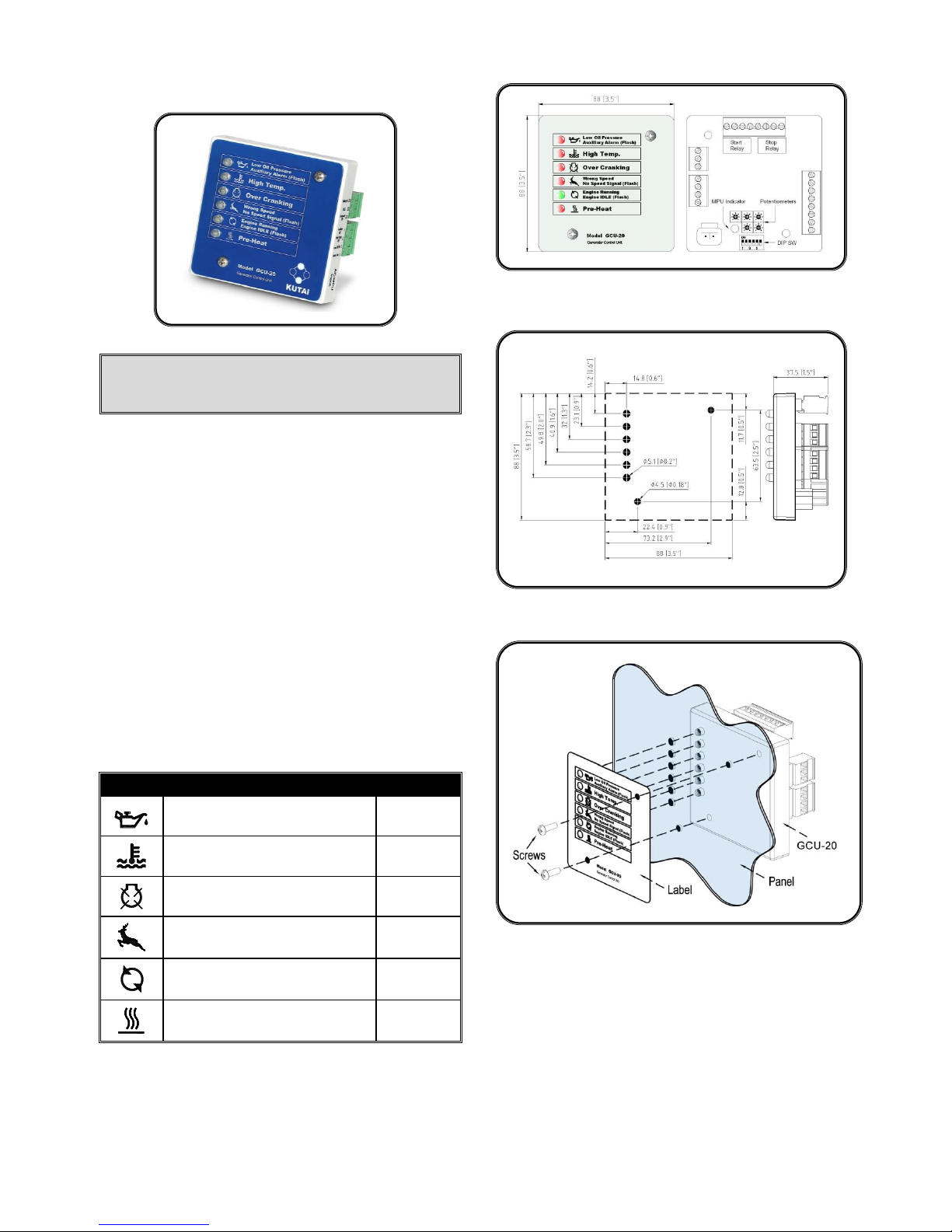
Icon Reference Table
ICON
DESCRIPTION
ACTION
Low Oil Pressure Alarm
Auxiliary Alarm (Flashing)
Shutdown
High Water Temperature Alarm
Shutdown
Over Crank Alarm
Shutdown
Wrong speed Alarm
No Speed Signal Alarm (Flashing)
Shutdown
Engine Running Indicator
Engine IDLE Indicator (Flashing)
Engine Pre-Heat Indicator
Pre-Heat
Physical Dimensions
Mounting Pattern
Installing Panel
Page 2
Auxiliary Alarm (Flash)
Pre-Heat
Wrong Speed
Engine IDLE (Flash)
Engine Running
No Speed Signal (Flash)
Over Cranking
High Temp.
Low Oil Pressure
Model GCU-20
A
B
D
C
E
MPU Indicator
Speed Sensor
Connector
MPU indicator
in Green
60
Potentiometers & DIP Switches Detail
Adjustments
On the back of the GCU-20 we have five adjustment pots that
modify time delay functions.
●
A Engine Pre-Heat
Adjustable from 2 to 30 sec
●
B Energized to STOP
Adjustable from 1 to 15 sec
●
C Engine Cool-down
Adjustable from 0 to 300 sec
●
D Starter Cranking time
Adjustable from 1 to 15 sec
●
E Engine Idle (Governor)
Adjustable from 0 to 300 sec
Function Setting
Also In the back, the GCU-20 we have six dip / switches that
set specific working parameters.
SW 1 Oil Pressure Switch Used for Crank Disconnect
ON - Disable OFF - Enable
SW 2 Oil Pressure Switch Type
ON - Normal Open OFF - Normally Close
SW 3 Engine Stop Setting
ON - Energize to Start OFF - Energize to STOP
SW 4 Generator Frequency (Ignore if it is a Water Pump)
ON – 50 Hz OFF – 60 Hz
SW 5 MPU Setting
ON - Enable (used to Program Speed)
OFF - Disable
SW 6 Speed Signal Type
ON - Use MPU for speed sensing
OFF - Use AC generator frequency for speed sensing
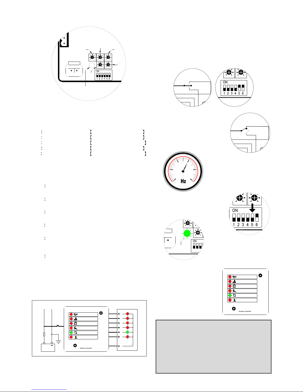
Lamp Test Function
Applying battery (+) signal to terminal 1 (Lamp Test Terminal)
the GCU-20 turns on all the front panel LEDs and
annunciator lamps.
+
Battery
10A
Model GCU-20
No Speed Signal (Flash)
Engine Running
Engine IDLE (Flash)
Pre-Heat
Wrong Speed
J1 J2 J4J3
Lamp Test
Low Oil Pressure
High Temp.
Over Cranking
Auxiliary Alarm (Flash)
Remote Annunciator
J7J6J5
Using with MPU
If you use the MPU for speed sensing instead of the
generator frequency you must set (Switch 6 to ON), and
depending on flywheel size (different generators has a
different MPU frequencies). This nominal frequency MUST
be set FIRST.
It is easy, if you follow the procedure below.
Step 1:Move Switches 5 & 6 to “ON” before starting engine.
Step 2:Start engine, by moving
panel switch to “TEST”
(Manual Start)
Step 3 : Run the engine
normally at its rated
speed. (60 or 50 Hz)
or pump rated RPM
Step 4:Now quickly move
Switch 5 to “OFF”
Step 5:When MPU LED turns
GREEN setup is
complete.
MPU Setup failure
If setup fails, the control module
shuts down the engine and
immediately flashes ON all the
LEDs on the front panel.
Check MPU and wiring before
repeating this setup again.
WARNING
If the MPU signal is used for speed sensing (Switch 6
ON), but MPU frequency set up has not yet been
completed the MPU indicator will flash RED and the
engine will not run under any condition.
However, if the user tries to start the engine a “No
Speed Signal” warning LED will continue to flash
indicating that the user should repeat the set up of the
MPU frequency setting or switch to generator
frequency sensing.
Select Switch
Start
Remote
OFF
Auto
Test
Batt(-)
Select Switch
Remote
Batt(-)
Start
OFF
Test
Auto
Page 3

Specification
ITEM
SPECIFICATION
DC Supply
9 36 Vdc
Alternator Input Range
5 300 Vac
Alternator Input Frequency
50/60 Hz
MPU Signal Input Range
+/-2V to +/-70 Vac Peak
Rated MPU Frequency
100 10,000 Hz
Operating Temperature
-20 to 70 ˚C
Relative Humidity
Under 90 %
Power Consumption
Under 3W
Weight
206 g +/- 2%
Terminals Detail
PIN No.
CURRENT
MAX.
DESCRIPTION
1
10mA
Auxiliary switch input
2
10mA
Temperature switch input
3
10mA
Oil switch input
4
10mA
Lamp test input
5
10A
Start signal output
6
10A
Battery negative input
7
10mA
AUTO switch input
8 – 9
10mA
Remote start signal input
10
10mA
Test switch input
11
10A
Fuel / Stop signal output
12
300mA
Pre-heat signal output
13 – 18
300mA
Annunciator signal output
19
300mA
Warm-up signal output
20
1A
Annunciator common used only
Don’t use as main ground connection
21
1A
Accessory ON signal output
22
1A
IDLE control output
23
10A
Battery positive input
TEST Operation
To initiate a start sequence moves the external toggle switch
to the on TEST (Manual Start) position.
First, the pre-heat timer begins by energizing terminal 12. If
Pre-Heat is not uses, simple no not use this terminal.
Second, the Engine Fuel Solenoid energizes terminal 11,
and idle terminals 22.
Third, after a 1 sec. delay, the starter motor energizes, and
the engine cranks for the duration of the crank timer.
Fourth, after the engine (start / fires), the starter motor
disengaged and locked out by using the 18-Hertz signal from
the generator or the signal from the MPU. Alternatively, the
oil pressure switch can serve as an additional back up crank
disconnect.
Fifth, after the engine fires and if the Engine Idle option is
used, the ENGINE RUNNING LED will continuous flashing in
idle indicating the status is IDLE. (If engine idle is not used set adjustment, “E” full counterclockwise).
Sixth, if the engine does not start the first time the module
will try again to start the engine 2 more times and stop after
the third try.
If the generator fail to start, move the select
switch to the OFF (Reset) position, Find out
why the engine failed to start before making
any more start attempts.
Seven, after the generator starts, the module allows Oil
Pressure, Engine Temperature and engine speed to stabilize
without triggering any faults for 20 seconds.
Moving the toggle switch to the OFF position, Stops the
engine immediately.
Automatic (Remote Start) Operation
In the “AUTO” mode, the GCU-20 control module monitors
input terminals 8 & 9 for a “REMOTE START” signal. Should
a “REMOTE START” signal be detected a start sequence
similar to previous manual start cycle is initiated.
Removing the Remote Start signal automatic activates the
Cool Down Timer and after the Cool Down ends, the Fuel
Solenoid is (de-energized or energized as the case may be)
bringing the generator or engine to a complete stop.
Should the Remote start signal be re-activated during the
cooling down period, the set will immediately return to normal
operation.
NOTE
Even if the generator is executing Engine Cool down
Timer, The Module protection system remain in operation
and if any failure occurs, the module bypasses the Engine
Cooling Timer shutting down the generator immediately.
OFF Operation
The OFF position places the module into its Stop or Reset
mode.
In RESET mode the operator must clear any fault conditions.
Selecting OFF when the engine is running automatically
STOPS the generator. The fuel supply will be removed and
engine will be brought to a standstill. Should a remote start
signal be present while operating in this mode, a remote start
will not occur.
Page 4

Wiring Diagram Using Generator AC Frequency Sensing
Wiring Diagram Using MPU Frequency Sensing
Please link to http://www.kutai.com.tw for detailed manual
17
L1
L2
L3
N
20
18
19
23
Relay
Start
2
3
4
21
1
22
15
16
14
13
Relay
Stop
65 987
L2
L3
LOAD
N
L1
RW
G
Pre-Heat Relay
RS
RF
Start Relay
Batt(-)
Select Switch
Fuel / Stop Relay
Auto
Test
OFF
Remote
Start
RP
Common(-)
Warm-up Relay
Alarm Lamp
Engine Run Lamp
Wrong Speed Lamp
Over Crank Lamp
High Temp. Lamp
Low Oil Lamp
J3
RW
J1 J2
Remote Annunciator RA-20
J4 J5 J6 J7
Battery
+
10A
RA
RI
Batt(+)
Lamp Test SW
Low Oil SW
High Temp. SW
Auxiliary SW
Acc. ON Relay
Idle Relay
Model GCU-20
Wrong Speed Lamp
High Temp. Lamp
Over Crank Lamp
Engine Run Lamp
Common(-)
Alarm Lamp
Warm-up Relay
1
Auxiliary SW
High Temp. SW
Lamp Test SW
Low Oil SW
2
4
3
Acc. ON Relay
Batt(+)
23
21
22
Start
Relay
Stop
Relay
Low Oil Lamp
Model GCU-20
Batt(-)
Remote
J5 J7J6J2 J4J3J1
19
20
17
18
16
15
13
14
Idle Relay
Start
Battery
+
10A
Start Relay
Fuel / Stop Relay
Pre-Heat Relay
Test
Auto
OFF
Select Switch
Magnetic Pick-Up
5 6 7 8 9
RA
RI
RS
RF
RP
RW
L3
L1
L2
N
L3
L2
L1
N
RW
Remote Annunciator RA-20
LOAD
G
 Loading...