

Page 1
KUTAI ELECTRONICS INDUSTRY CO., LTD.
TEL : +886-7-8121771 FAX : +886-7-8121775 Website : www.kutai.com.tw
Headquarters : No.3, Ln. 201, Qianfu St., Qianzhen Dist., Kaohsiung City 80664, Taiwan
Analog / Digital,Single-phase detection,Excitation Current 3.5 Amps.
For use in brushless, self-excited (shunt) generators
Compatible with Leroy Somer* R250/R230, AVR
* All manufacturer names and numbers are used for reference purpose only
and do not imply that any part is the product of these manufacturer.
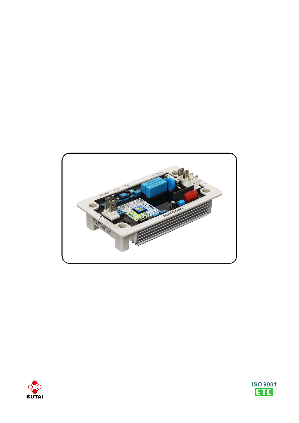
ADVR-250
Generator Automatic Voltage Regulator
Operation Manual
Page 2
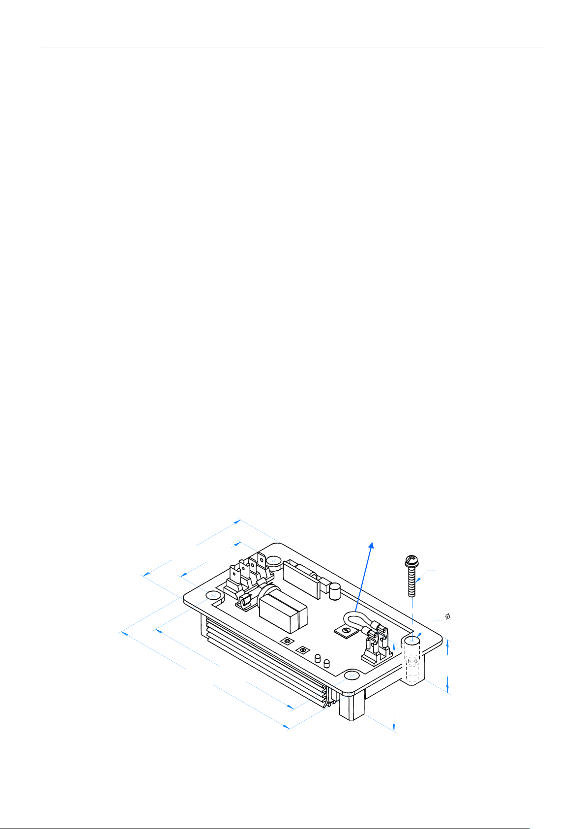
Figure 1 Outline Drawing
Sensing Input ( 0V, 110V ) Average Reading
Under Frequency Protection (Factory Presets)
Voltage 85 140 Vac, 1 phase 2 wire
50 Hz system knee point at 48 Hz
Frequency 50/60 Hz, Potentiometer setting
60 Hz system knee point at 58 Hz
Excitation Output ( E+, E- )
Over Excitation Current Limiting
120V 1 phase Continuous 63 Vdc 3.5A
Excitation Current 5 A +/- 10 %
Max. 110 Vdc 5A for 10 secs.
Resistance Min. 18 ohms, Max.100 ohms
Voltage Thermal Drift
Fuse Spec. Slow blow 5 x 20mm 8A
Less than 3% at temperature range -40 to +70 ˚C
External Voltage Adjustment (1K ohm )
Under Frequency Knee Point Thermal Drift
Max.+/- 14% @ 1 K ohm 1 watt potentiometer
Less than +/- 0.1 Hz at -40 to +70 ˚C
Voltage Regulation
Environment
Less than +/- 0.5% (with 4% engine governing)
Operating Temperature -40 to +70 ˚C
Storage Temperature -40 to +85 ˚C
Build Up Voltage
Relative Humidity Max. 95%
5 Vac 25 Hz residual volts at power input terminal
Vibration 5.5 Gs @ 60 Hz
Soft start ramp time
Dimensions
3 seconds +/- 10%
140.0 (L) x 81.0 (W) x 46.0 (H) mm
5.51 (L) x 3.19 (W) x 1.81 (H) inch
Typical System Response
Less than 20 milliseconds
Weight
300 g +/- 2%
EMI Suppression
0.66 lb +/- 2%
Internal electromagnetic interference filtering
Static Power Dissipation
Max. 4 watts
Unit : mm
[inch]
[3.19"]
81.0
[5.51"]
140.0
[4.53"]
115.0
[1.06"]
27.0
[1.96"]
50.0
[1.81"]
46.0
M4 L25
8.5
[0.33"]
Connection Terminals:6.35 mm (1/4 inch)
Flag Terminals ( “Fast-On” terminals ).
SECTION 1 : SPECIFICATION
SECTION 2 : APPEARANCE / DIMENSIONS / INSTALLATION DRAWING
___________________________________________________________________________________________
2 ADVR-250
Page 3

0V, 110V:
Power Supply
and Sensing Input
* Over Excitation Current Limiting (O/C)
When the excitation current is greater than or exceeds 5A the AVR will reduce the excitation output to limit the
excitation current. At this time the generator output voltage will be in a very unable state (the greater the load the
lower the voltage). Over current protection will not interrupt the excitation field output.
* LAM (Load Acceptance Module) Outline
When the generator experiences momentary increases in load (more 40% of generator capacity) voltage and
engine speed will decrease. The process of recovering voltage and engine speed will produce a situation where
output voltage and engine speed fluctuates. In order to reduce the level of volatility, after a load is added the
engine speed will slow, lowering the total power output of the generator and delaying recovery.
The low frequency knee point setting should be below a nominal setting for 2 Hz to cause the output voltage and
engine speed to have a smooth recovery.
The LAM function allows choice of reduction settings of 13% and 25%. If the generator has a fluid drive (hydro) it
is recommended not to use the LAM function.
E+, E-:
Excitation Output
VOLT:Voltage Adjustment
STAB:Stability Adjustment
O/C LED:Over Excitation
Current Limiting Status
Indicator.
When over excitation current
limiting function is operating
(Excitation Current > 5A),this
LED will light up.
U/F LED:Under Frequency
Protection Status Indicator.
1K ohm:
External VR
input, Must be
shorted with a
jumper when
not in use.
U/F function and LAM potentiometer:
See SECTION 4 for more detail
110V
0V
E+
E-
1 KΩ
STABVOLT
U/FO/C
0
1
2
3
4
5
6
7
8
9
ADVR-250
Figure 2
SECTION 3 : POTENTIOMETER ADJUSTMENT
___________________________________________________________________________________________
ADVR-250 3
Page 4

4
3
2
1
SPECIAL
65Hz
57Hz
KNEE
KNEE
KNEE
5
6
7
8
9
0
0
1
2
3
4
5
6
7
8
9
60Hz
50Hz
ATTENTION
The potentiometer settings must correspond to
the rated frequency. An error in settings could
cause damage to the generator.
SECTION 4 : U/F PROTECTION & LAM
FUNCTION SELECTION
The Under Frequency Protection (U/F) and LAM
function can be selected using the potentiometer.
Figure 3
___________________________________________________________________________________________
4 ADVR-250
50 Hz Systems
0: Under Frequency knee point 48 Hz, LAM function
“OFF”. Use when transient loads are below 40% of
rated generator capacity.
1: Under Frequency knee point 48 Hz, LAM function
set to (13%), Use when transient loads are
between 40 – 70% of rated generator capacity.
2: Under Frequency knee point 48 Hz, LAM function
set to (25%). Use when transient loads are greater
than 70% of rated generator capacity.
60 Hz Systems
3: Under Frequency knee point 58 Hz, LAM function
“OFF”. Use when transient loads are below 40% of
rated generator capacity.
4: Under Frequency knee point 58 Hz, LAM function
set to (13%), Use when transient loads are
between 40 – 70% of rated generator capacity.
5: Under Frequency knee point 58 Hz, LAM function
set to (25%). Use when transient loads are greater
than 70% of rated generator capacity.
Special Systems
6: Under frequency knee point 57 Hz, LAM function
“OFF”. Under a load, engine speed variations can
be greater than 2 Hz.
7: Under frequency knee point 65 Hz, LAM function
“OFF”.
8: Factory setting of the Under Frequency knee point
is 48 Hz and LAM function “OFF”. This option is
supplied for special projects, which must be
ordered separately and are set at the factory.
9: Under frequency knee point 47.5 Hz,LAM function
“OFF”. Under a load, engine speed variations can
be greater than 2 Hz.
Page 5

110V
0V
E+
E-
1 KΩ
STAB
VOLT
U/FO/C
0
1
2
3
4
5
6
7
8
9
ADVR-250
1000 Ohm
EXT. VR
~
G
Field
R SN T
110V
0V
E+
E-
1 KΩ
STABVOLT
U/FO/C
0
1
2
3
4
5
6
7
8
9
ADVR-250
1000 Ohm
EXT. VR
~
G
Field
R SN T
ATTENTION
1. Before using a Megger or a Withstand Voltage Tester, removes the wires connecting to the AVR to
prevent high voltage damage to the regulator.
2. Improper setting of under-frequency protection could cause the output voltage of the unit to drop or
become unstable under with changes in load. Avoid making any changes to the U/F setting unless
necessary.
190/220 Vac
110 Vac
SECTION 5 : CONNECTION DIAGRAMS
Figure 4
Figure 5
※
Use only replacement fuses specified in this user manual.
※
Appearance and specifications of products are subject to change for improvement without prior notice.
___________________________________________________________________________________________
ADVR-250 5
 Loading...