

Page 1
Directional
Golden Eagle
®
II
Traffic Safety Radar
OPERATOR’S MANUAL
P/N 006-0765-00
REV. 0
Page 2

Copyright © 2005, Kustom Signals, Inc.
All Rights Reserved. Printed in U.S.A.
This publication may not be reproduced, stored in a retrieval
system, or transmitted in whole or in part in any form or by any
means electronic, mechanical, photocopying, recording, or
otherwise without prior written permission of Kustom Signals,
Inc., 9325 Pflumm Road, Lenexa, KS 66215-3347
Customer Service 1-800-835-0156
Sales Department 1-800-4-KUSTOM
Page 3

TABLE OF CONTENTS
1. Introduction..................................................................1.1
2. Specifications................................................................2.1
2.0 General..............................................................2.1
2.1 Operational........................................................2.2
3. Inspection & Mounting................................................3.1
3.0 Initial Inspection................................................3.1
3.1 Materials Supplied.............................................3.1
3.2 Equipment Mounting.........................................3.2
4. Unit Description...........................................................4.1
4.0 Front Panel........................................................4.1
4.1 Rear Panel.........................................................4.4
4.2 Remote Control..................................................4.5
5. General Theory of Operation.......................................5.1
5.0 General..............................................................5.1
5.1 Microwave Emissions........................................5.3
6. Testing Procedures.......................................................6.1
6.0 General..............................................................6.1
6.1 Power On...........................................................6.1
6.2 Automatic Self Test...........................................6.2
6.3 Manual Test.......................................................6.2
6.4 Accuracy Testing...............................................6.2
6.5 Tuning Fork Testing..........................................6.3
6.6 Moving Mode Test............................................6.8
6.7 Speedometer Input Synchronization...................6.9
Page 4

TABLE OF CONTENTS
7. System Operation........................................................7.1
7.0 Operating Modes...............................................7.1
7.1 Setup.................................................................7.2
7.2 Stationary Operation..........................................7.5
7.3 Moving Operation (Opposite Direction).............7.8
7.4 Moving Operation (Same Direction)................7.12
7.5 Stopwatch........................................................7.14
7.6 Speedometer Pulse Operation..........................7.16
7.7 Setting Fan Interference Filter Mode................7.16
7.8 Maintenance Mode..........................................7.17
8. Interference.................................................................8.1
8.0 General..............................................................8.1
8.1 Natural Influences..............................................8.1
8.2 Man-Made Influences........................................8.2
8.3 Groundspeed......................................................8.5
9. Recommended Care & Maintenance..........................9.1
10. Case Law ...................................................................10.1
11. FCC Licensing...........................................................11.1
12. Troubleshooting.........................................................12.1
13. Directional Operational Supplement........................13.1
13.0 Directional Operation.....................................13.1
13.1 Stationary Road Graphic................................13.2
13.2 Moving Mode Road Graphic..........................13.2
13.3 Test Mode......................................................13.3
13.4 Stationary Operation......................................13.4
13.5 Moving Mode Operation................................13.7
13.6 Fastest Locking............................................13.10
Page 5

TABLE OF CONTENTS
14. Options ...................................................................14.1
14.0 Options Setup................................................14.1
14.1 Options Descriptions......................................14.2
14.2 Options Examples..........................................14.4
15. Warranty...................................................................15.1
Page 6

Section 1--Introduction
1. INTRODUCTION
The Kustom Signals’ Eagle® II series radar units come from
a long-standing commitment to the law enforcement
community to provide quality, state-of-the-art speed
measuring equipment. The Eagle® II series radar units
incorporate features that have never been available on
moving radar before.
Directional Golden Eagle® II units use Digital Signal
Processing (DSP), which allows Kustom Signals designers
the opportunity to add features such as same direction,
fastest vehicle, TruTrak, and the newest directional features
that distinguish approaching and receding vehicles. With
these features, the officer can better identify the offending
vehicle and eliminate much of the confusion of high traffic
environments.
All of these features and performance standards are packed
into a small, lightweight unit, providing the most flexibility
for the operator.
1.1
Page 7

10.8 VDC to 16.5 VDC, 1.5 amp
Section 2--Specifications
2. SPECIFICATIONS
2.0 GENERAL
Type: Two piece, Directional
Moving/Stationary,
True Doppler radar system.
Frequency: 33.4 to 36 GHz + .1 GHz (Ka-
band)
Tuning Forks: Forks stamped with “KSI Ka-
Band” are for units with microwave frequency 35.5 GHz.
Forks for any other Ka-Band
frequency will have that
frequency clearly labeled on the
fork.
System Accuracy: Stationary--+1 MPH (+2 km/h)
Moving--+1/-2 MPH (+2/-3
km/h)
Operating Voltage:
max
Nominal Power Reqm'ts: Voltage (VDC) Current (A)
Without displays illum: 13.6 0.65
With displays illum: 13.6 0.85
Without target present: 13.6 0.65
With target present: 13.6 0.75
Standby (HOLD): 13.6 0.40
Reverse Voltage
Protection:
Diode protection. No damage if
power supply leads are reversed.
Electronic Components: 100% solid state; integrated
circuits, microprocessors and
transistors tested for reliability.
2.1
Page 8

Section 2--Specifications
Operating Temperature: -22F to +140F
-30C to +60C
90% relative humidity, non-
condensing.
Dimensions:
Counting Unit
Height:
1.08" (2.74 cm)
Width: 6.50" (16.51 cm) w/o mtg.
knobs
Depth: 3.75" (9.52 cm)
Weight: 15 oz (0.43kg) w/o pwr cord
Display Unit
Height:
1.75" (4.44 cm)
Width: 6.50" (16.51 cm)
Depth: 1.25" (3.17 cm)
Weight: 13 oz (0.37 kg)
2.1 OPERATIONAL
Speed Processor: Digital Signal Processing (DSP)
performs all signal analysis.
Operational Processor: All functions are microprocessor
controlled.
Manual Test: LED and light segment check;
checks internal calibration and
performs cross check of quartz
crystals for accuracy.
Automatic self test: Comparison of quartz crystals
done periodically (5 minutes
maximum period) and upon
every mode change. "Err"
displayed if an error is found.
Lock Time: Instantaneous.
__________________________________________________
2.2
Page 9

Section 2--Specifications
Patrol/Dist Window: Displays patrol speed in radar
mode and distance in stopwatch
mode.
Target Window: Displays truncated target speed in
radar and stopwatch mode.
Lock/E.T. Window: Displays locked target speed or
Elapsed Time (stopwatch mode)
or fastest speed (Fastest Mode).
Display Type: High brightness LED
Target, Patrol and Lock - .3"
(7.62 mm).
Light Intensity: Automatic dimming to ambient
conditions.
Automatic Clear: All displays are cleared when
mode of operation changes.
Speed Response: Meets IACP/NHTSA
specifications.
Stationary: Target channel
sensitivity of 10 dB from 35 mph
to 90 mph (5 db from 60 to 90).
Moving (opposite direction):
within 10 dB for targets between
40 to 90 mph (5 dB from 60 to
90).
2.3
Page 10

Section 2--Specifications
Stationary: 10 to 210 MPH
16 to 255 km/h
Patrol: Selectable 10 or 20 to 99 MPH
16 or 32 to 159 km/h.
Typical patrol maximum speeds
to 120 MPH (193 km/h).
Target:
Opposite Direction:
10 MPH (16 km/h) minimum, 20
MPH (32 km/h) minimum if
patrol greater than 40 MPH (64
km/h).
Maximum target speed is function
of combined patrol and target
speeds to 210 MPH 337 km/h).
Same Direction: Minimum difference: 5 MPH (8
km/h). Typical 3 MPH (5 km/h).
Maximum difference:
(0.65 x Patrol Speed).
Indicators:
Low Voltage: "Lo" displayed in target window
when supply voltage falls below
input of 10.8 VDC. Locked
speeds will remain.
Radio Frequency
Interference:
"rFi" is displayed in target
window during radio frequency
interference. Speed displays will
blank during this condition.
Locked speeds will remain.
Error: "Err" is displayed in target
__________________________________________________
window when an internal error in
the operating system is detected.
All speed displays will blank.
Locked speeds will remain.
2.4
Page 11

Section 2--Specifications
Hold: "HLd" is displayed in target
window when system is not
transmitting. Controlled by
remote control switch.
FASTEST: Indicator lights when operator
selects fastest mode. Flashes
when fastest target is tracked and
when fastest target has been
locked.
STPW/TEST: Indicator lights when in
Stopwatch Mode. Flashes when in
tuning fork test mode.
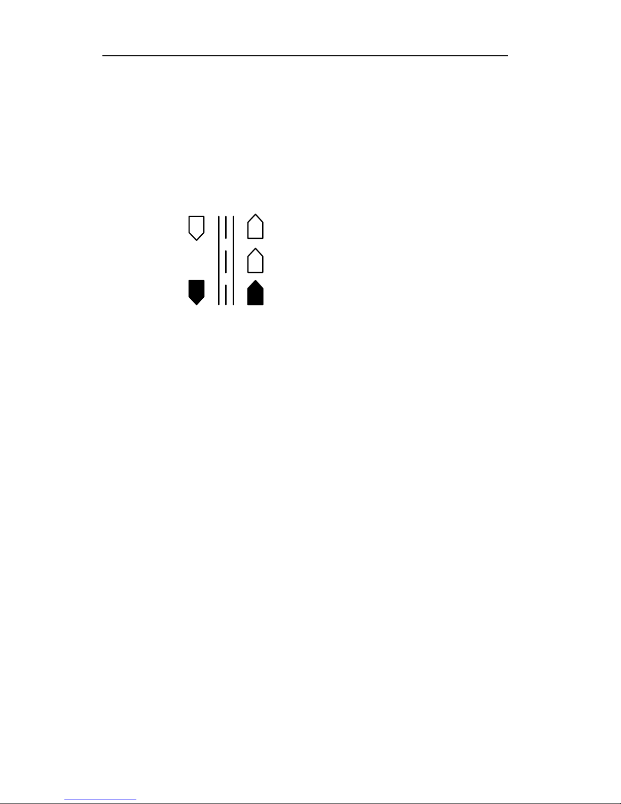
Road Graphic: These indicators are used to show
the mode of operation, target
direction, and selected antenna.
2.5
Page 12

Section 2--Specifications
Antenna:
Height:
2.52" (6.4 cm)
Width: 2.52" (6.4 cm)
Depth: 3.75" (9.5 cm)
Weight: 14 oz. (0.40 kg)
Microwave Source: Gunn Diode
Beam Width 12 degrees
Power Density: Less than 5 mW/cm2
Side Lobes: 25 dB below main lobe.
Polarization: Circular
Receiver: Low noise Schottky diode
direction conversion receiver.
Weather Resistant: For mounting inside or outside
vehicle.
__________________________________________________
2.6
Page 13

Section 3—Inspection & Mounting
3. INSPECTION AND MOUNTING
3.0 INITIAL INSPECTION
Before installing your Directional Golden Eagle II, please
take a moment to carefully inspect it for damage caused by
shipping. Contact the shipping carrier at once if you notice
any damage.
Remove the unit from the shipping carton and check the
packing list against your original purchase order. If the
shipment is incomplete or a parts error has been made,
please contact your district sales manager or Kustom
Signals Customer Service Department at (620) 431-2700 or
800-835-0156.
3.1 MATERIALS SUPPLIED
Description
The following equipment is normally included:
Wired remote control
Windshield Mount
Mounting Bail
30 MPH Tuning Fork
55 MPH Tuning Fork
Operator's Manual
Separation kit
Optional
Battery Pack and Charger
7 or 12-inch Dash Mount
Window Mount
Heavy Duty Carrying Case
Auxiliary Power Receptacle Cable
3.1
Page 14

Section 3—Inspection & Mounting
3.2 EQUIPMENT MOUNTING
3.2.1 AUXILIARY POWER RECEPTACLE
Cigarette lighter receptacles have been the traditional source
of power for traffic radar over the years. In the newer
vehicles, it is possible that poor grounding of this receptacle,
electrical noise from the vehicle's alternator charging
system, electrical fuel pump and microprocessor noise can
combine to create an unacceptably high level of ambient
electronic interference.
This interference can affect the radar's performance in
several ways: decreased range, no target speeds being
displayed or abnormal tones or noise in the audio.
Available for each Directional Golden Eagle II radar system
is an auxiliary power receptacle, which mounts under the
dashboard and wires directly to the battery.
1. Mount the receptacle in the desired location using the
hardware provided.
2. Connect the black wire to the receptacle's mounting
bracket. Connect the white wire (with Faston terminal)
to the rear plug of the receptacle. Route the cable
through the firewall and up to the battery.
3. Connect the white wire of the power cable to the battery
(+) positive terminal and the black wire to the
(-) negative terminal.
4. The Auxiliary power receptacle is supplied with a 2 amp
fuse to protect the battery should the cable become
shorted.
__________________________________________________
3.2
Page 15

Section 3—Inspection & Mounting
3.2.2 INDICATOR UNIT
CAUTION: Equipment mounted in 1994 and later series
police vehicles may interfere with the operation of
passenger side airbags. Please refer to the vehicle
manufacturer or your Kustom Signals District Manager for
additional information on safe mounting areas within the
vehicle.
1. The indicator unit consists of two components: the front
display panel, which contains the unit's displays and
switches, and the logic unit, which contains the main
circuit board. These two components can be mounted in
the vehicle as one piece or they can be separated and
mounted in different locations.
The Directional Golden Eagle II's display panel can be
located overhead, on the dashboard or on the radio rack.
The logic unit can be located under the dash, in the
glove box or under the front seat.
2. Locate mounting bail. Position the indicator for best
viewing position in the patrol vehicle and mark the
location for the mounting screws.
3. Drill a small pilot hole at the marked locations.
4. Set the bail bracket in place and secure to the dashboard
or other mounting location with mounting screws.
5. If the logic section is separated from the display,
consider mounting it in a convenient yet protected
location, i.e. under the dash, in the glove box or under
the front seat. The interconnect cable for the two
components attaches to the rear of the display panel and
front of the logic unit.
3.3
Page 16

Section 3—Inspection & Mounting
3.2.3 FRONT ANTENNA MOUNTING
Provided with the Directional Golden Eagle II is a
windshield mount for the antenna. Contact your District
Manager or Kustom Signals' Customer Service department
for other optional antenna mounts.
NOTE: Mounting of the antenna bracket to the dashboard
or any metal bracket (such as the radio rack) may
cause improper grounding of the antenna. This
would be noticed by reduced range and/or a high
pitched squeal in the audio. Use of the Kustom
Signals' isolation kit, P/N 050-0200-00 will
eliminate improper grounding.
1. Attach the antenna to the mount.
2. Connect the antenna to the Directional Golden Eagle II's
logic unit, front antenna port. Refer to Sec. 4.1 for
antenna port location.
3. Connect the Directional Golden Eagle II's power
connector to the proper power source. See Sec. 3.2.1.
4. Momentarily depress the POWER switch on the front
panel of the Directional Golden Eagle II (refer to Sec.
4.0 for location and function of front panel switches). It
will process through a lamp test and internal test as
described later in Sec. 6. Select Stationary mode ALL
by depressing the remote MODE switch until ALL is
displayed in the Patrol window. Both directional
indicators (front antenna) will be lit.
__________________________________________________
Stationary Mode
Front Antenna
3.4
Page 17

Section 3—Inspection & Mounting
5. Momentarily depress the AUDIO then the PAT-SET
switch. This places the Directional Golden Eagle II in
the unsquelched (audio on) mode. If necessary, depress
the AUDIO switch then the RANGE (up) switch to
increase the audio level.
6. Start the patrol vehicle and position the A/C - heater fan
to a mid-range speed. Move the antenna/mounting
bracket to different positions on the windshield while
listening to the audio. If there is fan interference, the
audio will have a raspy sound instead of just noise.
Position the antenna to minimize the amount of fan
interference. Mark this position on the outside of the
windshield, using a grease pencil.
7. After the optimum antenna position has been found, glue
the bracket to the windshield using the adhesive
provided.
8. Position of the antenna:
Stationary: Maximum performance of the
system will be achieved when
the antenna is pointed directly
toward the vehicles being
monitored.
Moving: Aim the antenna parallel to
the ground and straight down
the roadway.
3.5
Page 18
Section 3—Inspection & Mounting
3.2.4 REAR ANTENNA MOUNTING
1. Place the antenna on the rear-mounting bracket.
2. Follow the procedure for determining any fan
interference per Sec. 3.2.3, steps 4-6. Set the
Directional Golden Eagle II for stationary mode ALL,
rear antenna.
Stationary Mode
Rear Antenna
3. After the optimum position has been located (and marked
per Sec. 3.2.3 Step 6), permanently attach the mount to
the rear window using the adhesive provided.
4. Position the antenna cable behind the rear seat and under
the rear floorboard, then route up to the logic unit and
connect. This method of mounting will minimize the
antenna from moving around in the vehicle should it
break loose in an accident. It should also prevent
anyone from using the cable as a weapon against the
officer.
5. Position the antenna parallel to the ground and straight
down the roadway.
3.2.5 SPEEDOMETER PULSE CABLE
INSTALLATION
1. The speedometer pulse cable has a two-conductor plug
at one end and no plug at the other end. The plug
connects into the “SPDOMTR” connector on the rear
panel of the Directional Golden Eagle II.
__________________________________________________
3.6
Page 19

Section 3—Inspection & Mounting
2. The bare end of the speedometer pulse cable will be
connected to the patrol vehicle’s electrical speedometer
input cable using the splice connector provided. Due to
the vast number of models, makes, and years of vehicles
we have moved access to specific vehicle diagrams
online, where information can be better maintained and
distributed. Installation details can be accessed at:
http://www.kustomsignals.com
(select: radar fixed mount)
For information on connecting the Tru-Track cable
refer to the Kustom website above. For information
regarding motorcycle mounts refer to instructions in the
mount kits.
If your vehicle year, make and/or model is not listed or
you need hard copies, please contact Kustom’s
Customer Service Department at (800) 835-0156. If you
are outside of the US and Canada, please call (620) 431-
2700.
NOTE: Only the inner conductor of the speedometer pulse
cable is used. The outer shield is not connected.
3.7
Page 20
Section 4—Unit Description
4. UNIT DESCRIPTION
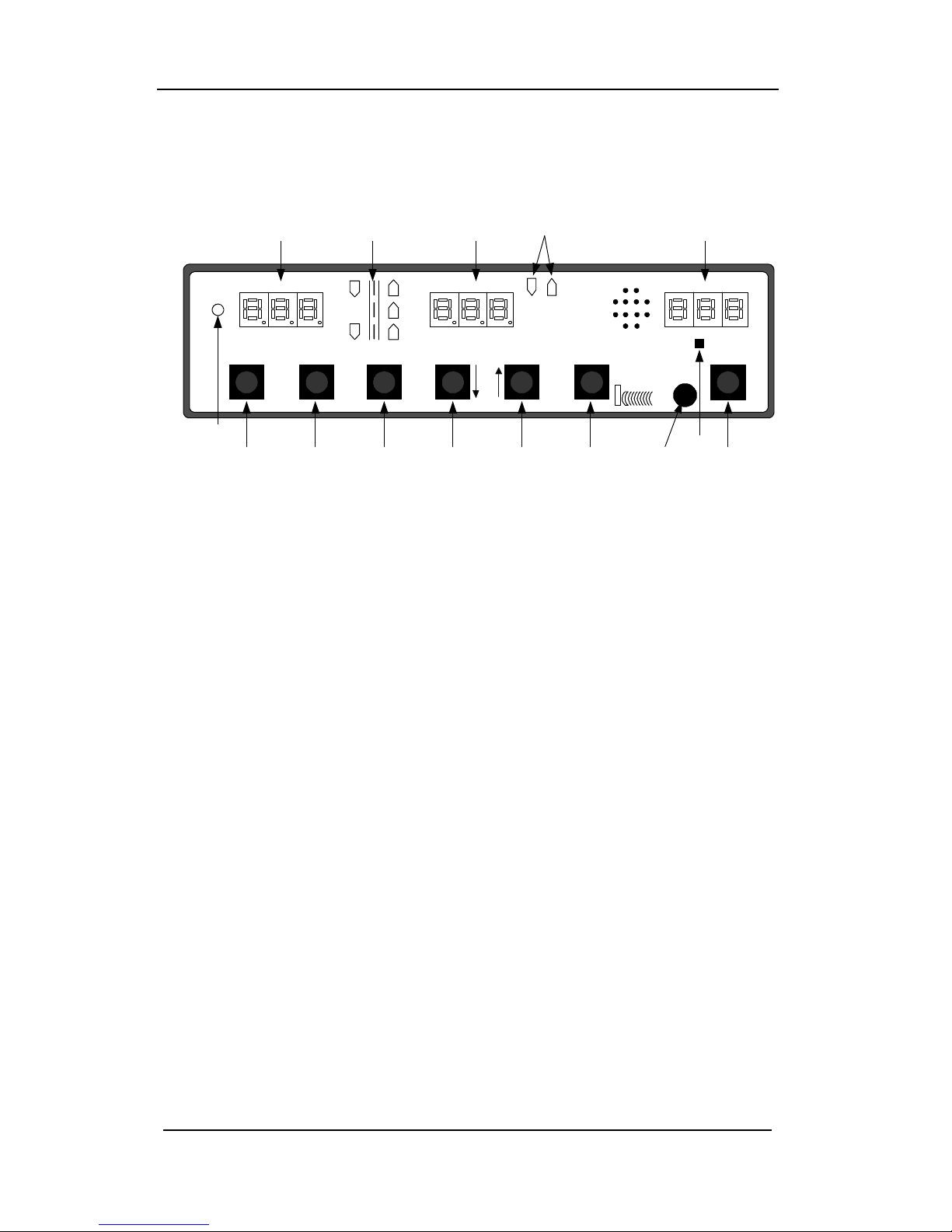
4.0 FRONT PANEL
A B C J D
LOCK/E.T.TARGET SPEED
LOCK-
REL
TEST AUDIO RANGE
PAT
SET
M
E F G H I K L
FASTEST PATROL SPEED/DIST.
STPW
KUSTOM SIGNALS, INC.
STPW/TEST
DIRECTIONAL
GOLDEN
EAGLE II
O
POWER
N
A. TARGET SPEED
Window
Displays the strongest speed of
target vehicles in both stationary
and moving modes. If a fastest
target is Locked, this display will
track the fastest speed. Displays
calculated target speed in
stopwatch mode.
B. Road Graphic Graphic indicates which antenna
is selected, the mode of
operation, and target direction.
C. LOCK/E.T.
Window
Displays locked target speeds. In
the stopwatch mode, displays the
elapsed time in seconds and
tenths seconds. In the Fastest
Mode, displays fastest speed.
D. PATROL SPEED
Window
Displays the speed of the patrol
vehicle. Displays the stationary
directional modes: ALL,
Receding only, or Approaching
only. In the stopwatch mode,
displays the distance to be used
for speed calculations.
4.1
Page 21

Section 4—Unit Description
E. LOCK/RELEASE
Switch
Switch used to lock and unlock
target and patrol vehicle speeds.
In the stopwatch mode, used to
start, stop and clear the timing
function.
F. TEST Switch Switch used to test the internal
accuracy and activate displays.
G. PAT-SET Switch In moving mode, pressing once
displays patrol minimum.
Pressing twice selects
speedometer sync. Secondary
functions—in locked mode,
activates or deactivates Patrol
Blank; with Audio switch
squelches or unsquelches audio;
with Range switch turns fan
interference filter on and off.
H. AUDIO (↓)
Switch
This switch used to set the audio
volume level. Secondary
function is the decrement (down)
control.
I. RANGE (↑)
Switch
Switch used to set range
sensitivity level. Secondary
function is the increment (up)
control.
J. FASTEST
Indicators
Lights when fastest vehicle mode
is active. Flashes when fastest
vehicle speed is being displayed.
K. STPW Switch This switch selects the Stopwatch
mode of operation.
L. POWER Switch Switch control for power-on / off.
__________________________________________________
4.2
Page 22

Section 4—Unit Description
M. Ambient Light
Detector
Detects ambient light conditions
and adjusts the brightness of
displays automatically.
N. STPW/TEST
Indicator
On solid indicates in stopwatch
mode. Flashing indicates in test
mode.
O. IR Window Infrared wireless control window.
4.3
Page 23
Section 4—Unit Description
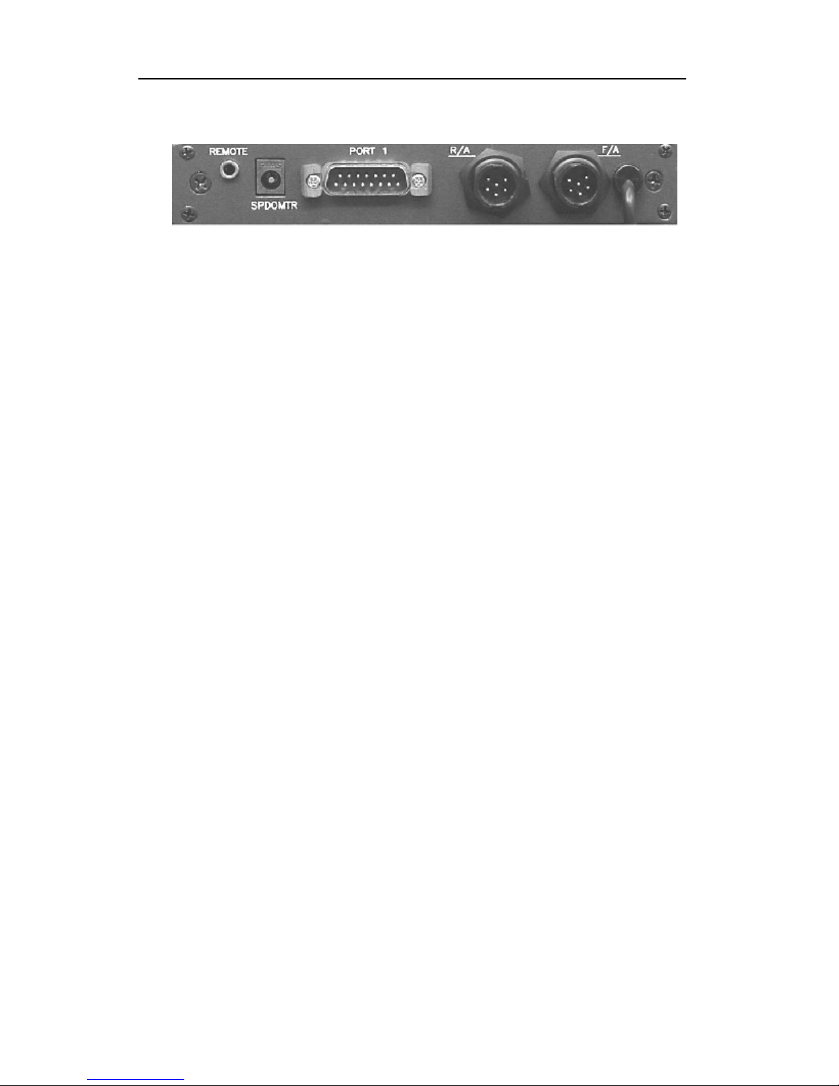
4.1 REAR PANEL
The rear panel of the Directional Golden Eagle II has
connectors for two antennas, remote control, RS232 I/O port
and Speedometer input cable. In addition, there is a captive
power cord attached to the rear panel.
Located on the left side of the rear panel is a 3.5 mm
connector for the external remote control. This connector is
used for the wired remote control.
Next to the remote control connector is the Speedometer
Input Cable connector. This cable attaches to the vehicle’s
speed sensor to assist the DSP to process proper patrol
speed.
PORT 1 interfaces to a Kustom Signals Eyewitness® in-car
video system or Giant Display. This port provides speed
and status information to external devices.
The two antenna connectors are marked “R/A” (Rear
Antenna) and “F/A” (Front Antenna). Ensure the antenna
cable(s) are connected to the correct location.
The power cord is permanently attached to the logic unit. It
supplies power to the system from the patrol vehicle's
cigarette lighter receptacle, auxiliary power receptacle or
portable battery pack. The power input is reverse polarity
protected and protected from over-voltage and over-current
conditions.
__________________________________________________
4.4
Page 24

RELEASE
Section 4—Unit Description
4.2 REMOTE CONTROL
LOCK
REL
A
FAST
HOLD
B
SAME
OPP
C D
FRNT
REAR
E
DIRECTIONAL
GOLDEN
EAGLE II
MODE
F
KUSTOM SIGNALS, INC.
The remote control plugs directly into the back panel's
remote jack.
A. LOCK-
(Start-Stop-Clear
in stopwatch
This pushbutton switch is used for
locking and releasing target and
patrol speeds. In the stopwatch
mode this button will start, stop
mode).
and clear the timer.
B. HOLD
This switch is used to turn the
microwave transmitter on and off.
4.5
Page 25

Section 4—Unit Description
C. FAST
This switch is used to activate
fastest target vehicle mode.
Fastest can be operated in one of
two methods. See Sec. 14.1.4 for
details on setting options.
D. SAME/
OPPOSITE
In moving mode this switch selects
either the same direction or
opposite direction mode.
In stationary receding only or
approaching only, this switch
toggles between directions.
E. FRONT/REAR
Switches the active antenna
between the front or rear.
F. MODE
Cycles the unit through the four
modes of operation.
1. Moving Mode.
2. Stationary ALL.
3. Stationary Approaching
only.
4. Stationary Receding only.
__________________________________________________
4.6
Page 26

Section 5—General Theory of Operation
5. GENERAL THEORY OF OPERATION
5.0 GENERAL
The Directional Golden Eagle II moving radar system
transmits a Ka-Band radio frequency in compliance with the
Federal Communications Commission (FCC) regulations.
A portion of the transmitted signal strikes the surface of the
roadway and surrounding terrain and reflects back to the
antenna. The returning signal is the "groundspeed"
Doppler. From the antenna, it travels to the Digital Signal
Processing (DSP) where the signal is translated to the speed
of the patrol vehicle (groundspeed) and is displayed in the
PATROL display.
The Eagle II series has an exclusive feature from Kustom
Signals using the patrol vehicle’s speed sensor pulses,
which steers the DSP processor to look for the
“groundspeed” Doppler signal in a specific speed range.
This feature will eliminate the often-annoying anomalies
such as shadowing, combined patrol speeds, splitting
speeds, and displaying speeds in the PATROL window
when stopped at a traffic light or sign.
In moving opposite direction mode, a portion of the
transmitted signal strikes an oncoming vehicle (target
vehicle) and returns a Doppler frequency higher than the
groundspeed because the two objects (patrol vehicle and
target vehicle) are converging. This returning signal is the
"target" Doppler. The counting unit measures this speed of
convergence, or combined speed.
Upon receiving the "target" Doppler signal, the counting
unit automatically computes the difference between the
speed of the patrol vehicle and the target vehicle. The speed
of the approaching vehicle registers in the TARGET
display. If, for example, a patrol vehicle is traveling 55
MPH and an approaching vehicle is traveling 65 MPH, the
Directional Golden Eagle II would process the groundspeed
of 55 MPH and the combined speed of 120 MPH. The DSP
would subtract the patrol speed from the combined
5.1
Page 27

Section 5—General Theory of Operation
speed (120 - 55 = 65). The PATROL display would
indicate 55 and the TARGET display would indicate 65.
In the Moving Same Direction mode of operation, the target
Doppler is received from a target traveling in the same
direction as the patrol vehicle. These "groundspeed"
Doppler and the "difference" Doppler signals are received
and sent to the DSP. The Difference Doppler is the speed
difference between the patrol vehicle and a vehicle traveling
in the same direction. The Directional Golden Eagle II uses
its directional determination capabilities to automatically
determine if the target vehicle is traveling faster or slower
than the patrol vehicle. The unit will display the patrol
speed then automatically add or subtract the "difference"
speed to the patrol speed for the target speed.
If the patrol vehicle's speed was 55 mph and a target was
traveling in the same direction at 70 mph, the Directional
Golden Eagle II would display 55 in the PATROL display
then add the "difference” Doppler signal 15 to the PATROL
display (55 + 15 = 70) and display 70 in the TARGET
window.
__________________________________________________
5.2
Page 28

Section 5—General Theory of Operation
5.1 MICROWAVE RF EMISSIONS
Traffic radar operators may have some questions about the
biological effects of exposure to the microwave energy
produced by the radar devices. According to all credible
evidence, the emission levels resulting from traffic radar use
pose no threat whatsoever, either to the radar operator or to
target vehicle occupants.
One widely recognized authority for safe limits of
nonionizing radiation exposure is the American National
Standards Institute, which recommends maximum exposure
levels for the frequencies on which Kustom traffic radar
systems operate (ANSI/IEEE C95.1-1999, "Standard for
Safety Levels With Respect to Human Exposure to Radio
Frequency Electromagnetic Fields, 3 kHz to 300 GHz").
These exposure levels, expressed in terms of power density,
are 7 mW/cm2 for X-band radar units, and 10 mW/cm2 for
K-band and Ka-band radar units. Similarly, the
Occupational Safety and Health Administration (OSHA), a
division of the U.S. Department of Labor, recommends a 10
mW/cm2 exposure limit for all three frequency bands
("Radiation Protection Guide", 29 CFR, Chapter XVII,
Subpart G, Part 1910.97). This limit is clearly accepted by
most reputable scientific and medical authorities.
Kustom radar systems utilize microwave transmitters which
produce aperture power densities, measured directly at the
face of the antenna, in the range of approximately 0.3 to 2.3
mW/cm2. Typical levels for the vast majority of units are in
the 0.4 to 1.0 mW/cm2 range, which is but a small fraction
of the recognized safe limits. Bear in mind that these are
level measurements taken directly in the main beam of the
antenna, and that the power densities produced at the sides
and rear of the unit are typically at least one hundred times
lower than in the main beam.
5.3
Page 29

Section 5—General Theory of Operation
Another reference document on this topic is a DOT
publication entitled "Field Strength Measurements of Speed
Measuring Radar Units" (NHTSA Technical Report #DOTHS-805 928). This report documents a series of tests
performed by the National Bureau of Standards on twentytwo commonly used models of traffic radar units, from six
different manufacturers including Kustom. Aperture power
density levels measured were from 0.25 to 2.82 mW/cm2,
while back-lobe power density values ranged from 0.001 to
0.02 mW/cm2. These measurements were obtained with the
radars mounted inside vehicles, as in normal operating
conditions. Since the NBS study, other laboratories have
duplicated these types of measurements, producing
consistently similar results.
For a free copy of the latest information regarding the safe
human exposure standards, please call or write Kustom to
request the "RF Emissions Packet." You may contact us at
our corporate headquarters:
Kustom Signals, Inc.
9325 Pflumm
Lenexa, KS 66215-3347
(913) 492-1400
While traffic radar devices do emit microwave energy, the
levels are so low that there are no probable harmful effects.
You may use your Kustom radar unit with complete
confidence in its safety, as well as in its accuracy.
__________________________________________________
5.4
Page 30

Section 6—Testing Procedures
6. TESTING PROCEDURES
6.0 GENERAL
The internal test and tuning fork tests explained below
should be conducted at the beginning and end of each patrol
shift to ensure the accuracy and functionality of the unit.
The results of these tests may be recorded in a radar log,
similar to the log found at the end of this manual.
6.1 POWER ON
Momentarily depress the POWER switch. The unit will
display all LED display segments (888) and turn on all
lamps and indicators on the front panel. After
approximately 1 second, the unit will perform several
internal circuitry tests and a crystal cross check to verify the
accuracy of the speed processing circuitry.
If these pass successfully, the unit will display "PAS" in the
TARGET display (stationary operation) or both the
TARGET and PATROL displays if the unit is in the moving
mode of operation. This will remain for approximately 1
second. The current audio level will then be displayed,
indicated by "Aud" in the TARGET window and the
PATROL window will display the audio volume level
selected (0 - 9). The audio will be un-squelched during this
state, so the volume level can be heard in the speaker.
One second later, "rnG" will be displayed in the TARGET
window and the PATROL window will display the current
range level (0 - 6). (The higher the range setting, the more
sensitive the target captures.) After another second, the
displays will clear and the unit will be operational in the
same mode that it was in when the unit was shut off.
6.1
Page 31

Section 6—Testing Procedures
6.2 AUTOMATIC SELF-TEST
The Directional Golden Eagle II performs an internal
accuracy test whenever the unit's mode of operation is
changed, the target speed is locked, or upon the lapse of a
maximum time period of 5 minutes, as long as the unit is
powered up. In addition, this self-test will be initiated at the
end of each timing cycle in the stopwatch mode.
This test is automatic and will not interfere with any radar
speed-readings being taken. The test does not appear in the
displays, but if an error is detected during this test, the
TARGET display will indicate “Err” and further speedreadings will be inhibited.
6.3 MANUAL TEST
The operator can depress the TEST switch at any time
during normal radar operation to perform the lamp and
internal tests as described in Sec. 6.4. If the Directional
Golden Eagle II is in the Stopwatch Mode and a timing
cycle is in process, the test switch is inoperative until the
timing cycle has ended.
NOTE: The audio and range indications will not be
displayed during a manual test.
6.4 ACCURACY TESTING
Depress the MODE switch, if necessary, to place the
Directional Golden Eagle II in the stationary ALL mode of
operation (both direction indicators on).
__________________________________________________
6.2
Page 32

Section 6—Testing Procedures
Momentarily depress the TEST switch. Holding the TEST
switch depressed will light all displays. Upon releasing this
switch, the Directional Golden Eagle II will complete the
internal tests. If these tests pass, the TARGET window will
display "PAS" in the TARGET window. If the TEST button
is held depressed for greater than 10 seconds, the internal
test will proceed as a default condition.
NOTE: The unit will remain in the TEST state for 30
seconds after releasing the TEST switch, indicated
by the flashing STPW/TEST LED. Due to the
ability of the unit to reject non directional signals,
the operator must place the unit in this TEST mode
to read tuning forks. (See Sec. 6.5).
Depress the MODE switch to place the unit in the moving
mode, opposite direction. Depress the remote control
OPPOSITE/SAME switch if necessary. The opposite
direction road graphic indicator will be lit.
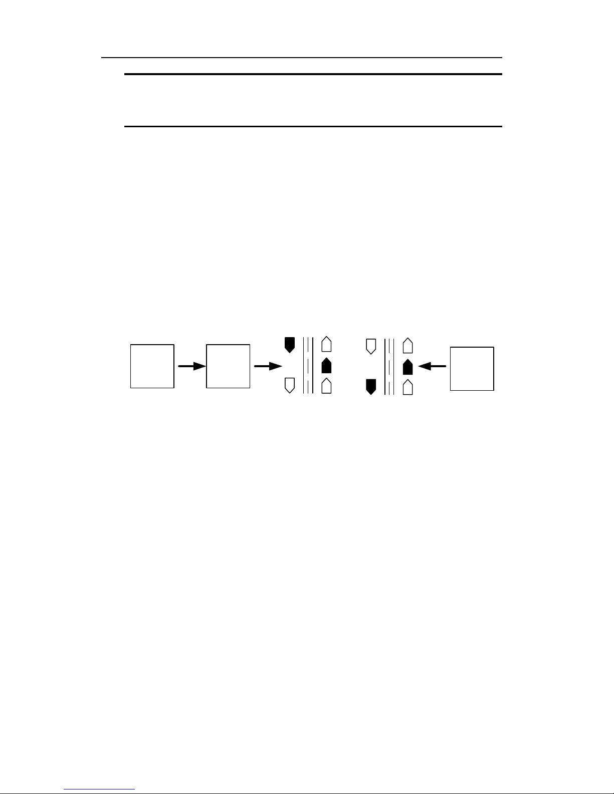
Select
Moving
Select
Opposite
Select
Antenna
MODE
SAME
OPP
or
FRNT
REAR
Momentarily depress the TEST switch. If the system is
working properly, the unit will proceed through the lamp
and internal tests as described above.
Internal test tolerance: + 0.
6.5 TUNING FORK TESTING
Supplied with the Directional Golden Eagle II are two
tuning forks, 30 and 55 MPH. These tuning forks will
simulate moving vehicles in the stationary or moving
modes.
6.3
Page 33

Section 6—Testing Procedures
The tuning fork tests should be conducted in an area with no
traffic. If this is not possible, point the antenna away from
moving vehicles to avoid reflections.
Tuning fork test tolerance: + 1 MPH (1 km/h).
** Due to the ability of the Directional Golden Eagle II
to reject non-directional signals, the operator must place
the unit in the TEST mode to read tuning forks.
Momentarily depress the TEST switch. Upon releasing
this switch, the Directional Golden Eagle II will
complete the internal tests and enter the tuning fork
TEST mode.
NOTE: The unit will remain in the TEST mode for 30
seconds after releasing the TEST switch, indicated
by the flashing STPW/TEST LED. Tuning fork
tests may be performed while in this mode.
Changing to a new mode will refresh the timeout to
30 seconds, allowing fork testing in different
modes without leaving the TEST mode. Pressing
the TEST switch again, while in the TEST mode
will exit the TEST mode immediately.
6.5.1 STATIONARY & OPPOSITE DIRECTION
MOVING MODES
1. Press the MODE switch until the Directional Golden
Eagle II is in the stationary ALL mode (ALL in the
PATROL window and both directional road graphic
indicators should be lit). Use the remote control to
change to the desired antenna. If the unit is displaying
"Hld" in the TARGET window, depress the HOLD
switch to place the unit in a transmitting mode.
Select
ALL
MODE
or
Select
Antenna
FRNT
REAR
__________________________________________________
6.4
Page 34

Section 6—Testing Procedures
2. Depress and hold the RANGE (up) switch until 6 is
displayed in the PATROL window (maximum range).
After releasing the RANGE switch, the "rnG" display
will remain for 2 seconds then the displays will return to
normal operation.
3. Momentarily press the TEST switch to enter the TEST
mode. The STPW/TEST indictor will be flashing while
in the TEST state.
4. Lightly strike the lower speed (30 MPH or 45 km/h)
tuning fork on a hard, non-metallic surface. Place and
hold the tuning fork approximately 1 inch in front of the
antenna.
5. Verify that the TARGET speed displays the same speed
as the tuning fork (30 or 45).
6. Repeat steps 3 and 4 using the higher speed (55 MPH or
80 km/h) tuning fork. The TARGET speed display
should indicate the same speed as the tuning fork (55 or
80).
NOTE: Since the Directional Golden Eagle II can
determine these fork signals are not moving
targets, the speeds displayed as a result of the fork
tests cannot be LOCKED.
7. Depress the MODE switch until the Directional Golden
Eagle II is in the moving mode. Use the SAME OPP
switch to select opposite direction, if not already in that
mode. Use the FRONT REAR switch to select the
proper antenna. Only the patrol LED and opposite
direction LED indicator will be lit on the road graphic.
If not still in the TEST state, depress the TEST switch to
restart the time for the TEST state to tuning fork testing.
6.5
Page 35

Select
Section 6—Testing Procedures
Select
Moving
Select
Opposite
Select
Antenna
MODE
SAME
OPP
or
FRNT
REAR
8. Lightly strike the lower speed tuning fork on a hard, non-
metallic surface. Place it approximately 1 inch in front
of the antenna. Verify that the patrol speed displayed is
the same as the speed stamped on the fork. While
holding the lower speed tuning fork in front of the
antenna, lightly strike the higher speed tuning fork on a
hard, non-metallic surface and place it in front of the
antenna at the same time.
The TARGET speed display should read the difference
of the two forks. Example: closing speed, 55, minus
patrol speed, 30, equals 25. (80 km/h minus 45 km/h
equals 35 km/h).
6.5.2 SAME DIRECTION TUNING FORK TEST
1. With the Directional Golden Eagle II in the moving
mode, depress the Opposite/Same switch on the remote
control, placing the unit in the Same-Direction mode.
Use the FRONT REAR switch to select the proper
antenna.
Select
Moving
MODE
Same
Direction
SAME
OPP
Antenna
or
REAR
If not still in the TEST mode, depress the TEST switch
to restart the time for the TEST mode to allow tuning
fork testing.
Select
FRNT
__________________________________________________
6.6
Page 36

Section 6—Testing Procedures
2. Lightly strike the higher of the two tuning forks, 55
MPH, on a hard, non-metallic surface, and place it 1
inch in front of the antenna. Verify that the PATROL
display indicates 55.
3. While holding the higher tuning fork in front of the
antenna, lightly strike the lower tuning fork, 30 MPH,
on a hard, non-metallic surface, and place it
approximately 2 inches in front of the antenna. Observe
the TARGET display and verify a reading that is the
sum of the two forks. (Patrol speed, 55, plus opening
speed, 30, equals 85).
NOTE: Since striking a tuning fork too hard may cause
harmonic oscillations that will be picked up by the
fan interference filter, blanking all speed-readings,
it is recommended that the operator momentarily
turn the filter "OFF" during this test. (These tests
can be performed with the filter on if the tuning
forks are lightly struck.) If the fan filter is
normally used, remember to reset the filter to the
FAN "ON" mode after the tuning fork tests have
been completed.
6.5.3 TUNING FORK TEST FAILURE
If proper speed-readings are not obtained during the
previous tests, check the following:
1. Verify that the tuning forks are the proper tuning forks
supplied with the unit.
2. Striking the tuning forks too hard or on a metallic surface
will cause spurious overtones from the tuning forks.
This may cause the speed-readings to be slightly higher
than specified. These readings are only momentary and
the proper readings should appear as the false overtones
dissipate.
6.7
Page 37

Section 6—Testing Procedures
NOTE: Do not move the tuning forks after they have been
placed in front of the antenna.
3. Ensure that the Directional Golden Eagle II is not in the
HOLD mode and that the RANGE control is at level 6.
If the proper readings cannot be obtained, remove the unit
from service and send to an authorized service center for
repair.
6.6 MOVING MODE TEST
Verification of speed-readings between the patrol vehicle's
speedometer and the Directional Golden Eagle II's
PATROL speed display is another accuracy test that can be
performed. These readings should be the same, or within
reasonable limits, allowing for minor speedometer error.
Speedometer checks should be done on a daily basis. If a
discrepancy is found, the radar unit should be removed from
service until the error can be corrected.
__________________________________________________
6.8
Page 38

Section 6—Testing Procedures
6.7 SPEEDOMETER INPUT SYNCHRONIZATION
The initial use of the Directional Golden Eagle II with
speedometer pulse input requires the radar unit to be
synchronized with the speedometer.
1. After installation and initial testing with tuning forks,
the Directional Golden Eagle II should be driven at a
constant speed between 30 and 70 MPH (48 and 112
km/h). Depress the PAT-SET switch on the front panel
twice. “Snc” will appear in the TARGET window and
Doppler patrol speed will appear in the PATROL
window.
2. Verify the patrol speedometer and the Doppler patrol
speed displayed agree within reasonable limits, and then
depress and release the Lock/Release switch. This tells
the DSP processor that the current speedometer pulses
(speed) and the Doppler patrol signal (radar patrol
speed) agree.
After approximately one second, a number will briefly
appear in the LOCK window. For Ford Motor Company
vehicles, this synchronization number will be around 34.
This indicates the unit is reading and comparing the
speedometer pulses and the Doppler patrol signal.
NOTE: Only the actual radar Doppler signal is used
for patrol speed. The speedometer pulse input
is used only to steer or guide the DSP to “look”
for the patrol Doppler signal in a specific area,
ignoring other signals.
6.9
Page 39

Section 6—Testing Procedures
3. During normal operation, at patrol speeds below the
minimum limit, or when a patrol Doppler signal cannot
be found, the PATROL window will display two dashes,
indicating that speedometer pulses are being received,
but a patrol speed cannot be displayed. If, for example,
a patrol vehicle is traveling at 50 MPH (80 km/h) by the
speedometer but the DSP cannot find any patrol Doppler
signal around that speed, two dashes will be displayed in
the PATROL window and no target speeds will be
displayed.
__________________________________________________
6.10
Page 40

Section 7—System Operation
7. SYSTEM OPERATION
7.0 OPERATING MODES
The Directional Golden Eagle II is designed to be the most
complete radar system ever developed for law enforcement
use. It has 11 different operating modes:
1. Stationary ALL Front Antenna
2. Stationary ALL Rear Antenna
3. Stationary Approaching Only Front Antenna
4. Stationary Approaching Only Rear Antenna
5. Stationary Receding Only Front Antenna
6. Stationary Receding Only Rear Antenna
7. Moving Opposite Direction Front Antenna
8. Moving Opposite Direction Rear Antenna
9. Moving Same Direction Front Antenna
10. Moving Same Direction Rear Antenna
11. Stopwatch
This provides the operator complete coverage in all traffic
situations.
In the stationary mode, the Directional Golden Eagle II
obtains speeds of target vehicles traveling in either
direction. In the moving mode, it can obtain speeds of
vehicles approaching the patrol vehicle from an opposite
direction, receding from the patrol vehicle (in the opposite
direction), speeds of vehicles traveling in the same direction
as the patrol vehicle, either in front of or behind the patrol
vehicle.
The Directional Golden Eagle II's stopwatch mode
calculates the speed of vehicles traveling between two
marks using time and distance.
7.1
Page 41

Section 7—System Operation
NOTE: The following guide to operating the Directional
Golden Eagle II radar system is not intended to be
a training program. Before operating this unit or
any other traffic radar system, Kustom Signals
urges all operators to have prior training in radar
speed monitoring devices. Such courses are
offered by Kustom Signals, various state and local
agencies and either IPTM (Institute of Police
Technology and Management) or Northwestern
University. Contact your District Manager for
further details.
7.1 SETUP
1. Select a location that provides a good view of the traffic
to be monitored.
2. Check the immediate area for potential interference
sources, such as large reflecting signs in the direct path
of the radar's microwave beam, power substations and
other sources of electrical interference.
3. Position the patrol vehicle in a safe location, with easy
access to the roadway.
NOTE: Cosine effect (angle between the target's direction
of travel vs. the path to the radar), in the stationary
mode, will ALWAYS be in the driver's favor.
Refer to the National Highway Traffic Safety
Administration's "Basic Training Program in
RADAR Speed Measurement" for speed reduction
information due to cosine angle effect.
__________________________________________________
7.2
Page 42

Section 7—System Operation
4. Adjust the Doppler audio for the desired listening level.
Depress the AUDIO switch. The TARGET window
will display "Aud" and the PATROL window will
display the current audio level.
With "Aud" still being displayed, depress either the
AUDIO (down) or RANGE (up) switches to decrease or
increase the audio level. The displays will return to their
normal mode two seconds from the last switch entry or
momentarily depress the HOLD switch to return to
normal operation immediately.
5. To unsquelch the audio, depress the AUDIO switch. The
TARGET window will display "Aud". Depress the
PAT-SET switch. The LOCK/E.T. window will display
"Un".
To return to squelched audio, with "Aud" and "Un"
being displayed, again depress the PAT-SET switch.
The LOCK/E.T. window will be blank and the audio
will be squelched. Two seconds after the last switch
entry, the displays will return to their normal functions
or momentarily depress the HOLD switch to return to
normal operation immediately.
6. Set the range control to the desired level. Depress the
RANGE switch and the TARGET window will display
"rnG" and the PATROL window will display the current
level (1 - 6). Range level 6 is maximum range; range
level 1 reduces the Directional Golden Eagle II's range
to its minimum distance, typically 250 feet.
Depressing the DOWN (AUDIO) or UP (RANGE)
switches will decrease or increase the range level. The
displays will return to their normal mode after
approximately two seconds from the last switch entry or
momentarily depress the HOLD switch to return to
normal operation immediately.
7.3
Page 43

Section 7—System Operation
7. Check the status of the fan interference filter by
momentarily depressing the RANGE switch. While
"rnG" is being displayed, depress the PAT-SET switch
to display "FAn" in the TARGET window and either
"On" or "OFF" in the LOCK window. Press PAT-SET
again to change the status of the filter. The operator
may activate or deactivate this filter depending on the
amount of fan interference being experienced in a
particular patrol vehicle. If the fan is interfering with
radar operation, activating the filter will reduce the
amount of fan interference.
NOTE: The fan interference filter is operational in Same
Direction Mode only.
The displays will return to their normal mode
approximately two seconds from the last switch entry or
momentarily depress the HOLD switch to return to
normal operation immediately.
NOTE: Some degradation of target capture may be noted
with the filter activated. For maximum
performance, if the patrol vehicle has little or no
fan interference, it is suggested that the fan
interference filter be turned off.
__________________________________________________
7.4
Page 44

Section 7—System Operation
7.2 STATIONARY OPERATION
1. Place the unit in the stationary ALL mode. Switch to
the desired antenna. Set range to the desired level.
(Level 1, target must be very close before the unit will
display the target's speed, Level 6, maximum range.)
Select
ALL
Select
Antenna
MODE
or
FRNT
REAR
*2. If desired, turn the microwave transmitter off by
depressing the remote control HOLD switch. "Hld" will
be displayed in the TARGET window.
3. Complete a tracking history on the target vehicle.
A. Observe the target and surrounding traffic.
B. Estimate the speed of the target vehicle.
*C. Depress the HOLD switch to turn the microwave
transmitter on.
D. Listen to the pitch of the audio; it should correspond
to the estimated speed.
E. Observe the speed-reading shown in the Directional
Golden Eagle II's TARGET display. It should
correspond with B and D above.
F. Observe the indication of the target's direction of
travel from the road graphics indicator. It should
correspond to the observed target's direction of
travel.
G. If any of the above elements are incompatible, the
reading must be disregarded.
* Use the HOLD feature to defeat radar detectors.
7.5
Page 45

Section 7—System Operation
4. If the operator wishes to lock (retain) the violator's
speed, simply depress the LOCK switch on either the
front panel or the remote control. A short alert tone will
be heard and the target speed will be displayed in the
LOCK window.
5. The Directional Golden Eagle II will continue to track
the violator's speed in the TARGET window as long as
the vehicle is in the antenna beam.
6. If the operator switches to the opposite antenna, the road
graphic indicator for the selected antenna at the time of
lock will flash and the selected antenna will be on. If
the operator changes back to the original antenna, the
original antenna indicator will light steady.
NOTE: If the auto-unlock feature is enabled, the locked
speed will be automatically unlocked after 14
minutes.
The Directional Golden Eagle II will automatically run
an internal test prior to locking any speed. Depressing
the TEST switch will allow the Directional Golden
Eagle II to complete a lamp and internal test then return
the locked speed.
7. To manually unlock or clear the locked speed depress the
LOCK/REL switch. This will clear the LOCK/E.T.
window.
8. If the operator changes the mode of operation, such as
stationary to moving, the locked speed will be
automatically unlocked and cannot be recalled.
__________________________________________________
7.6
Page 46

Section 7—System Operation
7.2.1 FASTEST VEHICLE--STATIONARY
OPERATION
1. The Directional Golden Eagle II allows two methods of
fastest vehicle mode (Push and Hold control or Toggle
control). See Sec. 14.1.4 for selecting the preferred
method. When the fastest mode is activated, the
FASTEST directional LEDs will indicate the direction
being searched for fastest vehicle.
2. When a fastest vehicle is detected the FASTEST
directional LED will flash according to the direction the
fastest vehicle is traveling and the LOCK/E.T. window
will display the speed of the fastest vehicle. (The
TARGET window will continue to display the speed of
the strongest target vehicle.)
NOTE: This is especially useful in traffic situations such
as a small vehicle overtaking a larger truck. In the
FASTEST mode, as in normal radar operation, a
good tracking history is essential.
3. The operator may lock the fastest speed by depressing
the LOCK switch while a fastest speed is displayed.
The strongest speed may be locked by depressing the
LOCK switch when only the strongest speed (no fastest
speed) is being displayed.
4. When the speed is locked, a short alert tone will be
heard. If the fastest vehicle's speed was locked, the
TARGET window will display the current fastest target
(for track-through-lock history), and the FASTEST LED
will continue to flash, indicating the locked speed was
obtained as a fastest speed. If the strongest vehicle
speed was locked, the TARGET window will continue
to show the strongest target and the fastest indicator will
be turned off, indicating the locked speed was obtained
as a strongest speed.
7.7
Page 47
Section 7—System Operation
NOTE: If the auto-unlock feature is enabled, the locked
speed will be automatically unlocked after 14
minutes.
7.3 MOVING OPERATION (OPPOSITE
DIRECTION)
1. Place the Directional Golden Eagle II in the moving
mode of operation by depressing the MODE switch until
reaching the moving mode as observed by the road
graphic indicators. The patrol and an opposite direction
indicator should be lit. If a same direction indicator is
on, depress the SAME/OPP switch on the remote
control.
Select
Moving
Select
Opposite
Select
Antenna
MODE
SAME
OPP
or
FRNT
REAR
2. Select the desired antenna, front or rear by depressing the
FRONT/REAR switch on the remote control.
3. Set the minimum patrol speed to the desired level--10 or
20 MPH (16 or 32 km/h). To activate this feature once
the unit has been placed in Moving Mode, press the
PAT-SET switch once. The TARGET window will
display “PAt” and either 10 or 20 will appear in the
PATROL window. This display will be active for two
(2) seconds unless another switch is pressed. To change
the displayed minimum speed, press either of the UP or
DOWN switches, which will toggle between the two
speeds.
__________________________________________________
7.8
Page 48

Section 7—System Operation
Once the desired minimum speed is selected, the display
will time out in two seconds and the last displayed speed
will be accepted as patrol minimum. This feature cannot
be activated with a locked speed in the LOCK window.
To display the minimum patrol speed, press the PATSET switch once. Any currently active displays will be
replaced with the selected minimum patrol speed for two
seconds, then the Directional Golden Eagle II will return
to normal operation.
NOTE: This feature cannot be activated with a locked
speed in the LOCK window.
4. Complete a tracking history on a target vehicle as
described in Sec. 7.2 Step 3 and verify the radar's patrol
speed-reading with the patrol vehicle's speedometer.
NOTE: If an incorrect patrol speed is obtained, the operator
can go in and out of HOLD quickly. This will
clear all previous speeds, and a new patrol speed
search will be initiated.
5. When all elements agree, enforcement action may be
taken.
6. To lock the violator's speed, depress the LOCK switch.
A short alert tone will be heard and the LOCK window
will display the speed of the target vehicle.
7. The Directional Golden Eagle II will continue to track
the target and patrol speeds.
7.9
Page 49

Section 7—System Operation
8. When the patrol vehicle's speed has dropped 10 MPH (16
km/h) or more below the speed when lock was activated,
or the antenna selection is changed, the patrol vehicle's
speed, at the time of lock, will begin flashing in the
PATROL window.
NOTE: This allows the operator to continue to track the
target while monitoring the patrol vehicle's speed
and still retain the locked patrol speed.
9. The operator may blank the locked PATROL speed
display window, during lock, by depressing the PATSET switch. Depressing the switch again will return the
locked PATROL display.
10. To manually unlock or clear the locked speeds, depress
the LOCK/REL switch. This will clear the LOCK/E.T.
and the locked PATROL windows.
NOTE: If the auto-unlock feature is enabled, the locked
speeds will be automatically unlocked after 14
minutes.
11. If the operator changes the mode of operation, such as
moving to stationary, opposite to same direction, etc.,
the locked speeds will be automatically unlocked and
cannot be recalled.
Depressing the TEST switch will allow the Directional
Golden Eagle II to complete a lamp and internal test
then return the locked speed.
If the antenna was changed to track the target vehicle
after it passed the patrol vehicle, the road graphic
indicators will flash the antenna selected at the time of
lock. All locked speeds will be retained.
__________________________________________________
7.10
Page 50

Section 7—System Operation
7.3.1 FASTEST VEHICLE--MOVING OPPOSITE
1. Set up system as in Sec. 7.3, steps 1-4.
2. The Directional Golden Eagle II allows two methods of
fastest vehicle mode (Push and Hold control or Toggle
control). See the section for setting Options (Sec.
14.1.4) for selecting the preferred method. When the
fastest mode is activated, the FASTEST directional
LEDs will indicate the direction being searched for
fastest vehicle.
NOTE: This is especially useful in traffic situations such
as a small vehicle overtaking a larger truck.
In the FASTEST mode, as in normal radar
operation, a good tracking history is essential.
3. When a fastest target is detected, the directional
FASTEST LED will flash and the LOCK/E.T. window
will display the speed of the fastest vehicle. (The
TARGET window will continue to display the speed of
the strongest target.)
4. Refer to Sec. 7.3, steps 5-7 for the procedure for locking
the target vehicle speed.
5. If the fastest vehicle speed was locked, the TARGET
window will display the current fastest target (for trackthrough-lock history), and the FASTEST LED will
continue to flash, indicating the locked speed was
obtained as a fastest speed. If the strongest vehicle
speed was locked, the TARGET window will continue
to show the strongest target and the fastest indicator will
be turned off, indicating the locked speed was obtained
as a strongest speed.
7.11
Page 51

Select
Section 7—System Operation
7.4 MOVING OPERATION (SAME DIRECTION)
1. Place the Directional Golden Eagle II in the moving
mode of operation by depressing the MODE switch until
reaching the moving mode as observed by the road
graphic indicators. Select SAME operation by
depressing the SAME/OPP switch on the remote
control. Verify that the road graphic indicators for same
direction are lit. Select the desired antenna.
Select
Moving
MODE
Same
Direction
SAME
OPP
or
2. While driving, observe traffic traveling the same
direction as the patrol vehicle. Ensure fan interference
filter is set to desired state (see Sec. 7.1 Step 7).
Complete a tracking history of the target vehicle as in
Sec. 7.2 Step 3. Verify the patrol speed-reading with the
patrol vehicle's speedometer. If all agree, enforcement
action may be taken.
NOTE: If an incorrect patrol speed is obtained, the operator
can go in and out of HOLD quickly. This will
clear all previous speeds, and a new patrol speed
search will be initiated.
NOTE: The minimum difference in speed between the
patrol vehicle and the target vehicle is 3 mph (5
km/h).
3. The Directional Golden Eagle II can automatically detect
whether the strongest target vehicle is traveling slower
or faster than the patrol vehicle. There is no need for the
operator to input slower or faster information for samedirection targets.
4. Refer to Sec. 7.3, steps 5-7 for locking of the target
vehicle's speed.
Select
Antenna
FRNT
REAR
__________________________________________________
7.12
Page 52

Section 7—System Operation
7.4.1 FASTEST VEHICLE--MOVING SAMEDIRECTION
1. Set up system as in Sec. 7.4, steps 1-4.
2. The Directional Golden Eagle II allows two methods of
fastest vehicle mode (Push and Hold control or Toggle
control). See the section for setting Options (Sec.
14.1.4) for selecting the preferred method. When the
fastest mode is activated, the FASTEST directional
LEDs will indicate the direction being searched for
fastest vehicle.
NOTE: This is especially useful in traffic situations where
a closer, larger vehicle is slower than the patrol
vehicle and a smaller, faster vehicle is further
ahead (or approaching from the rear). In the
FASTEST mode, as in normal radar operation, a
good tracking history is essential.
3. When a fastest target is detected, the directional
FASTEST LED will flash and the LOCK/E.T. window
will display the speed of the fastest vehicle. For a
Same-Direction target to be detected as fastest, it must
be traveling faster than the strongest target and faster
than the patrol vehicle. (The TARGET window will
continue to display the speed of the strongest target.)
4. Refer to Sec. 7.3, steps 5-7 for the procedure for locking
the target vehicle speed.
5. If the fastest vehicle speed was locked, the TARGET
window will displayed the current fastest target (for
track-through-lock history), and the FASTEST LED will
continue to flash, indicating the locked speed was
obtained as a fastest speed. If the strongest vehicle
speed was locked, the TARGET window will continue
to show the strongest target and the fastest indicates will
be turned off, indicating the locked speed was obtained
as a strongest speed.
7.13
Page 53

Section 7—System Operation
7.5 STOPWATCH
1. To enter the Stopwatch mode, depress the STPW switch.
The road graphic indicators will turn off and the
STPW/TEST LED indicator will be lit.
2. The LOCK/E.T. (Lock/Elapsed Time) window will
display "0.0" and the PATROL/DISTANCE window
will display the last distance entered.
3. To toggle the activation of the alert tone (beep at start
and stop of timing), press the HOLD switch. (This
procedure cannot be done during a timing cycle.)
4. Measure the distance between two marks. To change the
distance displayed in the PATROL window, depress
either the AUDIO (down) or RANGE (up) switches.
Distances between 100 and 999 yards can be entered, in
1-yard increments. Holding the switch depressed will
cause the numbers to increase or decrease at a faster
rate.
5. When the target vehicle is at the first timing mark,
depress the LOCK/REL switch. The timer is started and
a short alert tone will be heard (if the alert tone feature
has been enabled). When the target vehicle crosses the
second timing mark, again depress the LOCK/REL
switch, which stops the timer and another short alert
tone will be heard.
The alert tones are used to verify the acceptance of the
start and stop commands
__________________________________________________
7.14
Page 54

Section 7—System Operation
6. The Directional Golden Eagle II will calculate the
average speed of the target vehicle and display the
truncated (rounded down) speed in the TARGET
window. The elapsed time (rounded up to the nearest
tenth second) will be displayed in the LOCK/E.T.
window.
NOTE: An internal accuracy test is completed at the end of
each timing cycle, before the calculated target
speed is displayed. If an error is found, "Err" will
be displayed in the TARGET window and no
speed-readings will be displayed.
7. To clear the last speed, depress the LOCK/REL switch.
The LOCK/E.T. window will display 0.0 and the unit is
ready for the next timing cycle.
8. If the calculated speed is above 255 mph (410 km/h), the
TARGET window will display "---".
9. To return to radar operation, momentarily depress the
STPW switch. The displays will blank and the
Directional Golden Eagle II will return to the same
mode and selected antenna used before entering the
stopwatch mode.
NOTE: During a timing cycle, the TEST switch is disabled.
After the calculated speed is displayed, the TEST
function may be activated. All displayed speeds
and times will be retained and displayed at the end
of the test cycle.
7.15
Page 55

Section 7—System Operation
7.6 SPEEDOMETER PULSE OPERATION
Once the synchronization procedure (Sec. 6.7) has been
completed, no further action is needed unless the Directional
Golden Eagle II has been placed in another patrol vehicle.
If so, the operator must repeat the synchronization
procedure for the new vehicle if he wishes to use the
speedometer pulse input.
The radar may be operated with or without the speedometer
pulse input. If it is not connected to the speedometer pulse
input, it will operate as a standard directional radar. If the
Directional Golden Eagle II is connected to the speedometer
pulse input, it will operate as a standard directional radar
until it detects speedometer pulses. Then it will
automatically reconfigure to the stored synchronization
code.
After the unit has received pulses, it can be temporarily
forced out of the speedometer mode by pressing the TEST
switch. The unit will return to the speedometer mode when
the test state times out (30 seconds).
7.7 SETTING FAN INTERFERENCE FILTER MODE
(Functional in SAME DIRECTION OPERATION ONLY)
NOTE: This filter is active in Same Direction Modes only.
The fan interference filter developed for the Directional
Golden Eagle II radar series can be turned on or off at the
discretion of the operator. To check the status of this filter,
momentarily depress the RANGE switch. The word "rnG"
will appear in the TARGET window and the range setting
(1-6) will appear in the PATROL window.
__________________________________________________
7.16
Page 56

Section 7—System Operation
While "rnG" is being displayed, depress the PAT-SET
switch. This will change the TARGET display to "FAn",
remove the range number in the PATROL display, and
display "On" (fan interference filter ON) or "OFF" (fan
interference filter OFF) in the LOCK window. To change
the status of the filter, press the PAT-SET switch again.
The system will time out and exit this mode after
approximately 2 seconds from the last switch entry.
NOTE: Some degradation of target capture may be noted
with the filter activated. For maximum
performance, if the patrol vehicle has little or no
fan interference, it is suggested that the fan
interference filter be turned off.
7.8 MAINTENANCE MODE
The Directional Golden Eagle II has a maintenance/
configuration mode, which can be used by technicians for
diagnosis and troubleshooting. Holding the POWER switch
depressed for 5 seconds or longer during power up can
access this mode. It can be immediately exited by pressing
the HOLD switch or by turning the unit off and back on
again.
7.17
Page 57

Section 8--Interference
8. INTERFERENCE
8.0 GENERAL
Interferences from external sources may affect the standard
operation of any radar device, including the Directional
Golden Eagle II. These influences can be natural or manmade, however the Digital Signal Processing circuitry will
eliminate most of these influences and a knowledgeable
operator should be able to determine the nature of the
influences and their effect, if any, on the performance of the
Directional Golden Eagle II.
8.1 NATURAL INFLUENCES
1. Heavy rains and blowing dust can cause a scattering
effect, which may reduce the effective range of the
Directional Golden Eagle II. The patrol speed can also
be affected by driving rain. It is recommended that the
operator check the patrol speed-reading and the patrol
vehicle's speedometer often during rainy periods.
2. Terrain can affect the range of the Directional Golden
Eagle II. Improper aiming of the antenna can cause the
radar to appear to have short range. If the target vehicle
were on a slight incline, the antenna could be shooting
short of the intended target vehicle.
3. Strong reflections from roadside objects, such as large
signs, parked cars and buildings can cause double
bounce reflections, which are the same as the patrol
speed. The directional processing of the Directional
Golden Eagle II detects most of these "harmonics" as
non-moving signals and they not displayed. This allows
opposite mode vehicles traveling at the same speed as
the patrol vehicle to be displayed correctly.
8.1
Page 58

Section 8--Interference
8.2 MAN-MADE INFLUENCES
1. Various reflections can cause most radar to display
incorrect speed-readings. These include real Doppler
signals such as shadowing, combined speeds, moving
cosine error and interference signals such as vehicle fan
speed, electrical noise and radio frequency interferences.
Unlike other types of radar, the Directional Golden
Eagle II, using directional DSP processing, can sense
and eliminate most of the interferences that the radar
unit might see during normal operation. As an example,
most of these interference signals will be detected as
non-moving and will not be displayed as a speed.
However, if strong interference exists, the range
(distance) to a target may be reduced as long as the
interference is present.
2. Patrol speed shadowing may occur when the radar unit
receives a stronger signal from a large vehicle traveling
the same direction than the groundspeed return signal of
the patrol vehicle. This difference speed may be placed
in the patrol window and used instead of the proper
patrol speed. See Sec. 8.3.
NOTE: If the Directional Golden Eagle II is displaying a
low patrol speed due to shadowing, entering and
exiting hold quickly should resolve the problem.
3. The combined speed effect can occur when the patrol
vehicle and the target vehicle are approaching each other
at low speeds, usually in the 25 to 35 mph (40 to 56
km/h) range each, and at relative short distances, usually
less than 300 feet. The radar unit sees a strong
reflection from the combined speed signal and the radar
unit may display this speed instead of the true patrol
speed. See Sec. 8.3.
8.2
Page 59

Section 8--Interference
NOTE: The Directional Golden Eagle II has special
software algorithms that allow the radar to correct
a combined reading. If the user suspects that the
radar is displaying a combined speed, entering and
exiting the Hold Mode quickly should correct the
combined reading.
4. Intermittent readings caused by pointing the antenna at
the indicating unit (scanning) should not be a concern to
the trained operator. Proper mounting of the antenna on
a dash mount will eliminate this problem. In addition,
these readings would not satisfy all the requirements of
proper tracking history.
5. If the power supply voltage drops below the minimum
operating voltage, the Directional Golden Eagle II will
not display any new speed-readings until the low voltage
condition no longer exists. "Lo" will be displayed in the
TARGET window.
6. Radio Frequency Interference (RFI) exists when there
are strong RF transmitting stations in the immediate area
of the radar unit, such as the patrol vehicle's transmitting
radio, high power radio or television stations. These
sources of interference will be detected by the
Directional Golden Eagle II and the TARGET window
will display "rFi" until the source of interference is
eliminated.
7. The vehicle's heater and A/C fan is a known source of
radar interference. These fans create many signals, both
interference noise and true Doppler. These signals can
cause conventional radar units to display the fan's speed,
rather than a weaker target vehicle's speed. The
Directional Golden Eagle II uses directional DSP
processing and other software techniques to eliminate as
many of these fan speed signals as possible. The
operator should always be aware of the possibility of
these fan signals being displayed as target speeds.
8.3
Page 60

Section 8--Interference
Refer to Sec. 7.7, "Setting Fan Interference Filter
Mode".
NOTE: Refer to the National Highway Traffic Safety
Administration's Basic Training Program in
RADAR Speed Measurement, June 1991, for
further information on interferences and training
guides.
8.4
Page 61

Section 8--Interference
8.3 GROUNDSPEED
True groundspeed of the patrol vehicle is required by all
moving traffic radar systems before a target vehicle speed
can be accurately computed. If the Directional Golden
Eagle II loses groundspeed, the operator can recapture
groundspeed by activating and then deactivating the HOLD
mode, or if the system has a second antenna, switching to
the opposite antenna then back to the original antenna may
also help the unit restore groundspeed.
The Directional Golden Eagle II will always look for and
display groundspeed before displaying any targets. The
groundspeed radar signature is unlike any target or
interference signal. The DSP can identify this pattern,
which is helpful in situations such as shadowing or
combined speeds. While this technology will eliminate
most cases of incorrect patrol readings, it is still the
responsibility of the operator to complete a tracking history
on the target vehicle and verify the patrol speed with the
patrol vehicle's speedometer.
Close observation of the patrol vehicle's speed-reading is
recommended to avoid possible confusion.
NOTE: Minimum ground speed displayed is selectable at
either 10 or 20 MPH (16 or 32 km/h). To check
the setting, press the PAT-SET switch while the
radar is not locked. The TARGET window will
display "PAt", the PATROL window will display
either "10" or "20". To change the setting, press
the UP or DOWN switch once while the "PAt"
"10" or "20" is being displayed. The unit will
automatically return to normal operation after 2
seconds.
8.5
Page 62

Section 8--Interference
Operating moving radar in the rain and snow requires the
operator to pay close attention to the patrol speed. Since
rain, fog and snow may affect the ability of the radar system
to find groundspeed, the operator must verify that the radar's
patrol speed and the patrol vehicle's speedometer agree
within allowable limits.
8.6
Page 63

Section 9—Recommended Care & Maintenance
9. RECOMMENDED CARE & MAINTENANCE
9.0 CARE OF THE RADAR UNIT
The Directional Golden Eagle II radar system is designed
for long, reliable use by law enforcement agencies.
Following basic care guidelines will ensure the unit gives
many years of trouble-free service.
1. Use a damp cloth to clean the outside of the radar unit if
it becomes dirty. DO NOT use excessive water or any
cleaners or sprays on the outer surface of the Directional
Golden Eagle II's display unit, antennas or remote
control.
2. As with all electrical or electronic equipment, protect
from moisture. Should any liquid get inside, remove
power immediately and send the unit in to a repair
facility. Prompt action can minimize any damage.
3. Outside mounted antennas are designed for constant
exposure to the elements. Periodic checking of the
antenna for cracked or damaged lens or cables is
recommended.
4. There are no user serviceable parts in the Directional
Golden Eagle II. Inside the unit is an over current
protection device that will shut the radar down if this
condition exists. After the over current condition is
removed, the protection device will again allow normal
operation.
5. Do not pick up or carry the logic or display units by the
power, interconnect or the antenna cables. Do not
unplug the power cable from the receptacle by pulling
on the power cable. Grasp the plug and remove. Use
care in attaching antenna cables to ensure pins are
properly lined up with their receptacles.
Broken power and antenna cables are a common cause
of intermittent operation.
9.1
Page 64

Section 9—Recommended Care & Maintenance
6. If the radar exhibits decreasing range over a period of
time, the unit should be examined by an authorized
service center for possible receiver diode degradation.
Receiver diode degradation has no effect on the unit's
accuracy, but will result in unsatisfactory target range.
7. Kustom Signals recommends periodic maintenance of
the Directional Golden Eagle II radar system. Check
with your local service center and judicial district for
requirements.
9.2
Page 65

Section 10--Case Law
10. CASE LAW
This section is included so radar operators and those
individuals responsible for prosecuting traffic arrests can
familiarize themselves with the more important legal cases
involving the use of traffic radar. To obtain additional
information on the referenced material, consult your
community's local law library or the prosecutor's office.
Since the Directional Golden Eagle II is a Doppler based
traffic radar system, some older case law is presented
because of its significance to the acceptance of the Doppler
principles as well as the basic requirements of the tuning
fork test and operator training.
Reference A -- State vs. Dantonio (N.J.) 1955 115 A2d 35,
49 ALR 2d 460. Landmark case on the acceptance of the
Doppler principles as used in traffic radar.
Reference B -- State vs. Shelt (Ohio) 1975 75-D O-3682, L75-166. Establishes that the courts may take judicial notice
of the reliability of moving radar.
Reference C -- Honeycutt vs. Commonwealth (KY) 1966
408 SW 2d 421. Court establishes that a tuning fork test is
an accurate method of testing the accuracy of a radar unit
and along with the visual observations of a trained operator,
is an accurate means of determining the speed of vehicles.
Reference D -- Krueger, Pantos and Payne vs. State of
California 1986 (class action suit - suppression hearing on
radar) 887092, DP44339 and DP54571. Court ruled that a
properly built and tested radar used by a trained operator
can accurately determine the speed of vehicles. The judge
dismissed each of the defendant's claims that outside
influences render the radar readings inaccurate in the
moving mode of operation. He ruled that proper classroom
and field training enables an officer to avoid any false or
inaccurate readings due to outside influences.
10.1
Page 66

Section 10--Case Law
The court held and took judicial notice of the accuracy of
Doppler radar in both the stationary and moving modes of
operation.
Reference E -- Samuel Knight vs. State of New York
Superior Court. 72 N.Y. 2d 481, 530 N.E. 2d 1273 (1988).
The court ruled that a trained operator, who properly tested
the radar, observed the traffic and checked the patrol speed
against the patrol vehicle's speedometer, can accurately
determine the speed of vehicles while the patrol vehicle is
moving.
The court affirmed the lower court's ruling and accepted
judicial notice of the radar in the moving mode of operation.
10.2
Page 67

Section 11—FCC Licensing
11. FCC LICENSING
11.0 FCC - TRANSMITTER RULES AMENDED
The Federal Communications Commission (FCC) has
amended its rules to eliminate the required annual
measurement of transmitter power, frequency and
modulation and to specify transmitter power in terms of
output power for licensees in the Public Safety, Industrial
and Land Transportation Radio Services. The action was
the result of a rule making procedure initiated October 29,
1976, on the request of HT&B Electronics.
Under the rules, which amend Part 89, 91 and 93, licensees
are required to operate their transmitters within the specified
technical parameters.
Each licensee must take effective measures to ensure the
integrity of his communications system, including periodic
evaluation of receiver performance in order that undue air
time not be consumed in repeating messages lost through
poor effective receiver sensitivity, the FCC said.
For the sake of convenience and simplicity of transmitter
power measurement, the FCC specified that in the future,
transmitter output power, rather than the direct current input
power to the final radio frequency stage, be the standard
parameter used to indicate transmitter power. The FCC
defined transmitter output power as that power measured at
the transmitter output terminals when connected to a load of
the impedance recommended by the equipment
manufacturer.
11.1
Page 68

Section 11—FCC Licensing
11.1 FCC - RADAR UNIT LICENSING AMENDED
(PART 90)
The Commission has eliminated the requirement for local
governmental entities licensed in the Public Safety Radio
services to obtain a separate authorization for radar speed
detection devices.
This change reduces paperwork for the Commission's
licensing staff and for police and other local government
units, which no longer have to apply for new radar
authorizations or modify or renew existing licenses and may
operate speed detection devices as part of their base/mobile
communications systems.
To provide the Commission with a record of such units in
use, the licensees are required to list the number of speed
detection units and the frequencies on which they operate at
the time of renewal of their land mobile authorization.
Ordinarily, this would be once every five years and would
not be a significant addition to the renewal process, the
Commission noted.
This action became effective February 1, 1983.
If the owning department does not hold a Public Safety
Radio license, but is dispatched by another agency, the
owning department will need to obtain a Public Safety
Radio license from the FCC. Filing FCC form 574 and
obtaining a separate license will be required before placing
the radar into service.
11.2
Page 69

Section 12—Troubleshooting
12. TROUBLESHOOTING
If an operating difficulty is encountered, check the
following list of possible problems and solutions before
returning the unit to the factory or local Service Center.
Problem Possible Solution
No Power Indication Check for proper voltage at
cigarette plug. If indicators
momentarily flash, problem may
be an over current condition.
Disconnect all antennas. If
problem still exists, remove unit
from service.
Reseat the cigarette plug in the
socket.
Check fuses if using vehicle's
cigarette socket.
Unit will not complete
test cycle or shows Err
message
Verify the power plug is secure.
If the indicator is separated from
the control unit, verify the
interconnect cable is connected
properly.
Remove unit from service.
Record error.
12.1
Page 70

fy that the unit is NOT in the HOLD
Section 12—Troubleshooting
No target speeds
during tuning fork
test
Test switch must be depressed before
tuning fork test can be run.
Verify that RANGE control is set to
level six (6).
Verify the desired antenna is selected.
Verify the unit is NOT in the HOLD
mode.
Verify the unit is in the TEST state
(STPW/TEST LED flashing).
Verify (moving mode) that patrol speed
is showing the correct tuning fork speed.
Unsquelch audio. Listen for Doppler
tone.
Lightly strike the tuning fork and retest.
Remove unit from service if above tests
fail.
No patrol speed
during tuning fork
test
Test switch must be depressed before
tuning fork test can be run.
Veri
mode.
Verify the desired antenna is selected.
Verify the unit is in the TEST state
(STPW/TEST LED flashing).
Verify the proper tuning forks are being
used.
Lightly strike the tuning fork and retest.
Remove unit from service if above tests
fail.
12.2
Page 71

Verify that the unit is NOT in the
Verify that the unit is NOT in the
Section 12—Troubleshooting
No target readings in
stationary mode
HOLD mode.
Verify the range control is set
properly.
Verify the desired antenna is
selected.
Verify the antenna is aimed
properly and the target is within
range of the radar.
Unsquelch the audio and verify
that a Doppler tone is heard
when targets are present. If no
Doppler tone is heard, change
antennas or remove unit from
service.
Refer to fan interference in Sec.
8.2.
Remove unit from service if
above tests fail.
No patrol speed (unit
not in lock)
HOLD mode.
Verify the desired antenna is
selected.
Verify the antenna is aimed
parallel to the ground and
straight down the roadway.
Verify there are no obstructions
directly in front of the antenna.
12.3
Page 72

the minimum patrol speed setting
100 MPH (160 km/h).
Place unit in stationary mode and
Section 12—Troubleshooting
No patrol speed (unit
not in lock) (cont)
Weather conditions (heavy rain,
snow or fog) may affect the
ability to pick up groundspeed.
Verify the patrol speed is above
and below
To check the setting, press PATSET switch.
unsquelch audio. Drive patrol
vehicle and verify the target
window displays proper
groundspeed and the Doppler
audio is free of interference. If
no speed-readings are obtained,
or no Doppler tone is heard,
change antennas.
If speedometer input is used:
Verify unit is synchronized
to patrol vehicle (see Sec.
6.7).
Verify patrol speed is above
patrol minimum.
Verify antenna is aimed
properly and is not
obstructed.
Remove unit from service if
above tests fail.
12.4
Page 73

Verify that the unit is NOT in the
Section 12—Troubleshooting
No target readings in
moving mode
HOLD mode.
Verify the range control is set
properly.
Verify the desired antenna is
selected.
Verify the proper patrol speed is
being displayed.
Verify the desired moving mode
(opposite or same direction) is
selected.
Unsquelch the audio and verify
that a Doppler tone is heard
when targets are present. If no
Doppler tone is heard, change
antennas or remove unit from
service.
Perform a tuning fork test with
selected antenna.
Remove unit from service if
above tests fail.
12.5
Page 74

Section 12—Troubleshooting
Speedometer input will
Verify unit is not in HOLD.
not synchronize
Verify the speedometer input
cable is connected properly.
Verify the remote control is
connected properly.
Patrol speed must be between
30-70 MPH (48-112 km/h)
(Refer to Sec. 6.7).
If above tests fail, remove
speedometer input cable from
rear panel and depress TEST
switch. Unit will now function
as a standard radar.
Short range Verify the range control is
properly set for the desired
distance to the target vehicle.
Verify the desired antenna is
selected.
Verify the antenna is properly
aimed.
Verify the unit is not in the
HOLD mode.
Verify there are no obstructions
between the antenna and the
target.
Weather conditions (heavy rain,
snow or fog) may limit range.
12.6
Page 75

reduce the operating range of the
Section 12—Troubleshooting
Short range (cont) Check for electrical influences.
Place radar in stationary mode,
unsquelch audio and listen for
interferences in audio.
Strong fan interference will
Directional Golden Eagle II.
Refer to Sections 7.1 and 7.7 for
information on the fan
interference filter.
NOTE: Use of the shielded
auxiliary power cable may
eliminate the vehicle's electrical
noise problems.
Remove unit from service if
above tests fail.
Intermittent Readings Sometimes caused by multiple
targets traveling at or near the
same speed.
Verify the range control is
properly set.
Target vehicle may be out of
range of radar.
Verify there are no obstructions
between the radar and the target.
Moving mode - verify proper
patrol speed is being displayed.
12.7
Page 76

Section 12—Troubleshooting
Intermittent Readings
(cont)
Weather conditions (heavy rain,
snow or fog) may affect the
Directional Golden Eagle II's
ability to pick up proper
groundspeed or the target
vehicle.
Verify vehicle electrical
influences. (See "Short Range"
listed above.)
Fan interference Place unit in stationary mode.
Unsquelch audio and turn audio
to mid-range value. Set range
control to level "6". Move
antenna and mount around on
dashboard or rear deck until fan
interference subsides or is
reduced.
12.8
Page 77

Section 13—Directional Operational Supplement
13. DIRECTIONAL OPERATIONAL SUPPLEMENT
13.0 DIRECTIONAL OPERATION
The Directional Golden Eagle II uses state-of-the-art
electronic processing to determine the direction of travel of
target vehicles. This additional information aids the officer
in better target identification. This can be done by
displaying the direction of travel with the motorist speed or
by selecting the direction of vehicles to be displayed.
Definition of Terms:
ALL: Stationary mode: Detects both
approaching and receding vehicles. –
“ALL” shown in PATROL display
window. The direction indicators in
the road graphic will show the
direction of target travel.
APr: Stationary mode: Detects
approaching vehicles only. – “APr”
shown in PATROL display window.
rEc: Stationary mode: Detects receding
vehicles only. – “rEc” shown in
PATROL display window.
Strongest: Displays speed of strongest target
vehicle reflected signal regardless of
speed.
Fastest: Displays speed of fastest target
vehicle, which is not the strongest
reflected signal.
13.1
Page 78
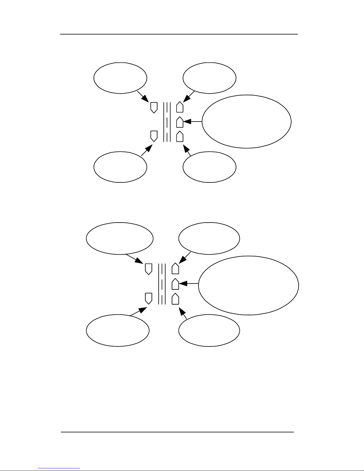
Section 13—Directional Operational Supplement
13.1 STATIONARY ROAD GRAPHIC
Front
Approaching
Rear Receding
Front Receding
Not active in
Stationary modes.
Represents the
officers vehicle.
Rear
Approaching
13.2 MOVING MODE ROAD GRAPHIC
Moving Opposite
Front
Same Direction
Front
On solid (GREEN)
indictes Moving
Mode
Represents the
officers vehicle
Moving Opposite
Rear
Same Direction
Rear
13.2
Page 79

Section 13—Directional Operational Supplement
13.3 TEST MODE
Tuning fork speeds can be
indicated in the Patrol Speed
or Target Speed displays.
LOCK-
REL
TEST AUDIO RANGE STPW
PAT
SET
In Test mode the
Stopwatch indicator
will flash.
TEST MODE
LOCK/E.T.TARGET SPEED
FASTEST
DIRECTIONAL
GOLDEN
KUSTOM SIGNALS, INC.
PATROL SPEED/DIST.
STPW/TEST
EAGLE II
Pressing the TEST button places the radar in test mode,
which is indicated by the flashing STPW/TEST LED. While
in test mode, the radar will display all speeds, both moving
targets and non-moving targets such as tuning forks. The
unit will remain in test mode for 30 seconds. Selecting a
new mode, such as changing from stationary to moving, will
refresh the timeout to 30 seconds allowing fork testing of all
modes.
POWER
NOTE: Pressing the test button while in test mode will turn
off test mode immediately.
13.3
Page 80

Section 13—Directional Operational Supplement
13.4 STATIONARY OPERATION
All instructions are for front antenna operation. Rear
antenna operation is similar and the road graphics will
change accordingly.
13.4.1 STATIONARY ALL
Both Indicators are on solid until a
strongest vehicle is detected.
Then the appropriate indicator is
on solid to indicate: Approaching
or Receding Target
LOCK
REL
TEST AUDIO RANGE STPW
PAT
SET
LOCK/E.T.TARGET SPEED
Both indicators on solid if fastest is
active (searching) Flashes the
appropriate indicator when fastest
vehicle speed found to indicate:
Approaching or Receding Target
STATIONARY ALL
FASTEST
GOLDEN
PATROL SPEED/DIST.
STPW/TEST
DIRECTIONAL
EAGLE II
KUSTOM
SIGNALS, INC.
POWER
To monitor traffic in both directions (the Directional Golden
Eagle II will automatically indicate which direction the
strongest and fastest vehicles are traveling), repeatedly
depress the remote’s MODE switch until “ALL” is
displayed in the PATROL window.
When the radar is operated in the Stationary “ALL” mode,
the TARGET roadway map will automatically light the
appropriate direction LED, indicating the displayed
vehicle’s direction of travel. Both approaching and receding
indicators will be on solid until a vehicle is detected. After a
vehicle is detected, the appropriate direction indicator
(approaching or receding) will be on solid.
13.4
Page 81

Section 13—Directional Operational Supplement
If the “Fastest” function is activated, both the approaching
and receding “fastest” indicators will be on solid until a
faster vehicle is detected, which is faster than the strongest
vehicle speed. After detection, the appropriate fastest
indicator will flash to indicate the direction of the fastest
vehicle: approaching or receding.
13.4.2 STATIONARY APPROACHING ONLY
On solid if fastest is active
(searching) Flashes when fastest
vehicle speed found
STATIONARY APPROACHING
LOCK-
REL
LOCK/E.T.TARGET SPEED
TEST AUDIO
PAT
SET
RANG
FASTEST
E
STPW
STPW/TEST
DIRECTIONAL
GOLDEN
EAGLE II
KUSTOM
PATROL SPEED/DIST.
SIGNALS, INC.
To activate the stationary, approaching targets only mode,
repeatedly depress the MODE switch on the handheld
remote control until “APr” appears in the PATROL display.
When the radar is operated in the Stationary Approaching
mode (“APr”) the TARGET SPEED display will indicate
the strongest approaching target speed. The road indicator
for approaching vehicles will be on solid.
If the “Fastest” function is activated, the approaching fastest
indicator will be on solid until a faster approaching vehicle
is detected. Then the approaching fastest indicator will
flash and the fastest speed will be displayed in the
LOCK/E.T. display.
POWER
13.5
Page 82

Section 13—Directional Operational Supplement
13.4.3 STATIONARY RECEDING ONLY
On solid if fastest is active
(searching) Flashes when fastest
vehicle speed found
STATIONARY RECEDING
LOCK
REL
LOCK/E.T.TARGET SPEED
TEST AUDIO
PAT
SET
RANG
FASTEST
E
STPW
PATROL SPEED/DIST.
STPW/TEST
DIRECTIONAL
GOLDEN
EAGLE II
KUSTOM
SIGNALS, INC.
To place the unit in the stationary mode, monitoring
receding traffic, repeatedly depress the remote control’s
MODE switch until “rEc” is displayed in the PATROL
window.
When the radar is operated in the Stationary Receding
mode, “rEc”, the TARGET SPEED display will indicate the
strongest receding target speed. The road indicator for
receding vehicles will be on solid.
If the “Fastest” function is activated, the receding fastest
indicator will be on solid until a faster receding vehicle is
detected. Then the receding fastest indicator will flash and
the fastest speed will be displayed in the LOCK/E.T.
display.
POWER
13.6
Page 83

Section 13—Directional Operational Supplement
13.5 MOVING MODE OPERATION
Patrol Speed:
In all moving mode operations the PATROL SPEED/DIST.
display indicates the speed of the patrol vehicle and the
green patrol road graphic indicator will be lit.
13.5.1 SAME-DIRECTION
On solid if fastest is active
(searching) Flashes when fastest
vehicle speed found
SAME DIRECTION
LOCK/E.T.TARGET SPEED
FASTEST
PATROL SPEED/DIST.
LOCK
REL
TEST AUDIO
PAT
SET
RANG
E
STPW POWER
STPW/TEST
DIRECTIONAL
GOLDEN
EAGLE II
KUSTOM
SIGNALS, INC.
When operating the radar in Same-Direction mode, the same
direction road indicator corresponding to the antenna
selected will be on solid and the strongest vehicle speed will
be displayed in the TARGET SPEED display.
NOTE: The Directional Golden EAGLE II does not
require any input from the operator in SameDirection mode. The unit will automatically
detect if the target vehicle is slower than the
patrol vehicle and subtract the separation speed
to always provide the operator the correct
speed.
13.7
Page 84

Section 13—Directional Operational Supplement
Same-Direction “FASTEST”
If the Fastest feature is activated, the same direction fastest
road LED indicator will be on solid until a fastest, same
direction vehicle is detected, which is also faster than the
PATROL vehicle’s speed. After detection, the same
direction fastest indicator will flash and the fastest vehicle
speed will be displayed in the LOCK/E.T. window.
NOTE: In the Same-Direction Fastest Mode, the “fastest”
target vehicle must be faster than the patrol vehicle
by 3 MPH. EXAMPLE: Patrol vehicle = 65 MPH.
Large target (strongest) = 43 MPH. Fastest vehicle
= 56. In this event, no fastest speed would be
displayed since the faster vehicle is SLOWER than
the patrol vehicle.
EXAMPLE 2: Patrol vehicle = 65. Large target = 43 MPH.
Fastest vehicle = 78 MPH. The PATROL window will
display 65, the TARGET window will display 43 and the
LOCK/E.T. window will display 78.
13.8
Page 85

Section 13—Directional Operational Supplement
13.5.2 MOVING OPPOSITE
On solid if fastest is active
(searching) Flashes when fastest
vehicle speed found
MOVING OPPOSITE
LOCK/E.T.TARGET SPEED
FASTEST
PATROL SPEED/DIST.
LOCK-
REL
TEST AUDIO
PATSET
RANG
E
STPW
STPW/TEST
DIRECTIONAL
GOLDEN
EAGLE II
KUSTOM
SIGNALS, INC.
POWER
When operating the radar in Moving Opposite mode, the
patrol vehicle and moving opposite road indicator will be on
solid and the strongest vehicle speed will be presented in the
TARGET SPEED display.
If the Fastest feature is activated, the moving opposite
fastest indicator will be on solid until a faster vehicle is
detected, which is faster than the strongest vehicle speed.
After detection, the moving opposite fastest road indicator
will flash and the fastest vehicle speed will be presented in
the LOCK/E.T. display.
If the operator locks a fastest vehicle the fastest indicator
will continue to flash and the TARGET SPEED window
will track the fastest vehicle speed to provide a trackthrough-lock function.
13.9
Page 86

Section 13—Directional Operational Supplement
13.6 FASTEST LOCKING
Fastest speed display
Fastest tracking moves to
TARGET SPEED display
FASTEST LOCK STATIONARY FRONT APPROACHING
and fastest graphic flash
together
PATROL SPEED/DIST.
STPW/TEST
SIGNALS, INC.
LOCK-
REL
LOCK/E.T.TARGET SPEED
TEST AUDIO
PAT
SET
RANG
E
FASTEST
STPW
DIRECTIONAL
GOLDEN
EAGLE II
KUSTOM
If the Lock button is pressed while tracking a fastest vehicle,
the fastest speed will be locked in the LOCK/E.T. display
and the fastest tracking will move to the TARGET SPEED
window. After lock, both LOCK/E.T. display and fastest
indicator will flash together.
Under most operations the mode will not be changed when
switching antennas. However, if the antenna is switched
after locking an approaching fastest vehicle the unit will
automatically switch to receding fastest tracking. This
allows the officer to continue tracking a fastest vehicle as it
passes by. The road graphic indicator for the previous
antenna direction will flash to indicate the direction and
antenna (front or rear) used at the time of lock. If the
antenna is switched back to the original antenna, the antenna
direction indicators will be solid.
POWER
13.10
Page 87

Section 14—Options
14. OPTIONS
14.0 OPTIONS SETUP
The Directional Golden EAGLE II allows the operator to
change certain operating parameters of the unit. The
following is a list of the available parameters. Each has a
number after the option. An example will be given to
instruct the operator how to change the unit.
Option Add
No AUTO UNLOCK 0
Automatic UNLOCK 1
OPEN
Minimum Audio (level 0) 0
Minimum Audio (level 1) 4
Patrol Speed Blank 0
No Patrol Speed Blank 8
Fastest - Push and Hold 0
Fastest - Toggle 16
KSI Video Output 0
Gateway Output 32
DRU Style Output 64
Direct Video Output 96
MPH 0
km/h 128
14.1
Page 88

Section 14—Options
14.1 OPTIONS DESCRIPTIONS
The following is a description of the function of each one of
the Options the operator can set.
14.1.1 AUTOMATIC UNLOCKING OF LOCKED
SPEEDS
The Directional Golden Eagle II defaults to not
automatically unlocking speeds the officer has locked. If
automatically unlocking is required, add 1 to the Options
total. *Due to state regulations, this option cannot be turned
off in some units.
14.1.2 MINIMUM AUDIO LEVEL
The Directional Golden Eagle II defaults to allow the audio
level to be to 0 (audio off). If it is required that the audio
cannot be turned off, add 4 to the Options total. *Due to
state regulations, this option cannot be turned off in some
units.
14.1.3 PATROL BLANK
The Directional Golden Eagle II defaults to allow the
operator to blank the locked patrol speed. If it is required
that the locked patrol speed cannot be blanked, add 8 to the
Options total. *Due to state regulations, this option cannot
be turned off in some units.
14.2
Page 89

Section 14—Options
14.1.4 FASTEST OPERATION
The Directional Golden Eagle II offers two modes of fastest
operation. The default mode is push and hold; in this mode
fastest is active for as long as the operator holds down the
FAST switch and for 2 seconds after it is released. The
alternate mode is toggle; in this mode fastest is alternately
turned on or off by pressing the FAST switch. If fastest
toggle mode is desired, add 16 to the Options total.
14.1.5 INTERFACE OUTPUT PROTOCOL
The Directional Golden Eagle II defaults to allow the radar
unit to interface the KSI Eyewitness® video or giant display
equipment. Contact Kustom's Customer Service
Department at (800)-835-0156 or (620) 431-2700 before
changing the output protocol option.
14.1.6 SPEED READING UNITS
The Directional Golden Eagle II defaults to displaying the
speed-readings in miles per hour. If kilometers per hour
reading are required, add 128 to the Options total.
14.3
Page 90

Section 14—Options
14.2 OPTIONS EXAMPLES
Using the above options list, add all the numbers for the
options you want active. NOTE: default options, such as
MPH and Patrol Blank, have a value of zero (0).
To enter the Options Menu mode, power the unit off, then
press and hold the POWER switch until the power-on
sequence stops. Press the TEST switch until OPt appears in
the TARGET window and a number appears in the
LOCK/E.T. window. This number may be zero.
Using the UP and DOWN arrows (AUDIO and RANGE
switches), increase or decrease the number for the value
needed. If you wish to make these changes permanent (until
changed again), depress the LOCK/REL switch once.
When the options have been accepted, the unit will
automatically return to radar mode.
EXAMPLE: The operator wishes to permanently change
the operation of the unit to the following: Automatic
Unlock = 1, no Patrol Blank = 8, toggle Fastest function =
16, Gateway (unencrypted) output = 32 and MPH = 0.
These numbers are added for a total of 57. When the menu
function is entered (see above), use the UP and DOWN
arrows to adjust the number shown in the LOCK/E.T.
window until 57 is shown. The operator would then depress
the LOCK/REL switch one time and the changes would be
accepted and used every time the radar is powered up.
14.4
Page 91

Section 15—Warranty
15.0 WARRANTY
The Kustom Signals Traffic Safety Radar system is guaranteed
to be free of defects in materials and workmanship for a period
of two (2) years from date of delivery to the Owner or Lessee.
• This Warranty applies only to the original registered Owner
or Lessee on file at Kustom Signals, Inc., and cannot be
assigned or transferred to a third party.
• The Owner or Lessee shall use the Equipment in accordance
with the manufacturer’s operational instructions.
• The Owner’s or Lessee’s exclusive remedy under this
Warranty is limited to repair to the manufacturer’s
operational specifications or replacement, at the sole
discretion of Kustom Signals, Inc. or its agent, of the
Equipment as (i) is covered by this Warranty; (ii) is
delivered to Kustom Signals, Inc. or its agent at the Owner’s
or Lessee’s expense within the term of this Warranty; and
(iii) upon examination thereof discloses to the exclusive
satisfaction of Kustom Signals, Inc. or its agent to have been
defective in material or workmanship. Warranty service and
repairs must be performed by an Authorized Kustom
Signals Warranty Service Center or the Factory Customer
Service Center or this Warranty is void.
• Failure of the Owner or Lessee to observe any conditions set
forth in this warranty; or equipment damage arising from
flood, fire, vehicle collision, act of God or similar event or
catastrophe; or tampering, abuse, or misuse of the
equipment by Owner, Lessee or third party will render the
Owner or Lessee responsible for the cost of bringing the
system within the manufacturer’s operational specifications.
15.1
Page 92

Section 15—Warranty
• This warranty is not intended to supplant normal care and
service by the Owner or Lessee, as specified in the
Operator’s Manual, and shall not apply to Equipment which
has been defaced or damaged through normal usage.
• The liability of Kustom Signals, Inc., if any, with respect to
the equipment, shall be limited as provided in this Warranty.
Kustom Signals, Inc. disclaims any obligation or liability for
the loss of use of the Equipment warranted, loss of time,
inconvenience, commercial loss or other direct,
consequential, special or incidental damages. Kustom
Signals, Inc. makes no warranties of any kind other than as
herein expressly provided, expressed or implied, and
specifically disclaims the implied warranties of
merchantability and of fitness for a particular purpose. You
may have additional rights under this Warranty that vary
from state to state.
• No action for breach of this warranty may be commenced
more than one year after the date of alleged breach.
EQUIPMENT SUPPLIED WITH CONSUMABLE
ITEMS
Items such as tires, non-rechargeable batteries, light bulbs,
transmitter carrying pouch, and microphone cables
w/microphone and windscreen are considered consumable
items and as such are not covered by this warranty.
SMART RADAR
SMART system radar units are warranted for two years,
subject to the warranty terms listed above.
15.2
Page 93

Index
Subject Page
Accuracy..............................................................................2.1
Audio Control........................................................3.5, 4.2, 7.3
Case Law..................................................................10.1, 10.2
Connectors...........................................................................4.4
Displays--Function...............................................................4.1
--Size........................................................................2.3
Equipment Supplied.............................................................3.1
Fan Interference.....3.5, 3.6, 7.4, 7.12, 7.16, 8.2, 8.3, 12.7, 12.8
Fastest Vehicle...............................2.5, 4.2, 4.6, 7.7, 7.11, 7.13
FCC Requirements....................................................11.1, 11.2
Frequency............................................................................2.1
Groundspeed........................................................................8.5
Health Issues........................................................................5.3
Installation--Airbag Information...........................................3.3
Auxiliary Power Receptacle......................................3.2
Front Antenna...........................................................3.4
Rear Antenna............................................................3.6
Indicator, LCU.........................................................3.3
Speedometer Pulse Cable..........................................3.7
Interference-Man-Made........................................................8.2
Natural.....................................................................8.1
Law ................................................................See Case Law
Light Dimming....................................................................4.3
Lock/Release--Auto Release........................7.6, 7.8, 7.10, 7.11
Buttons..............................................................4.2, 4.5
Moving Mode.........................................................7.10
Stationary Mode.......................................................7.6
Maintenance.........................................................................9.1
Maintenance Mode.............................................................7.16
Microwave RF Emissions.....................................................5.3
Minimum Patrol Speed...........................................4.2, 7.9, 8.5
Page 94

Index
Subject Page
Modes--Moving--Opposite...................................................7.8
Moving--Same........................................................7.12
Stationary.................................................................7.5
Stopwatch...............................................................7.14
Moving....................................................................See Modes
Power--Receptacle, Auxiliary...............................................3.2
Requirements............................................................2.1
Range Control...............................................................4.2, 7.3
Remote Control....................................................................4.5
Set-Up .................................................................................7.2
Specifications--General........................................................2.1
Operational...............................................................2.2
Speed Ranges................................................................2.3, 2.4
Speedometer Input—Installation..........................................3.7
Operation................................................................7.16
Synchronization........................................................6.9
Stationary.................................................................See Modes
Stopwatch................................................................See Modes
Switches--Display Unit........................................................4.1
Audio.......................................................................4.2
Lock/Release............................................................4.2
Patrol-Set..................................................................4.2
Power On.................................................................4.3
Range.......................................................................4.2
Stopwatch.................................................................4.3
Test..........................................................................4.2
Page 95

Index
Subject Page
Switches--Remote Control...................................................4.5
Fastest......................................................................4.6
Front/Rear................................................................4.6
Hold.........................................................................4.5
Lock/Release............................................................4.5
Mode........................................................................4.6
Same/Opposite.........................................................4.6
Testing.................................................................................6.1
Automatic Self-Test................................................2.2, 6.2
Failure............................................................................6.8
Manual...........................................................................6.2
Power-On.......................................................................6.1
Speedometer..........................................................6.9, 7.16
Tuning Fork--Moving, Opposite.....................................6.5
Moving, Same..........................................................6.7
Stationary.................................................................6.5
Theory of Operation.............................................................5.1
Tracking History...........................................................7.5, 7.9
Training...............................................................................7.2
Troubleshooting.................................................................12.1
Unsquelch Audio..........................................................3.5, 7.3
Page 96

AIRBAG CAUTION
Equipment mounted in 1994 or later series
police vehicles may interfere with the operation
of passenger side airbags. Information is
available directly from the automobile
manufacturers regarding areas for safe mounting
of equipment such as police radar.
Since this information will vary by vehicle make
and model year, Kustom Signals recommends
contacting the vehicle manufacturer and
following their instructions with respect to
mounting of radar units and other equipment.
For additional mounting suggestions, please
contact the Kustom Signals Customer Service
Department.
Kustom Signals cannot accept any liability for
equipment, which has been mounted in conflict
with the vehicle manufacturer's recommendation
for proper airbag deployment.
Page 97

UNIT SERIAL NUMBER
_____________
ON DUTY TEST OFF DUTY TEST
DATE TEST
FORK/
READ
DRIVE/
RADAR
SIGN TEST
FORK/
READ
DRIVE/
RADAR
SIGN COMMENTS
 Loading...