

Page 1

Kustom Signals, Inc.
Digital Eyewitness® HD
In-Car Video System
Installation Manual
Manual Part Number: 006-1219-00 Rev. 0
Page 2

Copyright © 2017, Kustom Signals, Inc.
All Rights Reserved. Printed in U.S.A.
This publication may not be reproduced, stored in a retrieval system, or transmitted in whole or
in part in any form or by any means electronic, mechanical, photocopying, recording, or
otherwise without prior written permission of Kustom Signals, Inc.
Kustom Signals, Inc.
9652 Loiret Boulevard
Lenexa, KS 66219-2406
Sales: 1-800-4-KUSTOM (1-800-458-7866)
Sales Fax: 913-492-1703
Technical Support: 1-800-835-0156 or 1-620-431-2700
Web: www.kustomsignals.com
Page 3

Important/Notable Information
While all of the information in this manual is important, there are some pieces of information
where special attention needs to be paid to avoid equipment damage, or specific information
needs to be emphasized. This information will be handled as follows:
IMPORTANT
Indicates an operating procedure, practice, or condition that, if
not strictly followed, may cause equipment damage.
Note: Indicates additional information or emphasizes a topic related to the subject
being discussed.
Field Service
Kustom Signals, Inc. can provide field service for start-up assistance, training, maintenance,
and replacement/spare parts for new and existing equipment.
Contact a Kustom Signals, Inc. technical support representative by calling 1-800-835-0156 or
1-620-431-2700.
Careful Placement of Components
Care should be taken when considering the placement of components. This is especially
important with components that will be worn by the officer (i.e., the wireless audio transmitter).
WARNING
Placement of items on the duty belt can restrict ready access to
important equipment.
The location of the wireless audio transmitter or any other
device provided with this system that is carried on the officer’s
person should be chosen with great care and consideration.
After a location is chosen, the officer should test access to and
practice drawing primary items, such as service firearms and
secondary defense devices such as aerosol subject restraint,
batons, and electronic control devices, etc. Proper operation of
handheld radios and other signaling devices should also be
tested as should access to handcuffs and other restraining
devices.
Take Appropriate Steps When Drilling Holes
Some installations may require the technician to drill a hole or holes in the vehicle. In these
cases, the technician should verify prior to drilling that drilling through a panel will not result in
damage to any component behind the panel being drilled.
CAUTION
Once the hole has been drilled, when the technician is installing the component, they need to
be sure that the hole is completely sealed. Sealing the hole will prevent fumes from outside of
the vehicle from entering the passenger compartment.
Manual Part Number:
006-1219-00 Rev. 0
The technician should make sure that the mounting location will
not result in other components being damaged during the
installation, such as when drilling the pilot holes.
If holes are drilled, the technician must be sure that the holes are
completely sealed prior to returning the vehicle to the customer.
i Digital Eyewitness® HD
In-Car Video System
Page 4

This Page Intentionally Left Blank
Digital Eyewitness® HD
In-Car Video System
ii Manual Part Number:
006-1219-00 Rev. 0
Page 5

Digital Eyewitness® HD In-Car Video System
Table of Contents
Chapter Page
1 Product Description ..................................................................................... 1-1
General Description ........................................................................................ 1-1
Basic Digital Eyewitness® HD System ........................................................ 1-1
Optional Eyewitness® HD System Components ......................................... 1-2
Checking the Order ........................................................................................ 1-3
Installer Qualifications .................................................................................... 1-4
Order of Installation ........................................................................................ 1-4
Protecting Against RFI (Radio Frequency Interference) ................................. 1-5
Power/Ground Connection Requirements ...................................................... 1-6
Eyewitness® HD System Serial Numbers ....................................................... 1-6
2 Installing the Tablet Monitor Controller (TMC) .......................................... 2-1
General Description ........................................................................................ 2-1
Preparing the Tablet Monitor Controller (TMC) for the Ball and
Socket Mount Installation ........................................................................ 2-1
Tablet Monitor Controller Installation .......................................................... 2-4
TMC Ball and Socket Mount ..................................................................................... 2-4
Headliner Mount ....................................................................................................... 2-6
3 Installing the Cameras and In-Car Microphone (ICM) ............................... 3-1
General Description ........................................................................................ 3-1
Installing an HD Camera with Standard Combination Camera/
Expanse Audio Transmitter Base Mount (Part # 050-0695-04) ............. 3-1
Initial Checks Prior to Installing Camera on Windshield or Headliner
Mounting Tab .......................................................................................... 3-4
Installing an HD Camera with Windshield Mount (Part # 050-0615-00) ........ 3-5
Installing an HD Camera with Optional Headliner Mount
(Part # 050-0615-00) .............................................................................. 3-9
Installing the In-Car Microphone ............................................................... 3-11
Installing the Rear Seat Camera with Integrated In-Car Microphone ....... 3-12
4 Routing and Installing System Cables ....................................................... 4-1
General Description ........................................................................................ 4-1
Basic Cabling Information .............................................................................. 4-1
Side Airbag Precautions ............................................................................. 4-2
Radio Frequency Interference (RFI) Prevention ......................................... 4-2
Routing Cables Through Bulkheads ........................................................... 4-2
Managing Excess Cable ............................................................................. 4-3
Manual Part Number:
006-1219-00 Rev. 0
iii Digital Eyewitness® HD
In-Car Video System
Page 6

Mini-Octopus (Mini-OTP) Cable (Part # 155-3952-00) ................................... 4-4
Accessory Cable (Part # 155-3956-25) .......................................................... 4-5
Installing the Power Cable (Part # 155-3957-25) ............................................ 4-7
Installing the Power Tamer ............................................................................. 4-8
5 Installation of GPS and Wi-Fi Antennas ..................................................... 5-1
General Information ........................................................................................ 5-1
Installing GPS Components (Part # 015-1599-00) ..................................... 5-1
Installing Wireless N File Transfer 5.0 GHz Antenna Components
(Part # 050-0860-00) ............................................................................... 5-2
6 Installation of the Digital Video Recorder (DVR) ....................................... 6-1
General Description ........................................................................................ 6-1
DVR Front Panel ......................................................................................... 6-1
DVR Rear Panel ......................................................................................... 6-2
DVR Heat Management ........................................................................................... 6-3
DVR / System Serial Number Locations ..................................................... 6-4
Preparing the DVR for Mounting ................................................................. 6-4
Mounting the DVR ....................................................................................... 6-4
7 Installation of the Mobile Data Computer (MDC) Option .......................... 7-1
General Description ........................................................................................ 7-1
Minimum System Requirements ................................................................. 7-1
Eyewitness® HD MDC Installation Instructions ........................................... 7-1
8 Field Verification of File Transfer Operability ............................................ 8-1
General Information ........................................................................................ 8-1
Index .......................................................................................................... Index-1
Digital Eyewitness® HD
In-Car Video System
iv Manual Part Number:
006-1219-00 Rev. 0
Page 7

List of Figures
Figure Page
Figure 1-1. Example Top Tray .............................................................................................. 1 - 3
Figure 1-2. Example Middle Tray ......................................................................................... 1-3
Figure 1-3. Example Bottom Tray......................................................................................... 1-3
Figure 1-4. Serial Number Location on the DVR .................................................................. 1-6
Figure 1-5. HD Camera Serial Number Label ...................................................................... 1-7
Figure 1-6. Monitor Serial Number Label ............................................................................. 1-7
Figure 1-7. Rear Seat Camera Serial Number Label............................................................ 1-7
Figure 1-8. Expanse Transmitter Base Serial Number Label ............................................... 1-8
Figure 1-9. Expanse Transmitter Serial Number Label ........................................................ 1-8
Figure 2-1. Tablet Monitor Controller .................................................................................... 2-1
Figure 2-2. Ball Stud Installed in Display Mounting Plate ..................................................... 2-2
Figure 2-3. Tablet Monitor Controller Cable Connection and Cable Routing ........................ 2-3
Figure 2-4. Align the Display Mounting Plate with the Holes in the Display .......................... 2-3
Figure 2-5. Ferrite Clamp Installation on Tablet Monitor Control Cable ................................ 2-4
Figure 2-6. Display Mount Base ........................................................................................... 2-5
Figure 2-7. Dual Ball Mount Receiver ................................................................................... 2-5
Figure 2-8. Overhead Console Removed ............................................................................. 2-6
Figure 2-9. Headliner Cutout ................................................................................................ 2-6
Figure 2-10. Creating the Hole for the Center Nut .................................................................. 2-7
Figure 2-11. Wire Routing Through Headliner ........................................................................ 2-7
Figure 2-12. Preparing the Fastener for the Center Nut ......................................................... 2-8
Figure 2-13. Final Mounting Position ...................................................................................... 2-8
Figure 3-1. Brace (Top View) ............................................................................................... 3-1
Figure 3-2. Antenna Cable Connection at Expanse Transmitter Base ................................. 3-2
Figure 3-3. Expanse Transmitter Antenna ............................................................................ 3-2
Figure 3-4. Route the Camera and Audio Transmitter Base Cables .................................... 3-2
Figure 3-5. Installing the Sun Visor Clip over the Mounting Bracket .................................... 3-3
Figure 3-6. Proper Final Position of Antenna ....................................................................... 3-4
Figure 3-7. Camera Mounting Hardware .............................................................................. 3-4
Figure 3-8. Windshield Mounting Tab ................................................................................... 3-6
Figure 3-9. Proper Orientation of the Windshield Mounting Tab .......................................... 3-6
Figure 3-10. Jam Nuts Properly Installed ............................................................................... 3-7
Figure 3-11. Top of HD Camera ............................................................................................. 3-8
Figure 3-12. HD Camera on Windshield Mount ...................................................................... 3-8
Figure 3-13. Jam Nuts Properly Installed ............................................................................... 3-9
Figure 3-14. Camera Bracket on Top of Camera ................................................................. 3-10
Figure 3-15. Headliner Mounting Tab ................................................................................... 3-10
Figure 3-16. In-Car Microphone Mounting ............................................................................ 3-11
Figure 3-17. Inline Camera Connection ................................................................................ 3-12
Figure 3-18. Inline Camera Connection Secured with Electrical Tape ................................. 3-13
Figure 4-1. Basic Eyewitness® HD Wiring Layout ................................................................ 4-1
Figure 4-2. Power Cable Routed Through Factory Pass-Thru ............................................. 4-3
Figure 4-3. Managing Cables – Creating a Dog Bone .......................................................... 4-3
Figure 4-4. OTP Cable ......................................................................................................... 4-4
Figure 4-5. OTP Cable Connection at the DVR .................................................................... 4-4
Manual Part Number:
006-1219-00 Rev. 0
v Digital Eyewitness® HD
In-Car Video System
Page 8

Figure 4-6. Wire Color and Uses .......................................................................................... 4-5
Figure 4-7. Power Cable Taped to Fish Tape ...................................................................... 4-7
Figure 4-8. Sample Power Tamer Mounting Location (Inner Fender – Crown Vic) .............. 4-8
Figure 4-9. Chassis Ground Connection (Charger Shown) .................................................. 4-9
Figure 5-1. GPS Antenna – Example A-Pillar Mount ........................................................... 5-1
Figure 5-2. Wi-Fi Antenna Mounting Screws ........................................................................ 5-2
Figure 5-3. Completed Antenna Installation ......................................................................... 5-3
Figure 5-4. Wireless Antenna Connections on Rear of DVR ................................................ 5-3
Figure 6-1. Front Panel of the DVR ...................................................................................... 6-1
Figure 6-2. Rear View of DVR .............................................................................................. 6-2
Figure 6-3. DVR Vent Holes ................................................................................................. 6-3
Figure 6-4. DVR Heat Sink ................................................................................................... 6-3
Figure 6-5. Cage Mounted DVR on Back of Rear Cage – SUV Installation ......................... 6-4
Figure 6-6. Floor Mounted Location of DVR......................................................................... 6-5
Figure 6-7. GPS Antenna Connection .................................................................................. 6-5
Figure 6-8. Wireless File Transfer Antenna Connections ..................................................... 6-6
Figure 6-9. Mini-OTP Cable Connections ............................................................................ 6-6
Figure 6-10. Tablet Monitor Controller (TMC) Connection ..................................................... 6-6
Figure 6-11. MDC Control Connection ................................................................................... 6-6
Figure 6-12. Camera Connections ......................................................................................... 6-7
Figure 6-13. Accessory Cable Connection ............................................................................. 6-7
Figure 7-1. Determine Which Port the Ethernet Cable is Connected to ............................... 7-2
Figure 7-2. Local Area Connection Properties ..................................................................... 7-2
Figure 7-3. Internet Protocol Version 4 (TCP/IPv4) Properties ............................................ 7-3
Figure 7-4. PreInitSettings.json File in Text Editor ............................................................... 7-3
Figure 7-5. MDC Controller .................................................................................................. 7-4
Figure 8-1. Wi-Fi Signal Strength Indicator .......................................................................... 8-1
Figure 8-2. Example Starting File Transfer Session Message ............................................. 8-1
Figure 8-3. Example File Transfer Messages ...................................................................... 8-2
Figure 8-4. Example File Transfer Finished Message .......................................................... 8-2
Figure 8-5. Example File Transfer Failed Message ............................................................. 8-2
Digital Eyewitness® HD
In-Car Video System
vi Manual Part Number:
006-1219-00 Rev. 0
Page 9

Product Description
Chapter 1
Product Description
General Description
This installation manual is intended to provide the installation technician with easy to follow
instructions for installing a Digital Eyewitness® HD in-car video system. The manual is divided
into chapters, each of which provides a set of instructions for installing a specific portion of the
system.
This chapter provides the installer with high-level product information for the Eyewitness® HD
in-car video system.
The Eyewitness® HD is available as a base system package, and may be upgraded with many
additional features. A detailed list of the basic Eyewitness® HD package and the additional
features will be covered on the following pages.
IMPORTANT
This manual is laid out in a component-by-component format.
The technician does not have to install components in the same
order that they appear in the manual. For example, the
technician may want to install the Tablet Monitor Controller
(TMC) prior to the DVR, even though the DVR information
appears first in the manual. All components should be installed
and cables routed prior to installing the vehicle trim panels.
Basic Digital Eyewitness® HD System
The base Eyewitness® HD system is comprised of the following components:
Digital Video Recorder (DVR)
64 GB removable hard drive
Forward facing High Definition camera
Either a Tablet Monitor Controller (TMC), or Mobile Data Computer (MDC) interface
MDC Controller (if equipped with MDC)
Standalone In-Car Microphone (ICM)
Wireless audio transmitter (radio)/docking station
DVR mounting kit
Cabling
Camera/wireless audio transmitter (radio) base combination mount
Manual Part Number:
006-1219-00 Rev. 0
1–1 Digital Eyewitness® HD
In-Car Video System
Page 10

Product Description
Optional Eyewitness® HD System Components
The Eyewitness® HD system may be ordered in many configurations that may include any of
the following components:
Internal 64 GB hard drive (in addition to the removable hard drive – required for
background recording)
Dual wireless audio transmitter (radio)/docking station
Mobile Data Computer (MDC) control (in addition to, or instead of, the 7-inch display)
Radar interface
Window mount or visor mount for primary standalone HD camera (forward facing)
Additional rear seat mounted SD camera with integrated in-car microphone (standalone
in-car microphone (ICM) is not included if rear seat mounted SD camera is ordered)
Additional HD camera or cameras (up to three (3) total) with either a windshield mount
or visor mount
GPS
File transfer (both wired and wireless 5.0 GHz antenna kit options are available)
Ignition modification (used to power the system on when the vehicle ignition key is
turned to the run position)
Digital Eyewitness® HD
In-Car Video System
1–2 Manual Part Number:
006-1219-00 Rev. 0
Page 11

Product Description
Checking the Order
Prior to beginning the installation of the system, the technician should check the items received
against the original order and packing slip. If any items are missing, please notify Kustom
Signals, Inc. at 1-800-835-0156 or 1-620-431-2700.
When the box is opened, the installer will find an installation guide that is a useful reference
tool during the installation. Beneath the installation guide the installer will find that the box has
three (3) foam trays that hold the various components:
The top tray contains most of the cables that are needed for the system.
Note: Each cable has a color-coded tag at the DVR end of the cable that matches a
color key on the rear of the DVR. When installing the cables, the cables should
be routed so the labeled end of the cable is at the DVR.
Figure 1-1. Example Top Tray
The middle tray contains the Tablet Monitor Controller (TMC) (if applicable), cameras,
wireless transmitter, the associated mounting hardware and the Expanse transmitter
antenna.
Figure 1-2. Example Middle Tray
The bottom tray contains the DVR, GPS antenna (optional), and Wi-Fi antennas
(optional) and the associated mounting hardware for these components.
Manual Part Number:
006-1219-00 Rev. 0
Figure 1-3. Example Bottom Tray
1–3 Digital Eyewitness® HD
In-Car Video System
Page 12

Product Description
Installer Qualifications
Only persons who have been properly trained and hold the appropriate qualifications should
attempt to install the Digital Eyewitness® HD in-car video system or any of its components.
WARNING
Before installing, adjusting, or servicing any system
components, the technician should make themselves familiar
with the system and the electrical cabling requirements of the
system.
These instructions have been organized to allow quick access to the information needed for
the proper installation of the Digital Eyewitness® HD system. Critical details for each step in
the procedure will be presented with each step, when needed.
The technician is encouraged to read through the detailed instructions at least once – even if
the technician has previous installation experience on the Eyewitness® systems. As Kustom
Signals, Inc. continues to enhance the product, some modifications have been made to some
of the installation procedures that were presented in the past.
Order of Installation
Kustom Signals, Inc. recommends that the installer follow the following sequence when
installing the Eyewitness® HD system.
IMPORTANT
When selecting the mounting locations for the various
components, the installer should be aware of how long the
cables are for each of the components and how those cables will
be routed. This will prevent having to relocate any components
later due to the cable not reaching the DVR.
1. Install the Tablet Monitor Controller (TMC) (if applicable).
2. Install the forward-facing HD camera/Expanse audio transmitter.
3. Install the standalone in-car microphone or optional rear seat SD camera/in-car
microphone.
4. Install the optional 2nd HD camera (if applicable).
5. Route the Accessory and Power cables.
6. Install the GPS antenna (if applicable).
7. Install the Wi-Fi antenna(s) (if applicable).
8. Route the remaining component cables to the DVR.
9. Install the DVR.
10. Perform the MDC configuration (if applicable).
IMPORTANT
This manual is laid out in a component-by-component format.
Kustom Signals, Inc., recommends that installers follow the
general order, although the order of individual components may
be altered slightly. All components should be installed and
cables routed, prior to installing the vehicle trim panels.
Prior to starting the installation, there are some steps that should be taken by the installer to
prepare for the installation.
Digital Eyewitness® HD
In-Car Video System
1–4 Manual Part Number:
006-1219-00 Rev. 0
Page 13

Product Description
y
1. If the system was ordered with a mounting tab that glues to the windshield, the glue that
secures the mounting tab to the windshield must have at least two (2) hours to dry before
the camera is attached. This mounting tab must be installed at the beginning of the
installation to allow adequate time for the glue to cure. Failure to allow adequate drying
time may result in the bond failing at a later date. This would result in the camera falling
from the windshield, which could result in the camera detaching from the windshield and
creating officer safety issues.
2. If ball and socket mount is being used to mount the TMC, install the ball part of the mount,
using Loctite® Thread Locker Blue 242® on the threads of the ball prior to installing into
the bracket. This must be installed at the beginning of the installation to allow adequate
time for the Loctite® to setup. The Loctite® will setup in 10 minutes and fully cure in 24
hours. Failure to allow adequate drying time may result in the bond failing at a later date.
This could result in the ball coming loose from the TMC, which could result in difficulty
positioning the TMC.
3. Determine the mounting position of the DVR. This should be done prior to routing any
cables, to prevent having to re-route cables.
IMPORTANT
The fuse MUST NOT be installed in the fuse holder in the main
power connector until all other components and cables are
installed and connected. Failure to follow this recommendation
ma
result in damage to the system.
Protecting Against RFI (Radio Frequency Interference)
When installing the system, the following guidelines should be followed to help eliminate
interference that may affect the video signal, audio signal, or both:
1. All of the components of the Eyewitness® HD system should be mounted as far away
from the 2-way radio (and its amplifier) as possible.
2. All cables should be routed as far away from the 2-way radio cables as possible.
3. The antenna for the Expanse transmitter should be mounted as far away as possible from
the antenna for the 2-way radio.
4. The power cable’s ground connection should be connected directly to chassis ground, as
close to the negative post of the battery as possible.
5. The ferrite clamp should be installed on the controller cable near the controller.
6. The DVR chassis should be grounded properly to the vehicle chassis using the supplied
ground cable. It will be attached to the DVR chassis from the factory.
Note: To help ensure that radio interference is eliminated or minimized, it may be
helpful to consult with an experienced radio technician.
Manual Part Number:
006-1219-00 Rev. 0
1–5 Digital Eyewitness® HD
In-Car Video System
Page 14
Product Description
Power/Ground Connection Requirements
The following steps MUST be followed to ensure proper operation of the Digital Eyewitness®
HD in-car video system.
1. A power tamer is included with the system and must be installed for the system to operate
properly . DO NOT substitute other models or manufacturers of similar devices. DO NOT
connect other equipment to the power tamer that is supplied with the Eyewitness® HD
system.
2. Main system power should be connected at the positive power lug at the main power
distribution block. If the main power distribution block does not have a positive power lug
available, the power lead may be connected to the positive post of the battery as a last
resort. On Ford Interceptor vehicles, a factory jumper harness is provided for these
connections.
3. Main system ground should be connected to chassis ground, as close to the negative
post of the battery as possible. On Ford Interceptor vehicles, a factory jumper harness is
provided for these connections.
IMPORTANT
Kustom Signals, Inc. strongly recommends against connecting
the ground lead directly to the negative post of the battery.
Kustom Signals, Inc. strongly recommends against cutting any
of the vehicle wiring.
Eyewitness® HD System Serial Numbers
Whenever service or technical assistance is required, contact a Kustom Signals’ customer
service representative by calling 1-800-835-0156 or 1-620-431-2700. The caller should be
prepared to provide the Serial Numbers for the system components requiring service.
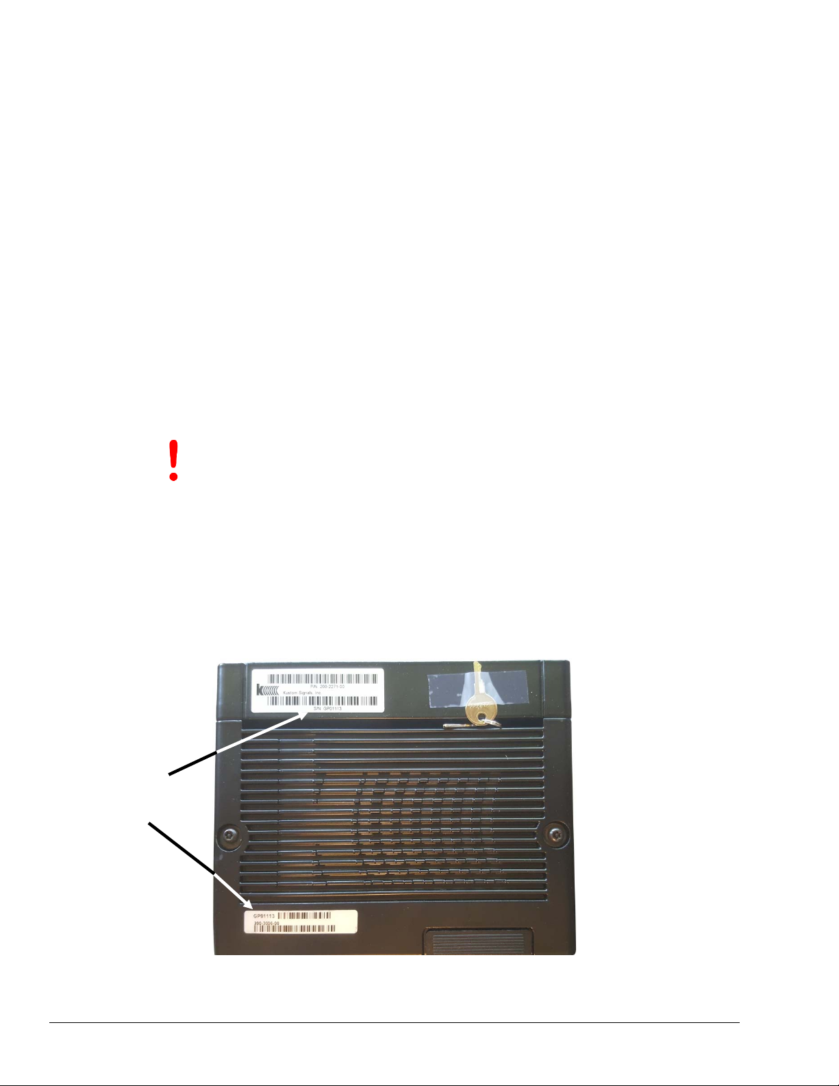
The DVR serial number label is located on the rear panel of the DVR.
Model and
Serial Number
Location
Figure 1-4. Serial Number Location on the DVR
Digital Eyewitness® HD
In-Car Video System
1–6 Manual Part Number:
006-1219-00 Rev. 0
Page 15

Product Description
The serial number label for the HD cameras will be located on the top of the camera housing.
Figure 1-5. HD Camera Serial Number Label
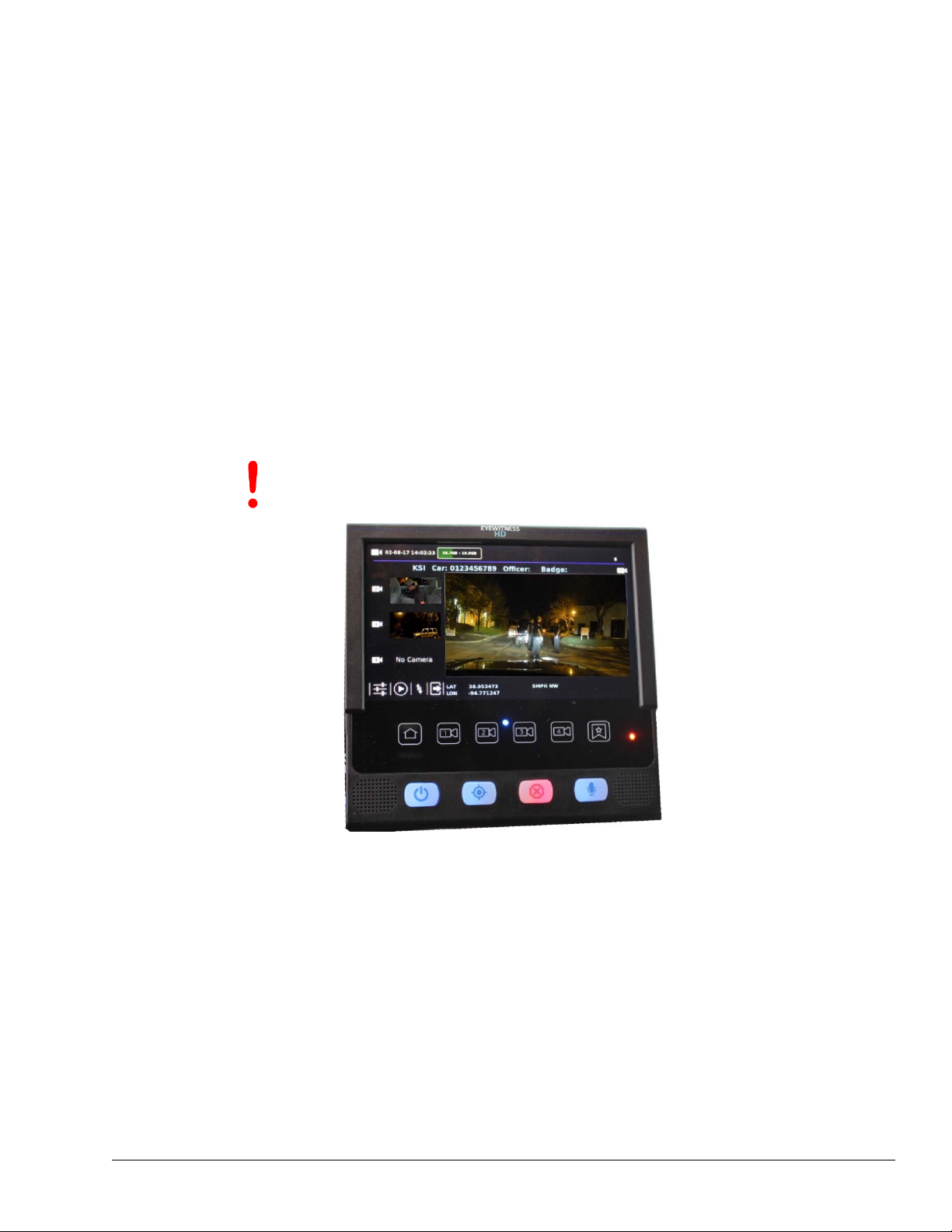
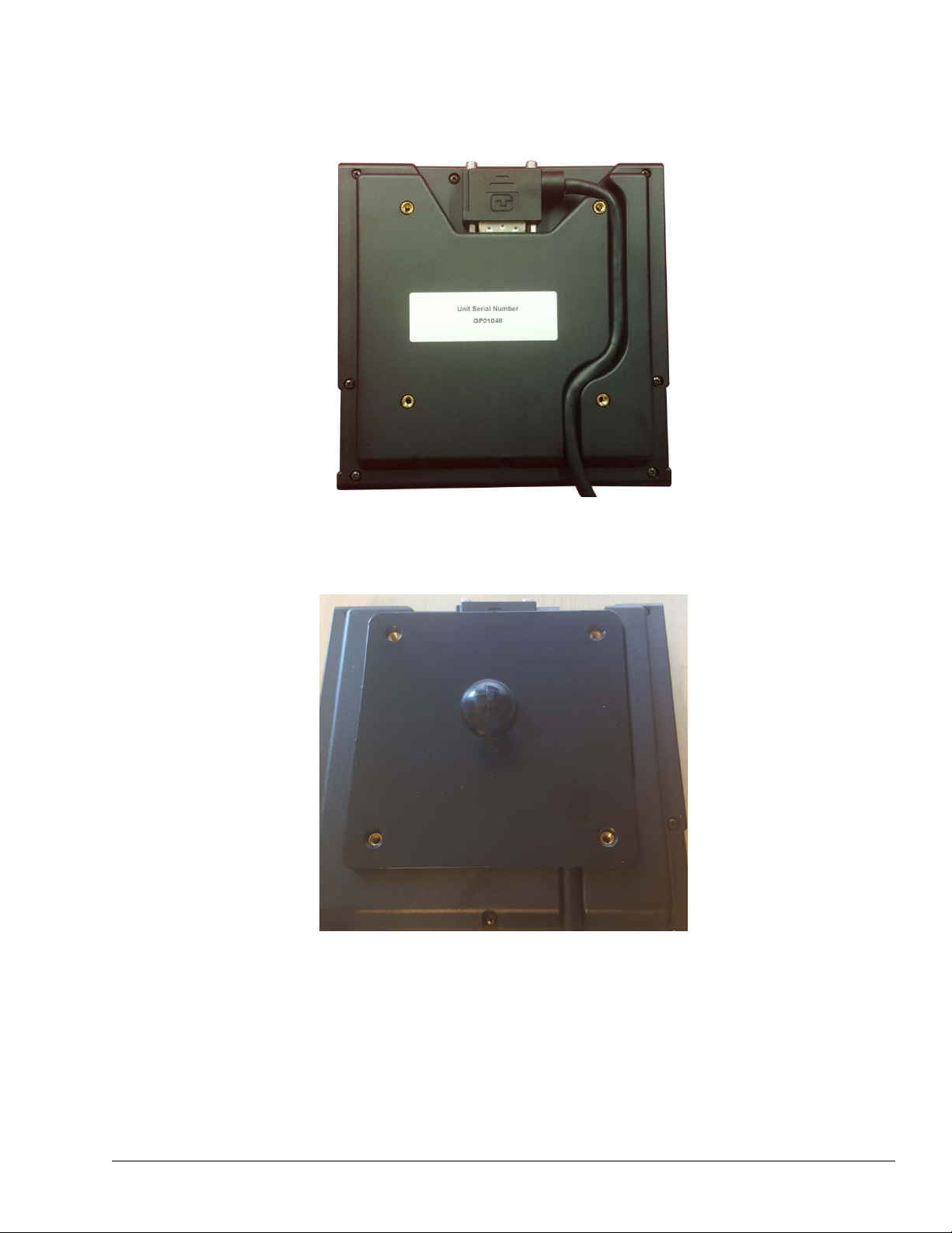
The serial number for the system monitor is located on the back of the monitor.
Figure 1-6. Monitor Serial Number Label
The serial number for the rear seat camera/ICM is located on the bottom surface of the
camera.
Figure 1-7. Rear Seat Camera Serial Number Label
Manual Part Number:
006-1219-00 Rev. 0
1–7 Digital Eyewitness® HD
In-Car Video System
Page 16
Product Description
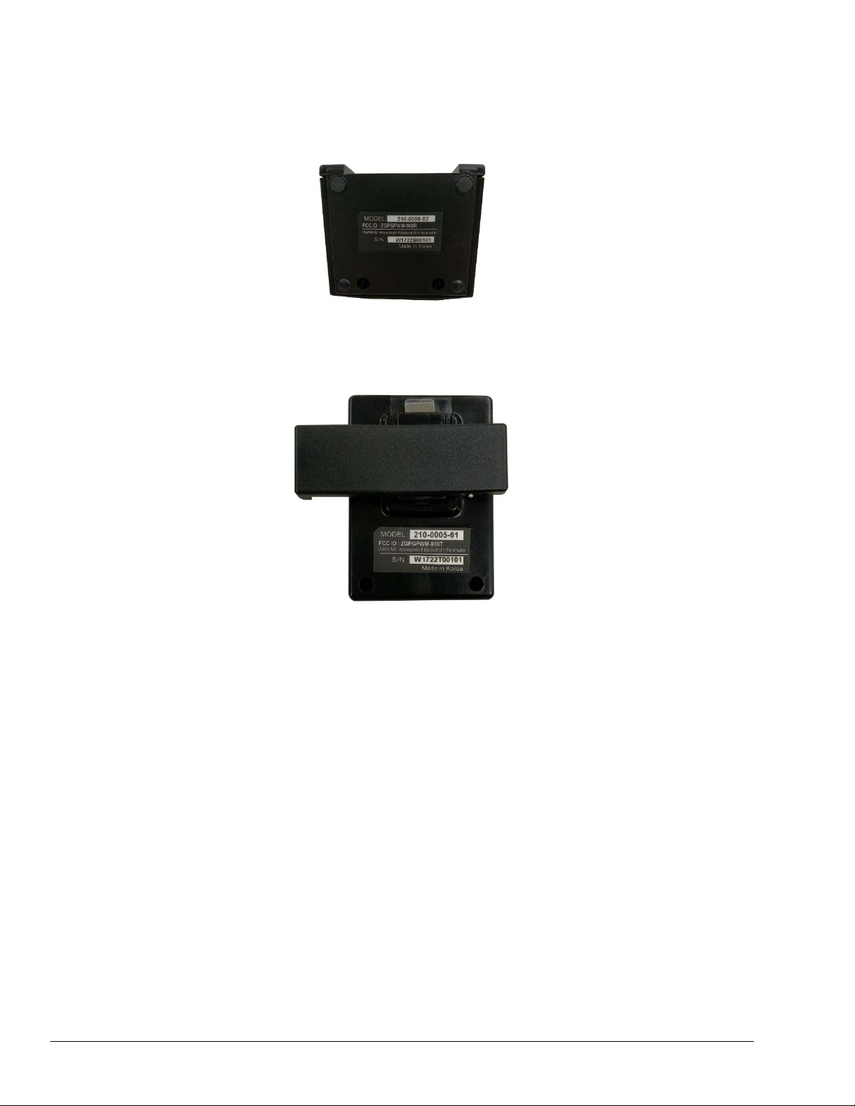
The serial number for the Expanse wireless audio base can be found on the bottom of the
base. Keep in mind that the base is typically installed face down, meaning that the bottom of
the base is actually facing the windshield of the vehicle.
Figure 1-8. Expanse Transmitter Base Serial Number Label
The serial number for the Expanse wireless audio transmitter is found on the back of the
device.
Figure 1-9. Expanse Transmitter Serial Number Label
Digital Eyewitness® HD
In-Car Video System
1–8 Manual Part Number:
006-1219-00 Rev. 0
Page 17
Installing the Tablet Monitor Controller (TMC)
Chapter 2
Installing the Tablet Monitor Controller (TMC)
General Description
The Digital Eyewitness® HD in-car video system provides two monitor options:
Tablet Monitor Controller (Part # 200-2273-00)
Ferrite Clamp (Part # 013-0020-00)
MDC Controller (Part # 200-3054-00)
MDC Controller Cable (Part # 155-4002-22)
Preparing the Tablet Monitor Controller (TMC) for the Ball and Socket Mount Installation
The installer has some flexibility when installing the Eyewitness® HD system controller,
depending on the type of vehicle and the equipment in the vehicle.
IMPORTANT
Do not remove the protective film from the display until it is time
to hand the vehicle back to the customer. This will help protect
the display during installation.
Figure 2-1. Tablet Monitor Controller
The following items are needed to facilitate the installation:
Tablet Monitor Controller (TMC)
Mounting hardware
Cable
Loctite® Thread Locker Blue 242®
Phillips head screwdriver
Pliers
22mm wrench
Manual Part Number:
006-1219-00 Rev. 0
2–1 Digital Eyewitness® HD
In-Car Video System
Page 18
Installing the Tablet Monitor Controller (TMC)
To install the TMC use the following steps:
1. Locate the TMC and place it face down on a soft surface, such as a lint-free towel.
2. Locate the TMC mounting hardware and set them aside.
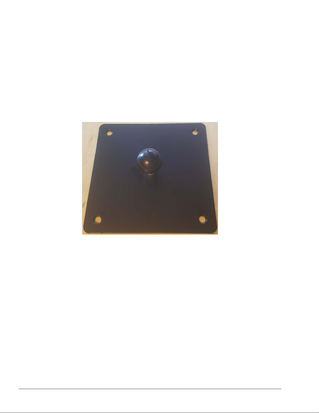
3. Grab the ball stud that will be installed on the TMC mounting bracket. Apply Loctite®
Thread Locker Blue 242® to the threads.
4. Install and tighten the ball stud in the center mounting hole on the back side of the TMC
mounting plate, using a pair of pliers. Set the mounting plate aside. The Loctite® will
setup in 10 minutes and fully cure in 24 hours.
Figure 2-2. Ball Stud Installed in Display Mounting Plate
5. Identify and acquire the cable for the TMC. The cable is color coded on the DVR end.
6. Connect the TMC end of the Tablet Monitor Controller cable to the TMC and secure the
cable with the captive retaining screws.
Digital Eyewitness® HD
In-Car Video System
2–2 Manual Part Number:
006-1219-00 Rev. 0
Page 19
Installing the Tablet Monitor Controller (TMC)
7. Once the TMC cable is secured to the TMC connector, route the TMC cable in the
molded channel on the back of the display.
Figure 2-3. Tablet Monitor Controller Cable Connection and Cable Routing
8. Grasp the TMC mounting plate by the plate, not the ball stud, and position it on the back
of the TMC so that the four (4) screw holes are visible.
Figure 2-4. Align the Display Mounting Plate with the Holes in the Display
9. Acquire the four (4) screws for the TMC mounting bracket. Hand start the screws in the
four (4) holes. Once all four (4) screws have been hand started, use a Phillips head
screw driver to tighten the screws.
Manual Part Number:
006-1219-00 Rev. 0
2–3 Digital Eyewitness® HD
In-Car Video System
Page 20
Installing the Tablet Monitor Controller (TMC)
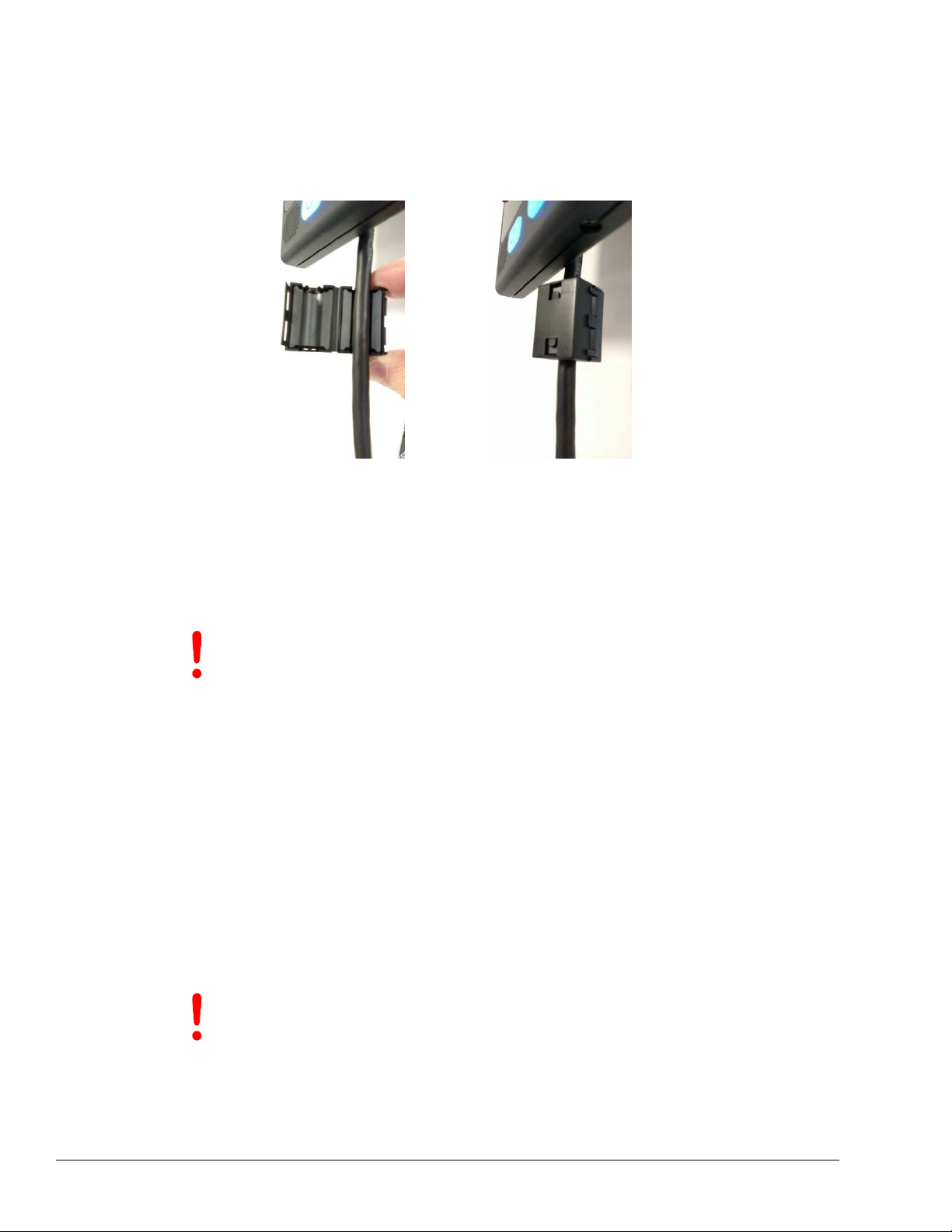
10. Locate the ferrite clamp for the TMC. Open the ferrite clamp and align it with the TMC
cable, just slightly below the bottom edge of the TMC.
11. Make sure that the TMC cable is resting in the slot then close and lock the ferrite clamp.
Figure 2-5. Ferrite Clamp Installation on Tablet Monitor Control Cable
12. Set the TMC assembly aside.
Tablet Monitor Controller Installation
The installer has some flexibility when installing the Eyewitness® HD system controller,
depending on the type of vehicle and the equipment in the vehicle.
IMPORTANT
Use the following criteria when determining where to install the display.
Airbag inflation zone
Officer safety
Line of sight
Critical vehicle controls
TMC Ball and Socket Mount
1. Once the mounting position for the mount has been established, position the mount
base and mark the positions for the three (3) mounting screws.
2. If possible, remove the panel that the mount will be attached to. This is done to prevent
damage to any wiring or other components behind the panel.
IMPORTANT
3. Install the mount base to the panel using the supplied self-tapping screws.
Do not remove the protective film from the display until it is time
to hand the vehicle back to the customer. This will help protect
the display during installation.
If it is not possible to remove the panel to drill the holes, prior to
drilling, make sure that any wiring or components that reside
behind the panel being drilled will not be damaged when drilling
the holes.
4. If the panel that the mount is being installed on was removed from the vehicle, reinstall
it at this time.
Digital Eyewitness® HD
In-Car Video System
2–4 Manual Part Number:
006-1219-00 Rev. 0
Page 21
Installing the Tablet Monitor Controller (TMC)
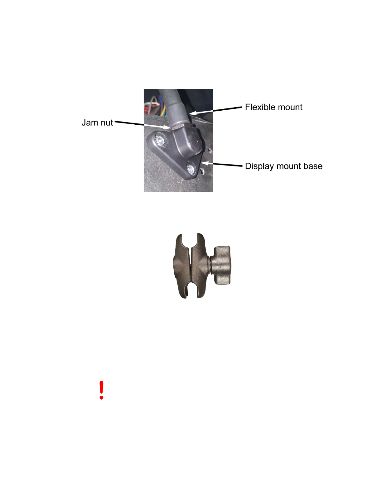
5. Apply Loctite® Thread Locker Blue 242® to the threads of the flexible mount and then
thread the flexible mount into the desired threaded hole on the mount base. The
Loctite® will setup in 10 minutes and fully cure in 24 hours.
6. Tighten the 22mm jam nut against the mount base.
Figure 2-6. Display Mount Base
7. Loosen the knob on the dual ball mount receiver and insert the ball on the flexible
mount into one end of the receiver.
Figure 2-7. Dual Ball Mount Receiver
8. While holding the dual ball mount receiver in place with one hand, lift the display with
the other and insert the ball on the back of the display into the open end of the dual ball
mount receiver.
9. Tighten the knob on the dual ball mount receiver until it is just snug.
10. Adjust the display into the approximate viewing position and tighten the knob fully.
IMPORTANT
When adjusting the TMC, DO NOT grab the TMC to adjust the
position. Instead, grasp the flexible mount to adjust the
position, and then make final adjustments by loosening the dual
ball mount receiver to make the adjustment and then tighten the
dual ball mount receiver to secure it.
Manual Part Number:
006-1219-00 Rev. 0
2–5 Digital Eyewitness® HD
In-Car Video System
Page 22

Installing the Tablet Monitor Controller (TMC)
Headliner Mount
1. Remove the passenger side sun visor clip. If this system will be using a combo mount
for the camera and Expanse wireless audio transmitter, do not install it until after
mounting the TMC.
2. Remove the overhead console.
Figure 2-8. Overhead Console Removed
3. Locate the center point of the front edge of the overhead console.
4. Cut the headliner ¼” left and right of the center point for a total of ½” width and ½ depth.
Leave the headliner material attached at the back of the cut. Cut out the plastic
substrate from the headliner substrate to allow the cable to pass through.
Figure 2-9. Headliner Cutout
Digital Eyewitness® HD
In-Car Video System
2–6 Manual Part Number:
006-1219-00 Rev. 0
Page 23

Installing the Tablet Monitor Controller (TMC)
5. Position the mounting plate for the TMC and place the center nut 3” above the center
cut that was made in the headliner in the previous step. Once properly position, poke a
1/4” hole for the center nut and the top two (2) holes on bracket.
IMPORTANT
Make sure that once the position for the TMC has been selected
the installer must be sure that the TMC’s position will not block
the user’s view of the rearview mirror.
Figure 2-10. Creating the Hole for the Center Nut
6. Run the TMC cable above headliner from passenger side, on the front side of the visor
clip and through the bracket. Leave 18” of cable length.
TMC cable
Overhead
console cable
Figure 2-11. Wire Routing Through Headliner
7. Attach the cable to the tablet and run the cable through the channel.
8. Align the TMC with the mounting plate and install the bottom two (2) screws to secure
the mounting plate to the tablet. Ensure that the top two (2) holes are centered.
9. Acquire two (2) 8/32” x 5/8” machine screws and place one (1) 1/8” x ¾” fender washer
on each screw. Reach through the hole where the overhead console will be installed
and insert each machine screw through the holes that were punched through the
headliner for the two upper corners of the mounting plate and hand start each screw.
Manual Part Number:
006-1219-00 Rev. 0
2–7 Digital Eyewitness® HD
In-Car Video System
Page 24

Installing the Tablet Monitor Controller (TMC)
10. Place one ¼” x ½” hex cap screw with two ¼” x 1-1/4” fender washers through the hole
punched for the center nut. Place one fender washer on the outside of the headliner.
Figure 2-12. Preparing the Fastener for the Center Nut
11. Attach the center nut with TMC to the ¼” x ½” hex cap screw. Do not fully tighten at this
time. This is done to allow the necessary movement for attaching the top two screws.
12. Attach top two 8/32” x 5/8” screws into top two holes. Do not fully tighten either side until
both screws have been started. Once both are started, proceed to tighten snug. Do not
over tighten.
13. Tighten ¼” x 1/2” hex cap screw snug. Do not overtighten as it could penetrate the
TMC.
14. Place excess cable above headliner and reattach overhead.
15. Attach visor clip. When reattaching clip, ensure that the TMC cable is routed in front of
the clip towards the windshield and it is not pinched.
Digital Eyewitness® HD
In-Car Video System
Figure 2-13. Final Mounting Position
2–8 Manual Part Number:
006-1219-00 Rev. 0
Page 25

Installing the Camera and In-Car Microphone (ICM)
Chapter 3
Installing the Cameras and In-Car Microphone (ICM)
General Description
The information in this chapter applies to the following Kustom Signals, Inc. components:
HD camera (Part # 200-3048-00)
HD camera cable (Part # 155-3951-25)
Combination mount (camera and Expanse audio transmitter base) (Part # 050-0695-04)
Windshield mount (Part # 050-0615-00)
Each of the above mounts is used in conjunction with the HD camera and HD camera cable.
Installing an HD Camera with Standard Combination Camera/Expanse Audio Transmitter Base Mount (Part # 050-0695-04)
In the standard configuration, the primary HD camera on the Eyewitness® HD system will be
delivered preassembled on the standard combination mount, along with the Expanse audio
transmitter base.
The technician will need the following items to install the camera:
Camera/audio transmitter base/combo mount assembly
Supplied screws
Phillips head screwdriver
HD camera cable
1. Loosen the brace and slide it rearward on the bracket so that it is approximately ¼ to
½-inch from the front edge of the bracket and then secure it. This is done to keep it out of
the way until the final position of the combo mount is determined.
Manual Part Number:
006-1219-00 Rev. 0
Figure 3-1. Brace (Top View)
3–1 Digital Eyewitness® HD
In-Car Video System
Page 26

Installing the Camera and In-Car Microphone (ICM)
2. Connect the camera cable to the camera. The end of the cable without the color code
should be connected to the camera.
3. Connect the audio cable to Expanse transmitter base. The end of the cable without the
color code should be connected to the Expanse transmitter base.
Figure 3-2. Antenna Cable Connection at Expanse Transmitter Base
4. Connect the antenna cable to the Expanse transmitter base. The antenna will be found in
the same tray as the base in the shipping box.
Figure 3-3. Expanse Transmitter Antenna
5. Route the three cables forward of the camera pivot assembly, out the left side of the
bracket, and then up and over the top of the combo bracket.
Figure 3-4. Route the Camera and Audio Transmitter Base Cables
Digital Eyewitness® HD
In-Car Video System
3–2 Manual Part Number:
006-1219-00 Rev. 0
Page 27

Installing the Camera and In-Car Microphone (ICM)
6. Pivot the sun visor out of the way.
7. Remove the factory screw(s) that are used to secure the sun visor clip to the headliner.
8. Remove the sun visor clip.
9. Position the bracket in its mounting position.
10. Position the sun visor clip over the mounting bracket. Line up the clip with the large,
square hole in the bracket.
11. Install the new, longer mounting screws from the mounting kit to secure the clip and the
mounting bracket to the headliner.
CAUTION
The kit comes with two (2) sets of
screws of different lengths. When
possible use the shorter pair of screws.
If the longer screws are used, they may
penetrate the outer roof panel.
Figure 3-5. Installing the Sun Visor Clip over the Mounting Bracket
12. Make sure that the spot on the windshield for mounting the audio antenna is clean and
dry.
13. Remove the plastic film that covers the adhesive strip on the back side of the antenna.
14. Position the antenna at the top of the windshield, with the cord routed back up under the
headliner. The recommended location is on the passenger side of the vehicle in the
upper corner of the windshield.
Note: Any excess cable for the remote antenna should be dog-boned and stowed above
the headliner. Refer to Managing Excess Cable in Chapter 4, Cable Installation,
for information on how to dog-bone the cable.
Manual Part Number:
006-1219-00 Rev. 0
3–3 Digital Eyewitness® HD
In-Car Video System
Page 28

Installing the Camera and In-Car Microphone (ICM)
Figure 3-6. Proper Final Position of Antenna
IMPORTANT
When installing in a vehicle with RF sensitive electronic
components, it is important to keep the Expanse (Radio) base
antenna as far away as possible from those components to
eliminate any possible interference with those devices.
15. Route the cables for the camera and wireless audio transmitter to the DVR. If the system
includes a single transmitter, the cable for that transmitter must be connected to the
AUDIO 1 connector on the mini-OTP cable at the DVR. Refer to Mini-Octopus
(Mini-OTP) Cable in Chapter 4, Cable Installation, for more information.
Initial Checks Prior to Installing Camera on Windshield or Headliner Mounting Tab
Prior to beginning the installation of any of the available cameras used on the Digital
Eyewitness® HD system, the technician needs to validate that the following items have been
taken into account:
1. The mounting position of the camera should result in minimal obstruction of the driver’s
field of the view.
2. The mounting position of the camera should result in optimum camera field of view out
the front windshield.
3. The mounting position of the camera should result in no interference with airbag
deployment.
4. The mounting position of the camera should result in no compromise in the safety of any
potential vehicle occupants in the event of a collision.
In general, the ability of the technician to satisfy these requirements will increase by moving
the mounting position of the camera as high as possible on the windshield.
Refer to the following drawing for proper tab positioning before marking the mounting location
on the windshield. The mounting location should be marked on the outside of the windshield.
Digital Eyewitness® HD
In-Car Video System
Figure 3-7. Camera Mounting Hardware
3–4 Manual Part Number:
006-1219-00 Rev. 0
Page 29

Installing the Camera and In-Car Microphone (ICM)
Since most vehicles are equipped with a passenger side airbag, obtain a copy of the airbag
deployment zone from the manufacturer. Glue the mounting tab in a location that places the
camera in a safe zone. Possible locations to consider (subject to the airbag deployment
information) include:
to the left (driver’s side) of the rear-view mirror
at the far-left side of the windshield
Acceptable video performance can be achieved with the camera aimed through the solar/UV
tint at the top of many windshields. If the performance of the camera in this position is
unacceptable, on some vehicles it may be possible to scrape a small area of this tint away with
a razor blade.
Another issue that may affect the location is the possible presence of supervisor light
assemblies. These light assemblies are typically installed inside the vehicle along the top
edge of the windshield.
Installing an HD Camera with Windshield Mount (Part # 050-0615-00)
Prior to beginning the installation procedure, it is critical that the technician has addressed all
of the issues mentioned in the Initial Checks information earlier in this chapter.
The technician will need the following tools:
Mounting kit (Part # 050-0615-00)
#1 Phillips head screwdriver
#2 Phillips head screwdriver
7/16” wrench
HD camera and cable
Rubbing Alcohol
Sandpaper/Scotch-Brite™ pad
Rearview mirror adhesive kit or J-B Weld® ClearWeld™
Clean cloth
1. Locate the mounting tab for the camera mount. Inspect the mounting tab. It must be
properly oriented to hold the mount.
Note: The mounting tab is painted black on all surfaces, except for the surface that will
face the windshield.
IMPORTANT
The technician should mark the desired mounting position on
the OUTSIDE of the windshield to assist in positioning the
mounting tab.
Manual Part Number:
006-1219-00 Rev. 0
3–5 Digital Eyewitness® HD
In-Car Video System
Page 30

Installing the Camera and In-Car Microphone (ICM)
y
Figure 3-8. Windshield Mounting Tab
Figure 3-9. Proper Orientation of the Windshield Mounting Tab
2. Use a clean, lint-free cloth that is saturated with rubbing alcohol to clean the mounting
location on the inside of the windshield and the mounting surface of the mounting tab.
3. This step applies when using the Rearview mirror adhesive kit.
a. Locate the activator solution for the adhesive. Squeeze the activator vial until it
breaks. Once the vial breaks, remove the sleeve.
b. Apply a generous amount of activator to the area of the windshield where the
mounting tab will be mounted. Set the mounting tab aside.
IMPORTANT
The activator MUST be allowed to dry for a minimum of five (5)
minutes. Failure to do so will compromise the bonding strength
of the adhesive and will likel
the camera will fall and may be damaged as a result.
result in a failure. If the bond fails,
c. Locate the tube of adhesive and remove the cap. It may be necessary to cut or
snap the cap off.
d. Apply one (1) or two (2) drops of adhesive to the side of the mounting tab that will
be touching the windshield.
e. Carefully position the mounting tab on the windshield, making sure that it is
properly positioned. The side with the adhesive should be placed against the
windshield where the activator was placed earlier in this procedure.
Digital Eyewitness® HD
In-Car Video System
3–6 Manual Part Number:
006-1219-00 Rev. 0
Page 31

Installing the Camera and In-Car Microphone (ICM)
f. Hold the mounting tab in this position for one (1) minute before releasing it. After
one (1) minute, the technician may use painter’s tape to hold the mounting tab in
position while the adhesive continues to set up.
IMPORTANT
The technician needs to make sure to remove all tape adhesive
residue from the windshield after removing the tape.
g. Allow the adhesive to cure for two (2) hours.
IMPORTANT
IMPORTANT
The adhesive MUST be allowed to cure for a minimum of two (2)
hours before installing the camera on the mounting tab. Failure
to do so will compromise the bonding strength of the adhesive
and will likely result in a failure.
If the mounting tab needs to be removed after the adhesive has
cured, use Loctite
Distributors of this product may be located by calling
1-800-323-5206.
®
Corporation’s Chisel Gasket Remover 790.
4. This step applies when using the J-B Weld® ClearWeld™.
a. Remove the replaceable cap.
b. Press down on plunger and squeeze equal amounts onto a disposable surface.
c. Mix the epoxy thoroughly.
d. Apply an even coat of the epoxy to the back of the mounting tab with appropriate
tool.
IMPORTANT
The adhesive MUST be allowed to cure for a minimum of one (1)
hour before installing the camera on the mounting tab. Failure to
do so will compromise the bonding strength of the adhesive and
will likely result in a failure.
If the temperature is below 40ºF, the epoxy will require more
time to set.
5. Locate the camera pivot assembly and the jam nuts for the pivot assembly mounting
studs.
6. Install the two (2) jam nuts on the pivot assembly mounting studs. One nut goes on each
stud. Thread the nuts all the way down the length of the threads.
Figure 3-10. Jam Nuts Properly Installed
Manual Part Number:
006-1219-00 Rev. 0
3–7 Digital Eyewitness® HD
In-Car Video System
Page 32

Installing the Camera and In-Car Microphone (ICM)
7. Locate the parting line on the body of the pivot assembly. This parting line is off-center.
Thread the pivot assembly stud that is on the longest end of the pivot assembly into the
threaded hole on the mounting bracket of the camera. Make sure to thread the stud into
the hole until the jam nut is as close to the bracket as possible.
Figure 3-11. Top of HD Camera
8. Tighten the jam nut against the camera bracket to secure the pivot assembly in place and
prevent it from backing out. Failure to perform this step will result in difficulty maintaining
the camera position during operation.
9. Once the adhesive has cured for a minimum of two (2) hours, thread the opposite end of
the pivot assembly into the mounting bracket that was previously installed on the
mounting tab on the windshield.
10. Tighten the jam nut against the bracket.
11. Connect the cable to the camera and route the cable to the DVR. The cable connection
is keyed. Align the camera cable with the socket by applying light pressure and slowly
rotate the connection until the keyways line up. Once aligned, press the connector into
the camera socket until the camera connector is fully seated.
Digital Eyewitness® HD
In-Car Video System
Figure 3-12. HD Camera on Windshield Mount
3–8 Manual Part Number:
006-1219-00 Rev. 0
Page 33

Installing the Camera and In-Car Microphone (ICM)
Installing an HD Camera with Optional Headliner Mount (Part # 050-0615-00)
Prior to beginning the installation procedure, it is critical that the technician has addressed all
of the issues mentioned in the Initial Checks information earlier in this chapter. The mounting
tab used for this setup is the same tab as used with the windshield mount.
The following items are needed to facilitate the installation:
Mounting kit (Part # 050-0615-00)
Zoom camera and cable
Phillips head screwdriver or screw gun and bit
Use the following steps to install the zoom camera with optional headliner mount:
1. Locate the camera pivot assembly and the jam nuts for the pivot assembly mounting
studs.
2. Install the two (2) jam nuts on the pivot assembly mounting studs. One nut goes on each
stud. Thread the nuts all the way down the length of the threads.
Figure 3-13. Jam Nuts Properly Installed
3. Locate the parting line on the body of the pivot assembly. This parting line is off-center.
Thread the pivot assembly stud that is on the shortest end of the pivot assembly into the
threaded hole on the mounting bracket. Make sure to thread the stud into the hole until
the jam nut is as close to the bracket as possible.
4. Tighten the jam nut against the bracket to secure the pivot assembly in place and prevent
it from backing out. Failure to perform this step will result in difficulty maintaining the
camera position during operation.
Manual Part Number:
006-1219-00 Rev. 0
3–9 Digital Eyewitness® HD
In-Car Video System
Page 34

Installing the Camera and In-Car Microphone (ICM)
5. Thread the camera onto the stud on the opposite end of the pivot assembly.
Figure 3-14. Camera Bracket on Top of Camera
6. Locate the metal lip above the headliner where the bracket will be installed.
Figure 3-15. Headliner Mounting Tab
7. Secure the bracket to the metal lip using the self-tapping screw.
IMPORTANT
Be careful when selecting the screw. The screw needs to be
long enough to adequately secure the bracket, but not so long
that it hits the windshield. If the technician selects a screw that
is too short, the bracket may come loose and fall. If the
technician selects a screw that is too long, the screw will
contact the windshield.
Digital Eyewitness® HD
In-Car Video System
3–10 Manual Part Number:
006-1219-00 Rev. 0
Page 35

Installing the Camera and In-Car Microphone (ICM)
Installing the In-Car Microphone
To install the in-car microphone, the technician will need the following items:
In-car microphone
Mounting screws
Phillips head screwdriver
1. Locate the in-car microphone and the mounting screws.
2. Determine the mounting location. Typically, the in-car microphone will be mounted high
up on the trim panel of the “C” pillar of the vehicle. This is the vertical structure directly
behind the rear-seat door.
Figure 3-16. In-Car Microphone Mounting
3. Position the in-car microphone with the cable exiting out the top.
4. Using a screwdriver, install the two mounting screws.
5. Route the in-car microphone cable to the DVR, hiding the cable along the way behind the
vehicle’s trim panels.
Manual Part Number:
006-1219-00 Rev. 0
3–11 Digital Eyewitness® HD
In-Car Video System
Page 36

Installing the Camera and In-Car Microphone (ICM)
Installing the Rear Seat Camera with Integrated In-Car Microphone
The rear seat camera is intended to be mounted to capture the actions of detainees that are
seated in the rear seat of the vehicle. Kustom Signals, Inc. recommends that the camera be
mounted on the side of the vehicle that is opposite from where detainees are typically seated.
Typically, the camera is mounted at the coat hook in the rear seat area, but there is some
flexibility in where it can be mounted. For example, the camera may also be mounted on the
cage partition between the front and rear seating areas.
To install the camera, the technician will need the following items:
Phillips head screwdriver
Small flat head screwdriver or a pick.
Drill and 1/8” drill bit (only if pilot holes are needed)
1. Determine whether the camera will be mounted on the driver or passenger side of the
vehicle.
2. For a coat hook mounting location:
a. Locate the coat hook where the camera will be mounted.
b. If the coat hook has a protective cover that is covering the screw, remove the
cover using a small flat head screwdriver or a pick.
c. Remove the screw and coat hook.
d. Route the camera pigtail through the hole in the headliner where the coat hook
was installed, and out through the door opening.
e. Position the bracket in the mounting position at the coat hook.
f. Install the mounting screw to secure the bracket to the existing coat hook mount.
3. Connect the inline camera connector to the camera cable.
Digital Eyewitness® HD
In-Car Video System
Figure 3-17. Inline Camera Connection
3–12 Manual Part Number:
006-1219-00 Rev. 0
Page 37

Installing the Camera and In-Car Microphone (ICM)
j
4. Secure the connection using a couple of wraps of electrical tape. Just use enough tape
to secure the connection.
Figure 3-18. Inline Camera Connection Secured with Electrical Tape
5. Align the holes in the camera with the holes in the camera bracket.
IMPORTANT
The camera should be positioned so that the cable attachment at
the camera is on top when the camera is installed.
6. Loosely install the screws that will secure the camera to the bracket.
7. Once both screws have been started, adjust the final position of the camera and tighten
the screws.
8. Route the cable to the DVR.
IMPORTANT
Once the system has been fully installed and powered on, verify
that the camera position has been ad
the desired area of the rear seat.
usted so that it will capture
Manual Part Number:
006-1219-00 Rev. 0
3–13 Digital Eyewitness® HD
In-Car Video System
Page 38

Installing the Camera and In-Car Microphone (ICM)
This Page Intentionally Left Blank
Digital Eyewitness® HD
In-Car Video System
3–14 Manual Part Number:
006-1219-00 Rev. 0
Page 39

Routing and Installing System Cables
Chapter 4
Routing and Installing System Cables
General Description
Cabling of the Eyewitness® HD system is a straightforward process. However, there are
several precautions that the installation technician needs to follow. Prior to installing the
cables, it is important that the technician has an understanding of the cables used and the
basic layout of the system.
Primary Wi-Fi Antenna Connections
Figure 4-1. Basic Eyewitness® HD Wiring Layout
Basic Cabling Information
The design intent for the cables is that they be routed through the right-hand door sill area.
However, if the right-hand door sill area was used for the routing of radio cables, an alternate
route should be used.
The cabling is end specific. The cables are color coded and the end with the color code goes
to the DVR.
Manual Part Number:
006-1219-00 Rev. 0
4–1 Digital Eyewitness® HD
In-Car Video System
Page 40

Routing and Installing System Cables
Side Airbag Precautions
If the vehicle is equipped with side airbags, the type of side airbag used will have an effect on
how the cables will be routed. The technician needs to use care when selecting the route that
they are going to run their cables. If the cable runs across an airbag, the cable could impede
the airbags deployment, or the cable could break and injure the passenger.
Kustom Signals, Inc. highly recommends that, where possible, cables should be routed away
from the airbags. For example, if the vehicle has side curtain airbags, it would be better to
route the cables under the doorsill trim plate.
Radio Frequency Interference (RFI) Prevention
Radio Frequency Interference (RFI) can cause operational problems, such as video or audio
distortion. Typically, RFI can be prevented by careful consideration of how the cables are
routed through the vehicle. The technician should follow these precautions:
DO NOT route the Eyewitness® HD system cables near the cables for the two-way radio
system.
DO NOT bundle the Eyewitness® HD cables with the cables that belong to other
systems.
In the event that RFI is causing distortion of the video or audio in the system, the technician
should check the routing of the cables for the Eyewitness® HD system. Make sure they are not
routed in the same area with the two-way radio system cables. Re-route the cables as
necessary.
Routing Cables Through Bulkheads
The installation technician needs to use care when routing cables through the bulkheads
(formerly referred to as firewalls) of the vehicle. When possible, the factory pass-thru (holes)
should be used. The pass-thru should be fitted with a grommet to prevent the sharp metal
edges of the bulkhead from cutting the sheath of the cable. If the technician is able move the
factory cables back and forth through the factory pass-thru, there should be adequate room to
route the Eyewitness® HD cables through the same pass-thru.
When determining which pass-thru to use, the technician should do a thorough inspection to
make sure that they will not be routing cables near the exhaust, heat shields, or rotating
components. They also need to use care to not damage the sheath on the cable.
It is advisable to use a tool to assist in pulling the cable through the pass-thru. The technician
may choose to use fish tape or an old aerial to help in routing the cable through the pass-thru.
The technician will feed the fish tape through the pass-thru from the side that they want to feed
the cable to. Once the fish tape is through the pass-thru, the technician will tape the end of the
cable securely to the fish tape and pull the cable through.
Digital Eyewitness® HD
In-Car Video System
4–2 Manual Part Number:
006-1219-00 Rev. 0
Page 41

Routing and Installing System Cables
Figure 4-2. Power Cable Routed Through Factory Pass-Thru
Managing Excess Cable
In many installations, the technician will end up with excess cable that needs to be properly
managed to avoid creating operation issues with the Eyewitness® HD or other vehicle systems.
The technician should NEVER coil excess cable. Instead, they should wrap the cable into a
dog bone shape and secure it with cable ties. This will avoid creating unwanted magnetic
fields, which may contribute to RFI.
Figure 4-3. Managing Cables – Creating a Dog Bone
Manual Part Number:
006-1219-00 Rev. 0
4–3 Digital Eyewitness® HD
In-Car Video System
Page 42

Routing and Installing System Cables
Mini-Octopus (Mini-OTP) Cable (Part # 155-3952-00)
The Eyewitness® HD system uses a mini-octopus, or OTP cable. This cable has a single
connector on one end that connects to the DVR, while the opposite end branches out to
connect to several components.
Figure 4-4. OTP Cable
Figure 4-5. OTP Cable Connection at the DVR
The Mini-OTP cable has connections for the following functions:
Audio 1
Audio 2 Input (optional)
Radar Input (optional)
Each connection is color coded for the component that it will attach to. If the system includes a
single Expanse audio transmitter, the cable for that transmitter must be connected to the
AUDIO1 connector on the mini-OTP cable.
Digital Eyewitness® HD
In-Car Video System
4–4 Manual Part Number:
006-1219-00 Rev. 0
Page 43

Routing and Installing System Cables
Accessory Cable (Part # 155-3956-25)
The accessory cable has a male connector on one end and 13 individual wires on the opposite
end. The cable also includes a foil shielding material. Each wire has a specific purpose and is
identified by color.
Wire Color Purpose
Yellow (at DVR) Ignition sense circuit going to optional Back Up Battery (BUB)
Blue Brake input
Red Lightbar input
Orange AC Siren +
Black AC Siren –
Orange/Black DC Siren
White/Red Door ajar sense
Red/White Ignition sense
Green Ground (at this time, this wire is not connected during installation)
Blue/Black Customer configurable trigger
White/Black Customer configurable trigger
Red/Black Customer configurable trigger
White Customer configurable trigger
Figure 4-6. Wire Color and Uses
Each trigger may be configured to activate a specific camera, or record itself (visual indicator
on screen) or have an individual lookback buffer for a specific camera. Each trigger may also
be set up for reverse logic, or set up for a specific range.
Prior to connecting any of these wires, the technician needs to have a discussion with the
customer to determine how they want to trigger the DVR to record.
Many, if not most, departments will want the system to start recording when the emergency
lights turn on. Since the emergency light systems have multiple operating modes, the
customer needs to dictate which modes will initiate recording. Once the determination has
been made, the technician will need to inspect the emergency light system to determine which
circuit they will need to connect to for the signal to the DVR to initiate the recording.
Manual Part Number:
006-1219-00 Rev. 0
4–5 Digital Eyewitness® HD
In-Car Video System
Page 44

Routing and Installing System Cables
Also, most departments will want the system to start recording when the siren is activated.
Once again, the technician will need to inspect the system to determine which circuit they will
need to connect to for the signal to the DVR to initiate the recording.
IMPORTANT
Kustom Signals, Inc. does not recommend or condone cutting
any of the vehicle wiring.
To connect the end of the cable that does not have a connector, the technician should use the
following steps:
1. Strip the outer sheath off the cable, as needed.
2. Pull the foil shielding material back to the length that the sheath was trimmed to and trim
the foil off.
3. Separate the wires inside the cable.
4. Determine which of the wires will be used. Trim any wires that will not be used back to
the same length as the sheath.
5. Depending on how the wires will be connected to their intended circuits, prepare the ends
of the wire. This may mean stripping back the sheath on the end of the wire.
6. Connect the Red wire to the desired circuit for the emergency light interface. The type of
connection here will vary based on who manufactured the emergency lights controller.
7. Connect the Orange wire to the desired circuit for the Siren + interface. The type of
connection here will vary based on who manufactured the siren controller.
8. Connect the Black wire to the desired circuit for the Siren – interface. The type of
connection here will vary based on who manufactured the siren controller.
9. Connect the Blue wire to the brake actuator circuit. Kustom Signals, Inc. strongly
recommends against cutting the wire for the brake actuator circuit. Instead, Kustom
Signals, Inc. provides a “Scotch Lock” type connector to facilitate the connection.
10. If the Ignition Modification option was ordered (Part # 050-0769-00), splice the Red/White
wire to the provided fuse tap pigtail harness that was provided with the system. Remove
the appropriate ignition circuit fuse in the fuse box and install the pigtail fuse connector in
its place. The original ignition circuit fuse should then be installed into the connector end
of the pigtail.
IMPORTANT
When connecting the Eyewitness® HD wiring to the vehicle for
the brake circuit or ignition circuit, the installer will need to
identify the appropriate circuit to tie into using the provided
connectors.
Digital Eyewitness® HD
In-Car Video System
4–6 Manual Part Number:
006-1219-00 Rev. 0
Page 45

Routing and Installing System Cables
Installing the Power Cable (Part # 155-3957-25)
The main power cable for the Eyewitness® HD system contains the following wires:
Power (Red) – To be tied together with the white power wire
Power (White) – To be tied together with the red power wire
Ground (Black) – To be tied together with the green ground wire
Ground (Green) – To be tied together with the black ground wire
IMPORTANT
The installer will tie the red and white wires together to one
power source. Likewise, the installer will tie the black and green
wires together to one ground source.
The technician should use the following information to properly install the power cable.
1. Locate the pass-thru that will be used to route the cable from the passenger compartment
to the compartment where the power source is located. This could be the engine
compartment, trunk compartment, or inside the console.
2. Route fish tape or an old aerial through the pass-thru from the compartment where the
power supply is located into the compartment where the DVR will be installed.
3. Tape the end of the power cable to the fish tape or aerial.
Figure 4-7. Power Cable Taped to Fish Tape
4. Carefully pull the cable through the pass-thru into the compartment where the power
source is located.
5. Once an adequate length of cable has been pulled through, remove the tape that secured
the cable to the fish tape or aerial.
6. Trim back the sheath and shielding material to expose an adequate length of wires so
that it can be cone connected to the power tamer.
Manual Part Number:
006-1219-00 Rev. 0
4–7 Digital Eyewitness® HD
In-Car Video System
Page 46

Routing and Installing System Cables
Installing the Power Tamer
The Eyewitness® HD system is equipped with a power tamer. The installer will use the
following steps to install the power tamer.
IMPORTANT
The power tamer is only intended to be connected to the
Eyewitness
to the power tamer.
®
HD system. Do not connect any other components
1. Determine the mounting position for the power tamer. This may require removing interior
trim panels. The location needs to be in close proximity to the main power supply and to
a chassis ground.
Power tamer
Figure 4-8. Sample Power Tamer Mounting Location (Inner Fender – Crown Vic)
2. Prepare the power tamer wiring so it can be connected to the vehicle and system cabling.
Strip approximately 1/4” of sheath from the end of the wires.
3. Install the ring terminal on the red wire on the power tamer.
4. Remove the fuse from the fuse holder in the red wire on the power tamer.
5. Locate the main power lug that will be used to provide power to the red wire on the power
tamer.
6. Remove the nut on the main power lug.
7. Place the ring terminal on the red wire on the power tamer onto the main power lug, then
reinstall and tighten the nut on the main power lug.
8. Install a butt connector on the end of the yellow wire.
9. Use the other half of the butt connector to connect the yellow power tamer wire to the
ignition wire from the vehicle and the red wire with white stripe from the accessory cable.
Digital Eyewitness® HD
In-Car Video System
4–8 Manual Part Number:
006-1219-00 Rev. 0
Page 47

Routing and Installing System Cables
10. Install a butt connector on the end of the orange wire.
11. Use the other half of the butt connector to connect the orange power tamer wire to the red
and white power wires from the Eyewitness® HD power cable.
12. Install the supplied ring terminal on the end of the black wire on the power tamer.
13. Locate a good chassis ground that is as close as possible to the negative terminal of the
battery.
14. Remove the bolt for the chassis ground.
15. If other cables are attached to this chassis ground, install the Eyewitness® HD ground
(the green and black wires) under the others.
16. Reinstall the chassis ground bolt and tighten it.
Figure 4-9. Chassis Ground Connection (Charger Shown)
17. Once all connections are made and the system is ready to be powered up, install the fuse
into the in-line fuse holder in the main power pigtail harness.
18. Test the function of the system, once all connections have been made at the DVR.
19. Secure the power tamer in its final mounting location. This may be done using screws, or
using a hook and loop product like Velcro®.
20. Organize the wiring and secure it with zip ties.
21. Reinstall any of the interior trim panels that were removed to facilitate the installation of
the power tamer.
Manual Part Number:
006-1219-00 Rev. 0
4–9 Digital Eyewitness® HD
In-Car Video System
Page 48

Routing and Installing System Cables
This Page Intentionally Left Blank
Digital Eyewitness® HD
In-Car Video System
4–10 Manual Part Number:
006-1219-00 Rev. 0
Page 49

Installation of GPS and Wi-Fi Antennas
Chapter 5
Installation of GPS and Wi-Fi Antennas
General Information
The Digital Eyewitness® HD in-car video system is available with both GPS and Wi-Fi
antennas.
Installing GPS Components (Part # 015-1599-00)
When the GPS option is ordered, most of the GPS components come pre-installed, as they are
located inside the case of the DVR. The exception is the GPS antenna.
1. Determine the mounting location for the GPS antenna. The GPS has a magnet in the
base. Typically, this component will be located inside the A-pillar, near the base of the
windshield, or under the package tray at the rear window of the vehicle.
Figure 5-1. GPS Antenna – Example A-Pillar Mount
2. Route the GPS antenna cable to the DVR. The connection will be made when the DVR is
installed.
3. Use zip ties to secure the cable to other cables or to the vehicle body, as necessary to
prevent the cable from getting snagged or otherwise damaged.
Manual Part Number:
006-1219-00 Rev. 0
5–1 Digital Eyewitness® HD
In-Car Video System
Page 50

Installation of GPS and Wi-Fi Antennas
Installing Wireless N File Transfer 5.0 GHz Antenna Components (Part # 050-0860-00)
The optional vehicle equipment that is required to allow for the wireless transfer of files in a
Digital Eyewitness® HD system consists of two external trunk lid mounted antennas and a
factory installed internal wireless transfer card.
IMPORTANT
The standard configuration of the Eyewitness® HD system
utilizes 5.0 GHz antennas. The system may be ordered with a
2.4 GHz antenna for those departments whose back-office
system is configured to use 2.4 GHz communication.
5.0 GHz systems will use two (2) antennas, while 2.4 GHz
systems will use a single antenna.
To install the wireless file transfer components, the technician will need the following items:
Wireless antenna
3/32” Allen wrench
1. Determine the mounting location of the mount. It should be as far away as possible
from other antennas. Typically, it is desired to have the two antennas mounted on the
left and right sides of the trunk or hood.
2. Position the trunk lid mount antenna assembly at the desired location on the trunk or
hood.
Figure 5-2. Wi-Fi Antenna Mounting Screws
3. Route and dress the trunk lid/hood mount’s cable to the DVR.
Digital Eyewitness® HD
In-Car Video System
5–2 Manual Part Number:
006-1219-00 Rev. 0
Page 51

Installation of GPS and Wi-Fi Antennas
4. Connect the 5.0 GHz antenna element to the trunk lid mount. Ensure the antenna is
installed securely. The following figure shows a completed antenna installation.
Figure 5-3. Completed Antenna Installation
Note: The type and style of the antenna and its mount may differ from the figures
shown.
Note: This completes the installation of the wireless equipment in the vehicle. This
equipment has been tested at the factory but now must be configured by the
wireless system installer for the department’s individual requirements.
5. Route the cable(s) to the rear of the DVR.
Wireless File
Transfer Antenna
Connections
Figure 5-4. Wireless Antenna Connections on Rear of DVR
Manual Part Number:
006-1219-00 Rev. 0
5–3 Digital Eyewitness® HD
In-Car Video System
Page 52

Installation of GPS and Wi-Fi Antennas
This Page Intentionally Left Blank
Digital Eyewitness® HD
In-Car Video System
5–4 Manual Part Number:
006-1219-00 Rev. 0
Page 53

Installation of the Digital Video Recorder (DVR)
Chapter 6
Installation of the Digital Video Recorder (DVR)
General Description
The Digital Video Recorder (DVR) used with the Digital Eyewitness® HD in-car video system
provides several options for installation. Before installing the unit, the technician should
become familiar with the connector locations on the unit.
DVR Front Panel
The front panel of the DVR includes the following items:
Hard drive lock
Hard drive bay
Ethernet diagnostic port
USB diagnostic port
Status LEDs
Item Description Item Description
1 Harddrivelock 4 USBdiagnosticport
2 Harddrivebay 5 StatusLEDs
3 Ethernetdiagnosticport(KSITech.UseOnly)
Figure 6-1. Front Panel of the DVR
Manual Part Number:
006-1219-00 Rev. 0
6–1 Digital Eyewitness® HD
In-Car Video System
Page 54

Installation of the Digital Video Recorder (DVR)
DVR Rear Panel
The rear panel of the DVR is where the wiring connectors for the DVR are found.
Primary (Left)
and Secondary
(Right) Wi-Fi
Connections
Item Description Item Description
1 HDcamera1co nnec tion(Cam1) 9 Wi‐Fiantenna c onnectio n(Seconda ryWi‐Fi)
2 SDcameraconnection(Cam2) 10 Wi‐Fiantennaconnection(Prima ryWi‐Fi)
3 HDcamera2connectio n(C am3) 11 Mini‐octo pusco nnection
4 Accessorycablec onnectio n 12 Displayco nnection
5 Powercableconnection 13 Ethernet1Wireddownloadconnection
6 DVRgroundstud 14 Ethernet2MDCco ntrolco nnection
7 GPSantennaconnectio n 15 Ethernet3Futureexpansion
8 Wi‐Fiantennaco nnection(future)
Figure 6-2. Rear View of DVR
The connectors and their functions are listed below:
HD camera 1 (CAM 1) – This connector is the input from the primary (forward facing)
HD camera.
SD camera (CAM2) – This connector is the input from the SD color camera. Typically,
this camera is mounted in the rear seat area. This camera has built in infrared (IR)
lighting for filming in dark conditions and a built in In-Car Microphone (ICM).
HD camera 2 (CAM3) – This connector is the input from an optional second HD
camera. Typically, this camera would be aimed out the rear windshield.
Accessory cable connection – This cable provides the circuitry for various inputs that
may be used to trigger record mode. Types of inputs are ignition, brake, siren, lightbar,
etc.
Power cable connection – The power cable is a 5-pin connector and provides two (2)
power connections, two (2) ground connections and a drain connection.
DVR ground stud – The installer will use a ground strap attached to the ground stud to
connect the DVR chassis to the vehicle’s chassis ground. This is done to help prevent
Radio Frequency Interference (RFI) from affecting the operation of the system.
GPS – This connector is for connecting the optional GPS antenna cable.
Wi-Fi Antenna – The DVR provides three (3) connectors for Wi-Fi antennas to facilitate
wireless data transfer from the DVR to the station based file server. In the image
Digital Eyewitness® HD
In-Car Video System
6–2 Manual Part Number:
006-1219-00 Rev. 0
Page 55

Installation of the Digital Video Recorder (DVR)
above, item 10 is the primary Wi-Fi antenna connection and item 9 is the secondary
Wi-Fi antenna connection. Item 8 is for future enhancements.
Mini-Octopus (Mini-OTP) – The Mini-OTP cable has connections for Audio 1 input,
Audio 2 input (optional) and Radar input (optional).
Display – This connector is for Tablet Monitor Controller (TMC) cable.
Ethernet 1 – This connection is used to facilitate data transfer from the DVR to the
station based file server via an Ethernet cable.
Ethernet 2 – This connection is used to connect to an optional Mobile Data Computer
(MDC). This connection will allow the Eyewitness® HD system to be controlled by the
MDC.
Ethernet 3 – This connector will be used for future expansion of the Eyewitness® HD
system.
DVR Heat Management
When installing the DVR, the technician needs to be aware of the heat management features
of the DVR. There are three vent holes in the top of the DVR, near the back, in the trough of
the last rib.
Figure 6-3. DVR Vent Holes
On the rear of the DVR, the technician will find the fins of the heat sink.
Figure 6-4. DVR Heat Sink
When selecting a mounting location and position, the technician must ensure that these heat
management features are not covered. Failure to do so may allow the DVR to overheat and
shutdown.
Manual Part Number:
006-1219-00 Rev. 0
6–3 Digital Eyewitness® HD
In-Car Video System
Page 56

Installation of the Digital Video Recorder (DVR)
DVR / System Serial Number Locations
The serial number for the DVR is provided on a label on the rear panel of the DVR. A photo of
the label is provided in Chapter 1 of this manual.
Preparing the DVR for Mounting
The following items must be done prior to mounting the DVR and battery backup:
1. Determine the desired mounting positions for the DVR.
2. Once the mounting location is determined, check for any conditions that will restrict cable
routing.
Mounting the DVR
The following image is included to show a typical floor mount configuration. When floor
mounting a DVR, it is very important to take the surrounding components into consideration.
Mounting the unit may require drilling holes. The technician needs to know what is behind the
panel that they will be drilling through. In some locations, there may be obstacles, such as fuel
tanks, behind the panel. Those mounting locations should be avoided. The technician also
needs to make sure that the final mounting position will leave adequate room for the memory
drive to be removed and installed. This typically requires 5” of space in front of the DVR.
IMPORTANT
When selecting a mounting location, DO NOT select a location
where items will be stacked on top of or around the DVR. The
system must be able to dissipate heat using the heat sync on
the rear of the unit.
Figure 6-5. Cage Mounted DVR on Back of Rear Cage – SUV Installation
Digital Eyewitness® HD
In-Car Video System
6–4 Manual Part Number:
006-1219-00 Rev. 0
Page 57

Installation of the Digital Video Recorder (DVR)
Figure 6-6. Floor Mounted Location of DVR
The following items are needed to facilitate the installation:
DVR
Self-tapping bracket-to-floor mounting screws
Screw gun and bit
Prior to installing the DVR and making the connections, it is important to have all of the
cables properly routed to the DVR.
To install the DVR, use the following steps:
1. Determine the mounting location for the DVR.
2. Mark the positions of the mounting holes.
3. Drill the pilot holes for the mounting screws.
CAUTION
The technician should make sure that the mounting location will
not result in other components being damaged during the
installation, such as when drilling the pilot holes.
If holes are drilled, the technician must be sure that the holes are
completely sealed prior to returning the vehicle to the customer.
4. Position the DVR and install the mounting screws.
5. Connect the GPS cable to the GPS antenna connection on the back of the DVR. Snug
the connector with a 5/16” wrench.
Manual Part Number:
006-1219-00 Rev. 0
GPS Antenna
Connection
Figure 6-7. GPS Antenna Connection
6–5 Digital Eyewitness® HD
In-Car Video System
Page 58

Installation of the Digital Video Recorder (DVR)
6. Connect the wireless file transfer antenna cable to one of the three available connections
on the rear of the DVR. Make these connections starting with the connection farthest to
the left.
Wireless File
Transfer Antenna
Connections
Figure 6-8. Wireless File Transfer Antenna Connections
7. Connect the Mini-OTP cable to the rear of the DVR. This connection has two screws that
are used to secure the cable to the DVR that the installer must tighten.
Mini-OTP
Connection
Figure 6-9. Mini-OTP Cable Connections
8. Connect the TMC cable (or MDC cable if equipped) to the rear of the DVR. This
connection has two screws that are used to secure the cable to the DVR that the installer
must tighten.
Tablet Monitor
Controller (TMC)
Connection
(or MDC
Connection, if
equipped)
Figure 6-10. Tablet Monitor Controller (TMC) Connection
9. If equipped with MDC control, connect the CAT5 crossover cable to the LAN connector on
the back of the DVR.
MDC Control
Connection
Digital Eyewitness® HD
In-Car Video System
Figure 6-11. MDC Control Connection
6–6 Manual Part Number:
006-1219-00 Rev. 0
Page 59

Installation of the Digital Video Recorder (DVR)
10. Connect the camera connections on the back of the DVR.
HD Camera 1
(CAM1)
Connection
Figure 6-12. Camera Connections
SD Camera
(CAM2)
Connection
HD Camera 2
(CAM3)
Connection
11. Connect the accessory cable on the back of the DVR.
Accessory Cable
Connection
Figure 6-13. Accessory Cable Connection
Manual Part Number:
006-1219-00 Rev. 0
6–7 Digital Eyewitness® HD
In-Car Video System
Page 60

Installation of the Digital Video Recorder (DVR)
This Page Intentionally Left Blank
Digital Eyewitness® HD
In-Car Video System
6–8 Manual Part Number:
006-1219-00 Rev. 0
Page 61

Installation of the Mobile Data Computer (MDC)
Chapter 7
Installation of the Mobile Data Computer (MDC) Option
General Description
The Digital Eyewitness® HD in-car video system may be equipped with an optional Mobile
Data Computer (MDC) interface. The MDC software installs on an agency provided mobile
computer.
Minimum System Requirements
Confirm the mobile computer meets the minimum specifications:
One (1) GigE Ethernet port or one (1) USB 2.0 (or 3.0) port
Windows® 7 Professional
5GB internal storage
Display resolution 1024 x 768 (minimum)
64MB dedicated graphics memory
Eyewitness® HD MDC Installation Instructions
1. Before installing the MDC Application on the mobile data computer, the technician will
need to retrieve (or set) two (2) IP addresses from the Eyewitness® HD. To accomplish
this, the technician will need to do the following:
a. Enter the mobile computer’s Admin menu, and go to Network settings, and then
to the Internal Network menu.
b. Write down the IP addresses for the DVR IP and the MDC IP. The technician will
use these later in the process. By default, the DVR is shipped with the DVR IP
set to 192.168.2.20 and the MDC IP set to 192.168.2.37.
2. Install the Eyewitness® HD MDC application on the mobile computer.
a. This software is provided on a CD. If the mobile computer is not equipped with
an optical drive, the technician should transfer the MDC_build folder to a USB
drive.
b. Once the media has been recognized by the mobile computer, the technician will
navigate to the MDC_build folder. The technician will load the software from the
media by double clicking on the MDC.exe file. The installation will begin.
c. The technician should follow the prompts and accept the defaults to complete the
installation.
Note: Many agency computers will require administration privileges to load the
Manual Part Number:
006-1219-00 Rev. 0
software. Please contact an agency IT resource, if needed, to approve and
allow this software to be loaded.
7–1 Digital Eyewitness® HD
In-Car Video System
Page 62

Installation of the Mobile Data Computer (MDC)
3. Route the included Ethernet cable from the DVR to the mobile computer.
a. Connect the cable to the middle Ethernet port on the back of the DVR.
b. If needed, connect the Ethernet-to-USB adapter and insert into a USB port on the
mobile computer.
4. Configure the mobile computer’s network interface controller (NIC) (or USB port) to
communicate with the DVR.
Note: This step may require administration privileges to perform.
a. Click on the Start button and select Control Panel.
b. Click on Network Connections.
c. To determine which port the Ethernet cable is connected to, right-click on that
Network port and select Properties.
d. Select Internet Protocol Version 4 and select Properties
Digital Eyewitness® HD
In-Car Video System
Figure 7-1. Determine Which Port the Ethernet Cable is Connected to
Figure 7-2. Local Area Connection Properties
7–2 Manual Part Number:
006-1219-00 Rev. 0
Page 63

Installation of the Mobile Data Computer (MDC)
e. Enter the desired IP address for connecting the MDC to the Eyewitness® HD. As
mentioned above the default address for the MDC IP is 192.168.2.37. Whatever
address is entered here must match the address listed in the Eyewitness® HD
Network menu as the MDC IP. The subnet will typically be 255.255.255.0. After
these values have been placed into the correct areas, select OK.
Figure 7-3. Internet Protocol Version 4 (TCP/IPv4) Properties
5. Return to the directory where the MDC application is installed (Typically, C:\Program
Files\Kustom Signals Inc\MDC) and open the file called PreInitSettings.json using a text
editor. This file will look as shown below. Edit the IP address with the value of the IP
address that is the DVR IP in the Eyewitness® HD Network Settings menu. (Default is
192.168.2.20). Save this file.
Figure 7-4. PreInitSettings.json File in Text Editor
6. Return to the computer’s desktop and find the Eyewitness® HD icon. If the icon is not
present, look through the applications and create a shortcut on the desktop. Once the
rest of the system has been installed, confirm that double-clicking on this icon results in
the program opening and that the program is fully functional.
Manual Part Number:
006-1219-00 Rev. 0
7–3 Digital Eyewitness® HD
In-Car Video System
Page 64

Installation of the Mobile Data Computer (MDC)
7. If this Eyewitness® HD system is an MDC-only system, it includes a small dedicated
controller to be used with the MDC for critical functions: Power, Record and Stop. This
controller acts as a back-up should the computer fail or be removed, or is needed for
some other function.
Figure 7-5. MDC Controller
a. Connect the control cable from the DVR to the small MDC controller.
b. Use the supplied hook and loop tape to mount the MDC controller in a location
convenient to the operator.
Note: If this system includes dual control, that is MDC control plus the 7” tablet
controller, the small MDC controller is not included.
8. Connect the red/white wire on the accessory cable to a contact that gets 12 volts when
the vehicle’s ignition is On, and no voltage when the ignition is Off. The MDC-controlled
system must be able to sense the ignition to power on and off. Leave the vehicle’s
ignition off until the rest of the installation has been completed.
IMPORTANT
The red/white wire on the accessory cable is a required
connection.
Note: If the system also includes wireless or wired file transfer, a power-off delay is
normally implemented that will allow the ignition to be turned off, and files to be
transferred before the system shuts down. Turning the ignition off will start that
power-off delay.
a. With the vehicle’s ignition turned On, the small MDC controller (if included) can
turn system power on and off.
b. If the system is configured so that ignition is the only source of power up, the
MDC Controller Power button cannot be used to turn on the system if ignition is
turned off.
Digital Eyewitness® HD
In-Car Video System
7–4 Manual Part Number:
006-1219-00 Rev. 0
Page 65

Field Verification of File Transfer Operability
g
Chapter 8
Field Verification of File Transfer Operability
General Information
Field verification of file transfer operability:
1. To transfer files wirelessly from the Eyewitness® HD system to the station’s storage
server, the user must first park the vehicle within range of the station’s wireless network.
If the system is using the Eyewitness® HD’s integrated Wi-Fi card, the user
should see the wireless signal strength meter indicate that a connection is
present.
Wi-Fi signal
stren
th indicator
Figure 8-1. Wi-Fi Signal Strength Indicator
Note: If a wired Ethernet connection, Wi-Fi Ethernet bridge or similar setup that utilizes
the wired Ethernet connection on the Eyewitness® HD is used, the TMC screen
will not display Wi-Fi signal strength.
2. Record a short test file. During recording, wave hand in front of camera or similar so
that this recording can be easily identified later.
3. Once the recording has stopped and the technician has selected the stop/hold
classifications, if applicable, the Eyewitness® HD will attempt to transfer files within 30
seconds.
4. During file transfer, the technician will see a series of prompts:
First, the DVR will display the ‘Starting file transfer session’ message as the
server is pinged and the DVR logs in to the FTP server.
Manual Part Number:
006-1219-00 Rev. 0
Figure 8-2. Example Starting File Transfer Session Message
8–1 Digital Eyewitness® HD
In-Car Video System
Page 66

Field Verification of File Transfer Operability
During file upload, the technician will see a prompt that shows number of files,
current file, data transferred and % complete
Figure 8-3. Example File Transfer Messages
Once the file transfer has completed, the technician will see the ‘All files
transferred successfully’ message, and then the system will return to standby.
Figure 8-4. Example File Transfer Finished Message
If the connection is interrupted or the file transfer is not successful, the system
will display one of a number of possible error messages. Please consult with the
systems administrator. A sample message is shown in the following figure.
Digital Eyewitness® HD
In-Car Video System
Figure 8-5. Example File Transfer Failed Message
8–2 Manual Part Number:
006-1219-00 Rev. 0
Page 67

Field Verification of File Transfer Operability
5. During a file upload, the technician can cancel the file transfer by pressing the cancel
button or pressing record.
If file transfer is cancelled, file transfer will be reattempted after any of the
following:
i. Another recording is made
ii. Network disconnects and reconnects
iii. System reboots
6. After a file transfer successfully completes, the technician may notice the DVR
connecting and starting a file transfer session again. This is because the DVR is
connecting to the server to check if files have been verified. If all of the files have been
verified, the DVR will swiftly delete them from its internal media.
7. Confirm that all files have been transferred and verified by entering playback menu.
The technician should see that no files are being displayed.
Note: Occasionally, the technician may see a file remaining. This may be due to some
delay in verifying files or even a required retransfer. If this occurs, allow the
DVR to initiate a file transfer session again. Once this additional file transfer
session is complete, recheck the playback menu.
Manual Part Number:
006-1219-00 Rev. 0
8–3 Digital Eyewitness® HD
In-Car Video System
Page 68

Field Verification of File Transfer Operability
This Page Intentionally Left Blank
Digital Eyewitness® HD
In-Car Video System
8–4 Manual Part Number:
006-1219-00 Rev. 0
Page 69

Index
Index
Accessory Cable
(Part # 155-3956-25) .......................... 4-5
Basic Cabling Information ...................... 4-1
Basic Digital Eyewitness® HD
System ................................................ 1-1
Careful Placement of Components ............. i
Checking the Order ................................ 1-3
DVR / System Serial Number
Locations ............................................ 6-4
DVR Front Panel .................................... 6-1
DVR Heat Management ......................... 6-3
DVR Rear Panel ..................................... 6-2
Eyewitness® HD System Serial
Numbers ............................................. 1-6
Field Service ............................................... i
Field Verification of File Transfer
Operability .......................................... 8-1
Headliner Mount ..................................... 2-6
Important/Notable Information ..................... i
Initial Checks Prior to Installing
Camera On Windshield or
Headliner Mounting Tab ..................... 3-4
Installation of GPS and Wi-Fi
Antennas ............................................ 5-1
Installation of the Digital Video
Recorder (DVR) .................................. 6-1
Installation of the Mobile Data
Computer (MDC) Option ..................... 7-1
Installer Qualifications ............................ 1-4
Installing an HD Camera with
Optional Headliner Mount
(Part # 050-0615-00) .......................... 3-9
Installing an HD Camera with
Standard Combination Camera/
Wireless Audio Transmitter Base
Mount (Part # 050-0695-04) ............... 3-1
Installing an HD Camera with
Windshield Mount
(Part # 050-0615-00) .......................... 3-5
Installing GPS Components
(Part # 015-1599-00) .......................... 5-1
Installing the Cameras and In-Car
Microphone (ICM) ............................... 3-1
Installing the In-Car Microphone ........... 3-11
Installing the Power Cable
(Part # 155-3957-25) ........................... 4-7
Installing the Rear Seat Camera
with Integrated In-Car
Microphone ....................................... 3-12
Installing the Tablet Monitor
Controller (TMC) ................................. 2-1
Installing Wireless N File Transfer
5.0 GHz Antenna Components
(Part # 050-0860-00) ........................... 5-2
Managing Excess Cable ......................... 4-3
Mini-Octopus (Mini-OTP) Cable
(Part # 155-3952-00) ........................... 4-4
Mounting the DVR ................................... 6-4
Optional Eyewitness® HD System
Components ........................................ 1-2
Order of Installation ................................. 1-4
Power/Ground Connection
Requirements ...................................... 1-6
Preparing the DVR for Mounting ............. 6-4
Preparing the Tablet Monitor
Controller (TMC) for Installation .......... 2-1
Product Description ................................. 1-1
Protecting against RFI (Radio
Frequency Interference) ...................... 1-5
Radio Frequency Interference
(RFI) Prevention .................................. 4-2
Routing and Installing System
Cables ................................................. 4-1
Routing Cables Through
Bulkheads ........................................... 4-2
Side Airbag Precautions ......................... 4-2
Tablet Monitor Controller
Installation ........................................... 2-4
Take Appropriate Steps When
Drilling Holes ........................................... i
TMC Ball and Socket Mount ................... 2-4
Manual Part Number:
006-1219-00 Rev. 0
Index–1 Digital Eyewitness® HD
In-Car Video System
Page 70

Index
This Page Intentionally Left Blank
Digital Eyewitness® HD
In-Car Video System
Index–2 Manual Part Number:
006-1219-00 Rev. 0
 Loading...