

Page 1

KHS-6640 INSTALLATION MANUAL
SMARTHOME.COM™
1-800-SMART-HOME
949-221-9200
http://www.smarthome.com
Order #8270C
Page 2
KUSTOM
SMARTHOME.COM™ 1-800-SMART-HOME 949-221-9200 http://www.smarthome.com Order #8270C
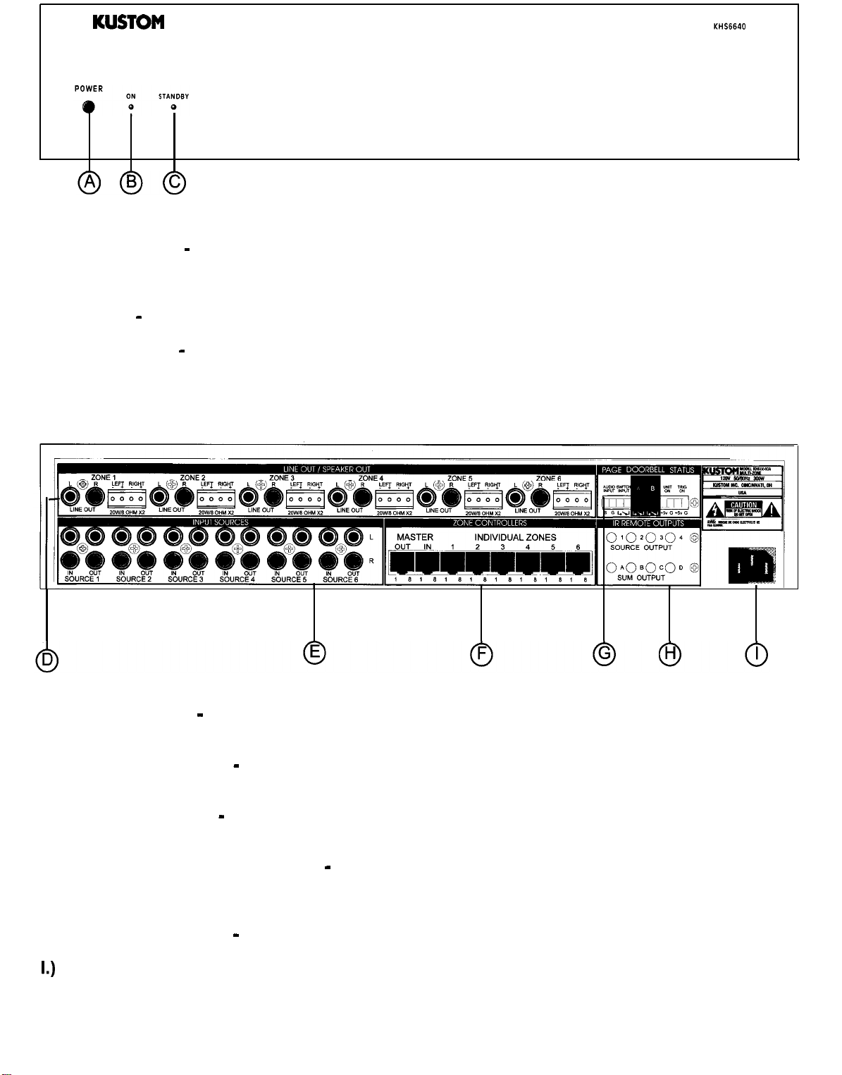
SIX-ZONE AMPLIFICATION SYSTEM
MODEL KHS6640
A.) Power Switch - Left on, the KHS6640, when not being used, will go into a “sleep” mode, ready
to turn back on when an input signal is applied from any of the six sources. In the off position, the unit
will not function.
B.) On LED - with the power switch on, this LED indicates that the unit is powered up and “awake”.
C.)
Standby LED - this LED indicates that the unit is plugged into the wall and is in the “sleep” mode.
It remains on as long as the unit is plugged into the wall.
D.) Output Section - this section is the output section. It provides the speaker terminals and line
outputs.
E.) Distribution Section - this section is the line level input/output section. It provides the inputs from
your sources and the outputs for stacking additional units.
F.) Controller Section - this section is where the wall controller in each zone connect. This section
includes the “party” mode master controller input.
G.) Paging/Control Voltage Section - this section is the Paging and Control Voltage Input and output
section. It provides the inputs from your phone system, door bells (front and back). It also has a control
voltage input and output for the unit controlling or being controlled by additional equipment.
H.) Infrared (IR) Section - this is the IR section. It provides outputs for the IR emitters.
I.)
AC Power Cord -this
is where the AC power cord connects to the unit. It is a detachable 3 prong
I.E.C. plug.
Page
2
Page 3
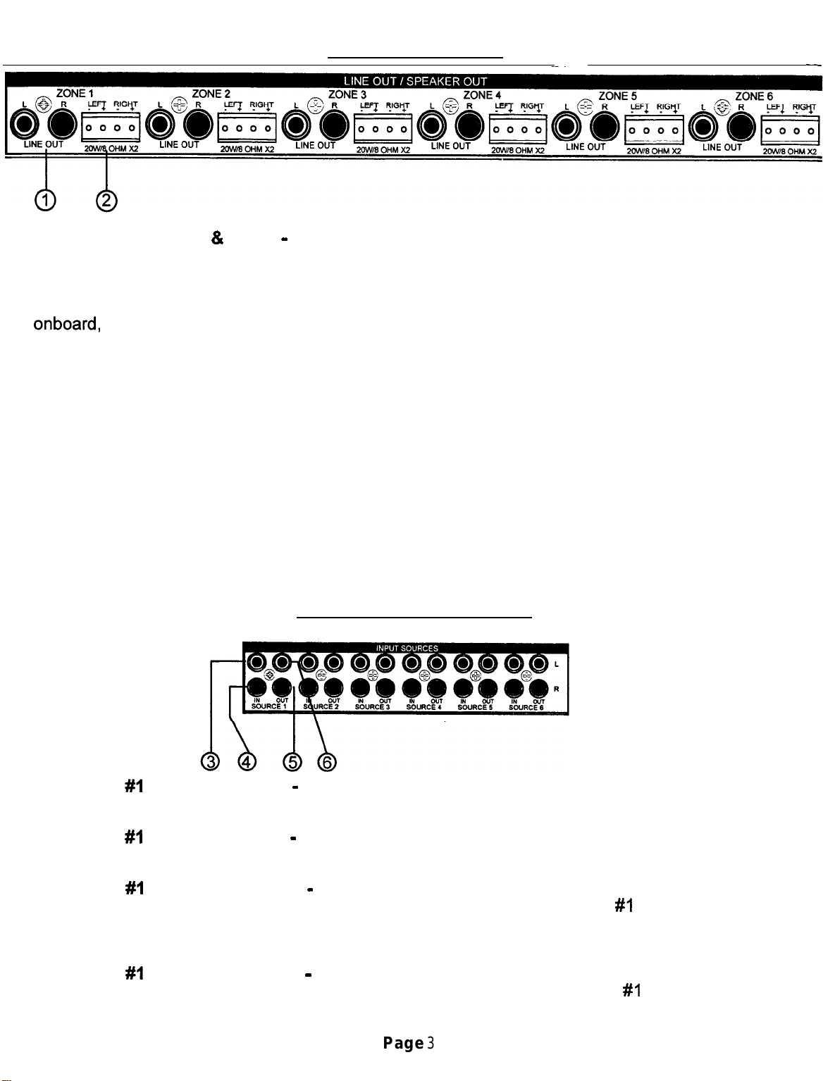
OUTPUT SECTION
SMARTHOME.COM™ 1-800-SMART-HOME 949-221-9200 http://www.smarthome.com Order #8270C
1.) Line Outputs (Left & Right) - these are dual RCA line outputs to go to additional amplifiers or
to powered sub-woofers. The white one is for left channel and the red one is for right channel. These
outputs will react to the volume controllers for each zone. Any changes made to these will follow
through to these outputs.
If you need additional speakers, say for a deck or large family room and require more power than
onboard, simply take these outputs and plug into the larger amp and hook those speakers up and
you are set to go.
If you want to run sub-woofers in a zone, you can use powered sub-woofer systems or an additional
amp to power them as in above explanation.
2.)
Speaker Connectors -these
made. First determine which individual wire is ground (negative) and the other being the signal
(positive) of your speaker wire. The detachable speaker connectors are labeled as L- (left negative);
L+ (left positive); R- (right negative); R+ (right positive). There are small set screws on this connector
to allow solderless connections to be made. We suggest using a straight blade Jeweler’s screwdriver
to easily make this connection.
These speaker outputs are rated at 20 watts RMS a side into an 8 ohm load. Stay within that ohm
rating. This will be more than adequate power for most of the in-wall speakers on the market.
connectors are where the speaker connections for each zone are
-
These connectors are then duplicated for the additional five zones and are identical in nature.
DISTRIBUTION SECTION
3.)
Source #I Left Input (White) - this RCA input will accept any standard line level source such
as CD, Receiver, Tuner, DSS, TV audio and more. It connects the left channel.
4.) Source #I Right Input (Red) - this RCA input will accept any standard line level source such
as CD, Receiver, Tuner, DSS, TV audio and more. It connects the right channel.
5.) Source #I Left Output (White) - this RCA output will send a line level signal out, an exact copy
of that source signal, from the signal plugged into the left channel of source
stacking additional KHS6640 units together. This provides an ultra clean audio distribution amplifier
for signal clarity.
#I
inputs. It is used for
6.)
Source #I Right Output (Red) - this RCA output will send a line level signal out, an exact copy
of that source signal, from the signal plugged into the right channel of source
These connectors are then duplicated for the additional five sources and are identical in nature.
Page
3
#I
inputs.
Page 4
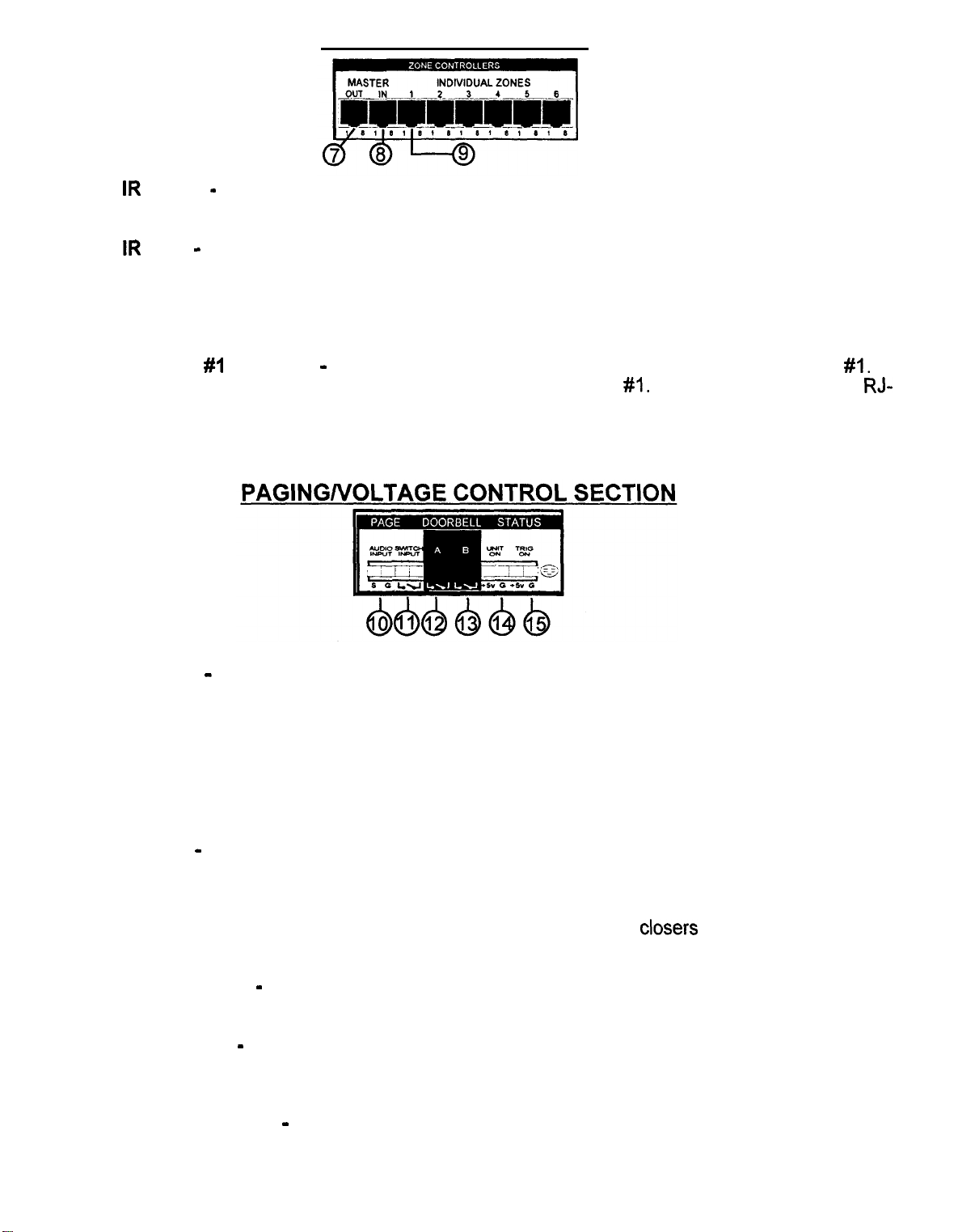
CONTROLLER SECTION
SMARTHOME.COM™ 1-800-SMART-HOME 949-221-9200 http://www.smarthome.com Order #8270C
7.) Master IR Output
-
this connector allows the “party” mode to apply to multiple units if additional
units are added.
8.) Master IR Input
-
this is for the “party” mode controller. This controller should be located near
the unit and sources. It will override all zone controllers and select a source which will then play in
all zones. This mode is used for playing the same background music in all zones such as during a
party. The individual wall controllers still have the ability to select a different source after the party
mode is engaged. It uses a standard 8 pin RJ-45 connector.
9.)
Individual Zone #I Controller
The signals from this wall controller control all the functions in zone
-
this connector hooks up the wall controllers used in zone
#I.
It uses a standard 8-pin
45 connector.
This connector is duplicated for the remaining 5 zones and function exactly the same.
#I.
RJ-
-
10.) Audio Inputs
this is an audio sensing circuit and accepts the signal from an external phone
system or a pre-amplified microphone (i.e.: a mixer output), that has the capability of sending a page
signal from the master phone unit. The signal from this phone system will mute whatever source is
playing in all zones and allow the person speaking to page into all zones simultaneously and make
their announcement. When the signal is disengaged, the music will return to the previous level. Even
zones that are not currently on will “open” and allow the announcement to be made. Inside the unit
is a master DIP type switch which allow the installer to turn off the paging and doorbell override. This
is especially suited for a nursery. Pin 1 is for signal and pin 2 is for ground.
11.) Switch Inputs
-
this input is designed for older systems like intercoms that require a push to talk
“latch” mode contact before the audio signal can pass through. This is a “hard” bypass of the audio
sources. This can act as a whole house mute as well.
12.) Front Doorbell Input -this input takes the signal from the contact
closers
from the front doorbell
transformer. When engaged, the source signal mutes and a distinctive chime (on board) plays through
the speakers, It will even play through zone speakers that aren’t on unless locked out.
13.)
Back Doorbell Input
-
same as above but with a separate distinctive chime sound so you can
differentiate between the doors.
14.) Control Voltage In
-
this allows an external sub system that sends a control voltage output to
this system to power up the unit from the “sleep” mode. This signal can be from 5 to 12 volts D.C.
The front panel power switch must be on for this to work.
15.) Control Voltage Output
-
this output sends a constant 5 volt D.C. signal out to trigger ancillary
equipment when the unit is powered up. When the unit goes into the “sleep” mode, this voltage stops.
Page
4
Page 5
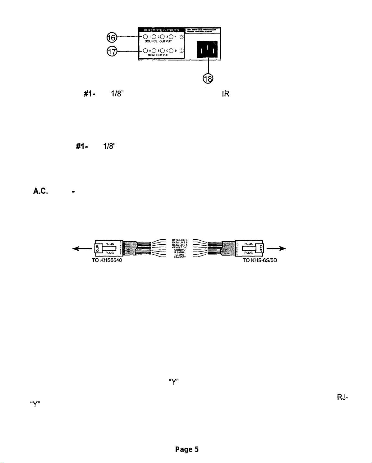
INFRARED (IR) SECTION
SMARTHOME.COM™ 1-800-SMART-HOME 949-221-9200 http://www.smarthome.com Order #8270C
16.) Source Output #I
-
this
q/8”
2 conductor jack is from the
IR
emitters and are “locked” source
specific. This is useful in the instance, if you have 2 or more of the same brand CD player, since the
same IR command will work on both, this ONLY sends the IR command to this particular source.
Nearly any brand of emitter will work. There are four source specific IR jacks.
This connector is duplicated for the remaining 3 zones and function exactly the same as the first one.
17.)
Sum Output #I
-
this
l/8”
2 conductor jack is from the IR emitters and are summed across the
IR buss. This will allow normal operation of different components that don’t share the same IR
commands. There are four sum outut IR jacks.
This connector is duplicated for the remaining 3 zones and function exactly the same as the first one..
18.)
AX.
Power
-
this is where the AC power cord connects to the unit. It is a detachable 3 prong
I.E.C. plug. Never remove the ground lug on the plug or electrical shock and damage to the unit could
result.
INSTALLATION NOTES
WIRING DIAGRAM FOR REMOTE ROOM CONTROLLERS
l
Use Category 5 8-conductor cable. It is not necessary for it to be shielded but be careful with
your cable runs. Avoid running a tight parallel with A.C. wiring. Be careful if stapling the wire to secure
it in place.
l
Use high quality RJ-45 connectors and make sure you use a high quality crimp tool. The
connection of the RJ-45 connectors is crucial in making the system work properly.
l
Avoid tight or sharp turns near the ends of the RJ-45 connections to the controller or main
units. This can put excessive strain on already small wires.
l
Note when stacking multiple units: Audio sources connect via the distribution outputs and wall
controllers.combine via the Master Controller Out jack. Make a short jumper and connect to the second
unit’s Master Controller In jack to allow the “party” mode master controller to access all zones. For
the IR Emitters, we strongly suggest using a
“Y”
adapter for the emitters that attach directly from the
sources and then to the second unit’s IR outputs. This then allows the source specific functionality
to be utilized by the second KHS-6640. An additional controller can be run per zone by using a
45
“Y”
adapter before the main unit.
Page 5
RJ-
Page 6

Master In/Out:
SMARTHOME.COM™ 1-800-SMART-HOME 949-221-9200 http://www.smarthome.com Order #8270C
The master controller input will accept a seventh
control for the entire system. If “Source 1” is selected on this controller, all zones will switch to Source 1.
If volume up is pressed, all zones will go up and visa versa volume down will lower all zones. If mute is pressed,
any zones active will be muted.
the “Master Out” jack can be connected to the “Master In” on a second KHS-6640 to allow master control of
2 units (12 zones).
Individual rooms then can override this and return to a local zone mode. this way individual zones can be
changed to suit the listener in a particular zone.
Unit On:
When the “On” LED is lit, there is a
such as relays or digital switches. This voltage is switched off when the “Power” button is out or the KHS-6640
is in the “sleep” mode such as with no sources playing.
Trig On:
By applying
present, the KHS-6640 will return to the “sleep” mode when the voltage is removed.
Using Multiple KHS-6640 Units:
Up to 3 KHS-6640 units may be wired together to provide 18 zones of listening pleasure. First connect all
sources into the first KHS-6640 and use the “Source Outs” to connect to the “Source Ins” on the second unit.
Then use the Source Outs on the second unit to connect into the Source Ins on the third unit. Next, using
adapters
Lastly, any connections made to page/doorbell status connectors must also be made to the other KHS-6640’s.
+5v
(2-l/8”
to
+12v
DC to thyese pins, the KHS-6640 can be temporarily “awakened”. If no sources are
plugs to I-
l/8”
+5v
DC applied to these pins that can be used to control any equipment
jack), connect all emitter outputs of the KHS-6640 to proper source emitters.
KHSGS
controller. This controller will then become a master
Y-
Adding More Audio Power to the KHS-6640:
If you need more audio power in a zone, simply attach an RCA cable in between the “Line Out” jacks and the
inputs of an external power amplifier. This allows virtually unlimited volumes to be obtained. (Multiple outdoor
speakers are a prime example).
Section 4: Special Wiring Schemes:
The following connections are made to the KHS-6640 via the 12 pin terminal block located on the back of the
unit. Cat-5 wire or doorbell wire is perfectly suitable for all of these connections.
1. Page/ Doorbell Status:
Paging:
Input” will accept any audio signal and will mute the sources and play the page audio automatically. The page
sensitivity and level adjustable via trim pots located inside the KHS-6640 (see fig. 1). Additionally, there are
two pins labeled “Mute Input”. When a DC voltage
will also be muted.
Doorbell: The KHS-6640 has two built-in and distinctly different doorbell sounds
Either doorbell can be triggered by attaching wires from the houses doorbell transformer (switch side) to the
terminals on the KHS-6640 labeled “Doorbell A or B”. Any voltage from
doorbell. This allows this feature to be used with most types of existing doorbells. Doorbell volume can be
adjusted via a trim pot located inside the KHS-6640 (see fig. 2). The paging and doorbell features can be
further customized in each zone. You can disable the page/doorbell feature in a zone by setting both slide
switches on that zone board to “Off”. This might be of use in a nursery, for instance. You can set a zone to
only mute the sources, but not play the page or doorbell by setting “Switch” to “On”, but setting “audio” to “Off”.
Finally, you could set “Switch” to “Off’ and set “Audio” to “On”. This would allow the page or doorbell audio
to mix with the source audio (see fig. 3).
The 6640 has two ways to allow external paging to be amplified through the it. the jacks labeled “Audio
(+5v
to
+12v)
is applied to these pins the source audio
‘i”ding”
5v
to 24v AC or DC will trigger the
and “ding dong”).
Telephone Entry Systems:
(Channel Vision or similar)
The
KHS-6640 is well suited to be integrated into a telephone entry system such as the Channel Vision TE-
100. With these systems you can page from any phone in the house. Trigger to doorbell or mute the system
in some or all zones. Please consult their owner’s manuals for operation.
Page
7
Page 7

KHS 6640 Installation Manual
SMARTHOME.COM™ 1-800-SMART-HOME 949-221-9200 http://www.smarthome.com Order #8270C
Recommended Cables:
Category-5 or Category-3
164
or (2) 16-2 speaker cables.
To keep the installation process as simple as possible for first time users, please follow these simple steps. These instructions
are written assuming that you are using the
involving teaching the controller ir commands.
Please refer to the KHS-6640 Reference Manual for additional steps.
Section 1: Installation of Controller Cables and Speaker Cables.
1. Controllers should be located between wall studs and at the same height as light switches. Locating controllers beside light
switches is o.k. as long as the Cat-5 cable and AC wiring (romex) are not bundled together and in their own box. Each controller
cable is “home run” between each zone and the KHS-6640 unit.
2. The ends of the Cat-5 cable are terminated with RJ-45 crimp on connectors (unkeyed). The proper wiring is the same as
standard phone company wiring: pin 1 to pin 8, pin 2 to pin 7, pin 3 to pin 6, pin 4 to pin
available from your local distributor.
3. Each speaker cable is also “home run” between each speaker and the KHS-6640 unit. One pair of 6-8 ohm speakers per zone
is recommended. The speaker wires are attached to the green 4-pin terminal blocks located in the back of the 6640 (these are
easily removable for ease of installation). Please observe proper polarity and left-right orientation.
4. All controllers and speakers can then be hooked up to their proper cables
Wiring Diagram
(4
twisted pair stranded), shielded or unshielded.
KHSGS
controller. If you have the
KHSGD
but not to the KHS-6640 yet.
controller. There are additional steps
S,...etc.
(see
fig.1).
Cable testers are
WIRING DIAGRAM FOR REMOTE ROOM CONTROLLERS
Section 2: Installation of the 6640 unit.
1.
Place the 6640 in its permanent position in a rack or on a shelf. This unit generates large amounts of heat so please remember
to allow for adequate ventilation.
2. Attach the AC power cord to the unit and plug the cord into the wall.
At this point the “Power” switch should be off. The “Standby” LED should be on but the “On” LED should be be off.
3. Select which device will be source 1 and attach the audio outputs from it to the audio in terminals on the KHS-6640. At this
point place this source into “play” so that you will have audio to monitor.
4. Now attach the speaker connector for zone 1 to the KHS-6640 (you decide which room will be which zone, and you should
write these assignments down for future reference).
5. Now press the “Power” button in to activate the KHS-6640 (you should now see both the “ON” and the “STANDBY” LED’S lit
on the KHS-6640.
6. Now attach the zone 1 controller to the zone 1 controller input on the KHS-6640.
7. Now go to zone 1 controller. If the source 1 equipment is pla
that indicates the KHS-6640 is powered up and 1 of 6 green L
are not lit, Try pressing the “mute” button. This button mutes the source audio in this particular zone). Select the proper source
by pressing the corresponding button on the left of the controller. press the “volume up” button to adjust the listening level.
8. If you do not have sound, please review steps l-7. If you do have audio please attach the remaining sources to the KHS-6640.
If all sources are playing, you should now be able to select whichever source you want to listen to. A more detailed description
of controller operation is in the
9. Once you are comfortable with the operation of one zone you can proceed to wire the other zones in the same way.
Section 3: Infrared Repeater:
The KHS-6640 has a built-in IR repeater system. This works by sensing any ir commands issued by an IR remote in any zone
and passing it through the Cat-5 cable and into the
KHS-6640. Any IR emitters plugged into the jacks will flash depending which source is selected and which jack that emitter is
plugged into. The jacks labeled “Source Outputs
‘Sum Outputs A-D” will flash when any source is selected.
1. Plug an emitter into “Source 1” emitter out. Attach the flasher end to the face of the source equipment, making sure to cover
the ir sensor window.
2. You should now be able to select Source 1 on the keypad and, using that sources’ remote, control that source. Make sure
you point the remote at the rectangular ir window located at the top of the KHSGS.
KHSGS
operation manual.
KHS-6640
l-4”
will flash only when that particular source is selected. The jacks labeled
ing you should see two LED’s lit on the controller. The red led
2
D’s that indicate which source is selected (if the green LED’s
unit. From here it goes to the emitter outputs on the back of the
*SPECIAL NOTE*
IR receivers in consumer electronics operate at different modulation frequencies. The most common is 38khz (kilohertz). However,
most satellite receivers operate at 56khz and some equipment operates at 32khz. Still other equipment is not even compatible
with this type of IR system. The KHS-6640 will work with the majority of consumer audio/video equipment. However, some models
will not operate. It is up to the installer to determine compatibility.
Page 8
Page 8

1.)
SMARTHOME.COM™ 1-800-SMART-HOME 949-221-9200 http://www.smarthome.com Order #8270C
IR Sensor
Source Selectors (1 - 6)
2.1
Source LED ( 1 - 6)
3.)
Power Status LED
4.1
Mute Button
5.1
Volume Up
6.1
KHS-6S
CONTROLLER
7.) Volume Down
1.) IR Sensor -
this is an Infrared Sensor window. We suggest you aim the external remote control
directly at this window to pass on commands back to and through the unit.
2.)
Source Selector Buttons (1 - 6) -these
buttons will select the source you want to listen to.
Individual key caps (supplied with the unit) will allow you to “customize” the source selections. These
can be: CD, Receiver, Tape, DSS, TV or whatever combination you wish.
3.) Source Selection LEDs (1 -6) -these
Light Emitting
Diodes (LED) will light up next to the selected
source to let you know the selection was made.
4.) Power Status LED
-
this LED indicates the power status of the system. Lighted, the system is on
and ready. Off, the system is not engaged.
5.) Mute Button -this
muting
6.)
the system such as to take a phone call or listen to someone speaking in another room.
Volume Up
-
button will instantly stop the audio through the system. It is used for temporarily
this raises the local zone volume up at a rate of 2-4 db per
I/IO
the control and the volume goes up quickly.
second. Hold down
7.)
Volume Down
-this
lowers the local zone volume down at a rate of 2-4 db per
l/IO
second. Hold
down the control and the volume goes down quickly.
Page 10
Page 9

KHS-6D
SMARTHOME.COM™ 1-800-SMART-HOME 949-221-9200 http://www.smarthome.com Order #8270C
The left side of this controller is identical to the KHS-6S consult last page.
CONTROLLER
84
Reset
16.)
Numeric Entry
” I\
17.)
Enter Button
Clear
14.) Learn Button
15.) IR Sensor LED
8.) Reset - this resets the local zone controller if an IR command “locks up” the zone. It will not erase
the local zone memory. It will just send a local clear command.
‘x”.+‘
\ ._. “.
l^. .“. ,. ,,
18.)
Macro Button
19.)
Skip Backwards
20.)
Skip Forwards
21.)
Power On
22.)
Reverse
9.)
Clear - this button has 3 modes: a.) device mode - will clear learned commands from the local
zone memory. If you press clear and then say source selector
that page of memory will be erased. b.) storage mode
and reprogrammed. c.) macro memory mode - this will allow you to reprogram a individual macro key
(0 -9).
(This is a permanent erase function, so be careful with this command.)
10.) Clone RX - this button will place the controller into a “ready to receive commands” mode. This
is the learning mode. When setting up the system initially, place all but one controller in this mode and
use the one master controller to teach the local zones their commands. The clone/learn LED will light
and stay on. When the data is received correctly, the red LED will go out and the green OK light will
go on.This process takes between 6 and 8 minutes.
11.) Clone TX
is the teaching mode. When setting up the system initially, place one controller in this mode and use
it as a master controller to teach the other local zones their commands. The clone/learn LED and OK
LED will stay on. When the data is transmitted correctly, the red LED will go out and the green OK
light will flash then go off. This process takes between 6 and 8 minutes.
12.) Clone/Learn LED -this LED will let you know the status of transmit and receive during the learning
or teaching processes.
13.) OK - this LED will also let you know the progress of the learning/teaching processes.
14) Learn Button - this button puts the controller into a learning mode.
-this button will place the controller into a “ready to transmit commands” mode. This
-
this will allow any individual key to be erased
#I
then the commands associated with
15.) IR Sensor - use this IR window when teaching a controller new IR commands with an external
remote.
Page 11
Page 10

I
SMARTHOME.COM™ 1-800-SMART-HOME 949-221-9200 http://www.smarthome.com Order #8270C
This
pacle
is for information onlv - Consult
Your
Installer for Application
1
IR Emitter Modulation Frequency - these are
factory set to give optimum preformance of the
emitters. Factory setting is
40KHz.
Range is 32 KHz full CCW to 65 KHz full CW.
_lix-_-...
_...” __..I_l”-_” “_,“_.~. I ,--,,,-,1-- .~““l-_-_- .._. ___i
.,-._
sa::
.-.” .“~~, ._“““______~~
“4’ :‘:5 ;a.$,
’
Page Sensitivity - set to match
page source output for VOX
function. Factory setting
-2Odb.
IR OUTPUT PC BOARD (Fig.
,, .
#I)
Doorbell Level - adjust to
doorbell chime to appropriate level.
Factory setting
-1Odb
DOORBELL/PAGING PC BOARD
(Fig.
\
Page Level - adjust to set page level to appropriate
level. Factory setting is -1 Odb.
onboard
#2)
,Audio -
disables doorbell and
page audio. Factory setting is
“on”.
Switch - mutes sources when
doorbell or page is engaged.
Factory setting is “on”. Set to “off
if you don’t wish to have sources
muted when
dootbell
or page is
activated (such as a nursery, etc.).
F
If you want one zone to not be interrupted by paging or the dorrbell, set both switches to “off”.
If you wish to have one zone muted without the doorbell or paging audio set audio switch to “off”.
If you want to leave the source audio in place and have the page and doorbell audio superimposed over
the top of it, set
switch
to “off”.
Page 9
Page 11

KHS-6D
SMARTHOME.COM™ 1-800-SMART-HOME 949-221-9200 http://www.smarthome.com Order #8270C
16.) Numeric Entry Keys (0 - 9) - depending on the mode you are in these keys will allow direct
track access on a CD, an individual station on
the macro mode, these will allow direct access to your stored macros.
17.) Enter button - working in conjunction with the numeric keys above, this button will allow you
to address larger numbers quicker. For instance, if you are looking for track # 23 on a CD, you press
this 2 and then 3 and enter. This will allow access to DSS and multi-disc changers.
The following buttons are completely programmable. They may be reprogrammed to any function
you want depending on the source. In fact, they can be ANY IR related command. It does not even
have to pertain to the source units.
CONTROLLER
n/
or DSS, or a station on a tuner, etc. If you are in
(cont’dl
18.) Macro Button - this button has it’s own section. Please refer to the
section in this manual.
19.) Skip Backward - this button skips or searches backward. For instance if your source is a CD,
it will skip back to the beginning of the track that is playing, then if pushed again, it will skip back to
next track previous to the one you are on. Repeat as necessary. This is a programmable button. It
may be reprogrammed to any function you want depending on the source.
20.) Skip Forward -this
will skip forward to the beginning of the next track, then if pushed again, it will skip forward to the
next track beyond that one. Repeat as necessary. This is a programmable button. It may be
reprogrammed to any function you want depending on the source.
21.) Power On - this button will turn on the source power switch from whatever zone you are in. It
can be programmed to cycle between on and off. When you program this button, press it once and
transmit the code for power on, then press it again for the command to power off. When pressed it
will toggle between on and off positions.
22.) Reverse - this button will scan backwards within a track if you are in the CD source mode, or
move down the dial in a tuner source mode. This is a programmable button. It may be reprogrammed
to any function you want depending on the source.
23.)
Forward - this button will scan forwards within a track if you are in the CD source mode, or
move up the dial in a tuner source mode. This is a programmable button. It may be reprogrammed
to any function you want. Pressing and holding it down will move
it quicker. This is a programmable button. It may be reprogrammed to any function you want depending
on the source.
button skips or searches forward. For instance if your source is a CD, it
.
MACRO PROGRAMMING
.
24.) Play - this button in the CD or tape mode will start playing the appropriate device. This is a
programmable button. It may be reprogrammed to any function you want depending on the source.
25.) Pause - primarily for tape or CD modes, this button will stop the music and wait in the same
place until the play button (or other function), is engaged. This is a programmable button. It may
be reprogrammed to any function you want depending on the source.
26.)
Stop -this
It may be reprogrammed to any function you want depending on the source.
button will stop the CD or tape player in those modes. This is a programmable button.
Page 12
.
Page 12

Programming the
Page 13
SMARTHOME.COM™ 1-800-SMART-HOME 949-221-9200 http://www.smarthome.com Order #8270C
The
KHSGD
This enables the individual programming and use of multiple functions for all of your source components.
1) Press the “learn” button on the controller. The left, red “Clone/Learn” LED will begin flashing.
2) Press the source device button to be programmed.
3) Press the numeric or function key you wish to program on the right side of the controller. The red
“Clone/Learn” LED will stop flashing and glow continuously.
4) Hold the source remote control IR emitter 1” to 2” from the
corresponding function key on the source remote. After a short period of time, the right, green “Ok” LED
will glow indicating the acceptance of that command. At this point the controller will return to a flashing red
LED.
indicates an error with that command. Should this occur, clear it and try reentering that function.)
5) Repeat steps 2-4 for the next desired function.
6) When all the desired functions for a particular source have been programmed, we suggest you “reset”
the keypad.
7) Repeat steps l-6 for the remaining functions.
(all of the numeric and function keys will learn any ir code. Functions programmed into the controller are
solely at the discretion of the installer.)
controller is designed to learn and store IR codes for virtually any piece of audio/video equipment.
Programming Individual Functions
It is now ready to be taught the next command for that source. (a solid red and green LED simultaneously
KHSGD
Cloning
Controllers
“IR
Sensor” on the controller and press the
The
KHSGD
to up to five additional controllers within an installation.
Once one of the controllers is programmed, go to the other controllers and press the “Clone RX” button.
then return to the programmed controller and press the “Clone/TX” button. The green LED will remain lit
while the cloning process is in progress. When the process is complete, the green LED will turn off. This
should take about 8 minutes. It is a good idea to then “reset” all of the controllers.
Now all the controllers share identical information. The nonvolatile memory will remain regardless of whether
the controllers are plugged into the system. Using the “Clear” button can clear the controller memory. to
erase an entire page of memory, simply press the “Clear” button and then a “Source Device” button. By
pressing a source device button, the “Clear” button and one of the programmed function buttons will erase
a single function. Once cleared, a controller or individual function can be reprogrammed.
has a cloning feature that will allow you to down load the information stored in one controller
-
Page 13

MACRO PROGRAMMING
SMARTHOME.COM™ 1-800-SMART-HOME 949-221-9200 http://www.smarthome.com Order #8270C
The KHS-6D has 16 programmable macro memories. It will automatically transmit a series of 20
commands deep.
To enter the macro mode
-
press macro and the either the 0 through 9 buttons OR the device source
keys (l-6). You can insert a delay time from 1 to 99 seconds between steps (the default is
suit their specialized needs. To program in time delays, press the appropriate button and hold it from
1 to 99 seconds then input the next command.
Here is an example of how to set a macro.
The list of things you want to accomplish are:
1.) Power on receiver
2.) Set receiver input to Aux In
3.) Power on LaserDisc device
4.) Open LaserDisc Drawer
5.) Close drapes
6.) Dim lights
7.) Select Play on LaserDisc
Press Learn then Macro button to enter the Macro learning mode. The Red LED blinks and you should
input either 0 to 9 or device button (l-6).
1.) Press source button that is programmed to receiver
2.) Press Power Button to power up receiver
3.) Press Aux In on Receiver
4.) Select LaserDisc
5.) Power on LaserDisc device
6.) Open LaserDisc Drawer
7.) Close drapes (assuming drapes are under IR control)
8.) Dim lights (assuming the lights are also under
IR
control)
9.) Select Play on LaserDisc
5
sec.) to
Press the learn button or wait 15 seconds for it to return to normal. The red LED turns off.
\
To utilize the Macro Mode- press the macro button (it will only wait for 2 seconds for a second button
to be pressed) then press either numeric button (O-9) or source button (l-6) to engage a pre-programmed
macro.
To clear a macro out of memory, press clear then macro and then the key with the memory you wish
to erase. It is a permanent erase, so make sure you are careful. If no key is pressed within 15 seconds,
the unit will exit the clear mode and return to normal operation.
Page 14
I
Page 14

dendum
SMARTHOME.COM™
1-800-SMART-HOME
949-221-9200
http://www.smarthome.com
Order #8270C
Programming a wireless remote using the KHS6S Wall Controller
Remove the Decora cover plate, and controller face plate.
1.
Place your wireless remote in learn mode. (learn LED should begin flashing on the
2.
KHSLRC model learning remote control)
3.
Select the device bank button to program (i.e. TV, VCR, Tuner, Aux, etc.) on the
wireless remote.
Select the button to be programmed on the learning remote. (i.e. l-6, mute, or volume
4.
up and down)
5.
6.
7.
.While
holding the wireless remote within 2” from the top, center, clear LED on the
KHS6S (this is the controller IR emitter), press the command button on the KHS6S
Controller you wish to program into the wireless remote.
The wireless remote should then accept the KHS6S command. (the green “OK” LED
will then light on the KHSLRC model learning remote)
Once you have programmed the source device, volume up and down, and mute
functions for the first source device, you can then repeat steps 4-6 for the remaining
five source devices, until you have programmed all six sources for the KHS6640
amplifier.
*Please note when programming it is best to hold the KHS6S button until the wireless
remote has indicated that it has learned the command.
 Loading...