

Kustom KHS6440 Owner's Manual
KHS6440 OWNERS MANUAL
POWER
SIX-ZONE AMPLIFICATION SYSTEM
STANDBY
ON
MODEL KHS6440
Six-Source, Four-Zone
Audio Distribution System
Congratulations on choosing the KHS6440 audio distribution system. The
Kustom Home Sound products offer unparalleled quality and performance at a
very affordable price. No other products in the industry offer as much flexibility,
ease of installation, and features to meet your needs.
The KHS6440 has 6 individual audio source inputs with a corresponding audio
out for linking with another 6440 or the KHS6640 amplifier. Each zone amplifier
is equipped with active line outputs for utilizing an additional amplifier for zones
that require additional power, as well as speaker outputs for clear, undistorted
audio to your in-wall speakers. A built-in IR routing system allows you to operate
CD players, satellite receivers, or any other equipment independently even
though the same manufacturer makes them and they respond to the same IR
codes. Your 6440 system may be controlled by the KHS6S, single gang controller,
or the KHS6D dual gang, programmable Controller for complete IR control of
your audio equipment from any room of your house.
Whether you are enjoying a movie on TV, relaxing to music at the end of the
day in your bedroom, listening to the evening news as you prepare dinner in the
kitchen, or entertaining friends on your deck, the Kustom Audio Distribution
Systems will enhance your lifestyle for years to come.
DANGER
EXPOSURE TO EXTREMELY HIGH NOISE LEVELS MAY CAUSE A PERMANENT
HEARING LOSS. INDIVIDUALS VARY CONSIDERABLY TO NOISE INDUCED HEARING
LOSS BUT NEARLY EVERYONE WILL LOSE SOME HEARING IF EXPOSED TO
SUFFICIENTLY INTENSE NOISE FOR A SUFFICIENT TIME.
THE U.S. GOVERNMENT'S OCCUPATIONAL SAFETY AND HEALTH ADMINISTRATION
(OSHA) HAS SPECIFIED THE FOLLOWING PERMISSIBLE NOISE LEVEL EXPOSURES:
DURATION PER DAY IN HOURS
8
6
4
3
2
1
1/2 HR. or LESS
SOUND LEVEL db FLOW RESPONSE
90
93
95
97
100
103
110
ACCORDING TO OSHA, ANY EXPOSURE IN THE ABOVE PERMISSIBLE LIMITS COULD
RESULT IN SOME HEARING LOSS. EAR PLUGS OR PROTECTORS IN THE EAR CANAL
OR OVER THE EARS MUST BE WORN WHEN OPERATING THIS AMPLIFICATION
SYSTEM IN ORDER TO PREVENT A PERMANENT HEARING LOSS. IF EXPOSURE IN
EXCESS OF THE LIMITS AS PUT FORTH ABOVE, TO INSURE AGAINST POTENTIALLY
HARMFUL EXPOSURE TO HIGH SOUND PRESSURE LEVELS. IT IS RECOMMENDED
THAT ALL PERSONS EXPOSED TO EQUIPMENT CAPABLE OF INDUCING HIGH SOUND
PRESSURE LEVELS, SUCH AS THIS AMPLIFICATION SYSTEM, BE PROTECTED BY
HEARING PROTECTORS WHILE THIS UNIT IS IN OPERATION.
IMPORTANT
1. Read all safety and operating instructions before using this product.
2. All safety and operating instructions should be kept for future reference.
3. Obey all cautions in the operating instructions and on the back of the unit.
4. All operating instructions should be followed.
5. This product should not be used near water i.e. bathtub, sink, swimming
pool, wet basement, etc.
6. This product should be located so that its position does not interfere
with proper ventilation. It should not be placed flat against a wall or
placed in a built-in enclosure that will impede the flow of cooling air.
7. This product should not be placed near a source of heat, such as a
stove, radiator, or another heat producing amplifier.
8. Connect only to a power supply of the type indicated on the back of the
amplifier near the power supply cord.
9. Do not break off the ground pin of the power supply cord.
10. Power supply cords should always handled carefully. Never walk or place
equipment on power supply cords. Periodically check cords for cuts or
signs of stress, especially at the point where the cord exits the unit.
11. The power supply cord should be unplugged when the unit is unused
for long periods of time.
12. If this product is to be mounted in an equipment rack, rear support
should be provided.
13. Metal parts and vinyl covering may be cleaned with a damp rag.
14. Care should be taken so that objects do not fall and liquids are not spilled
into the unit through the ventilation ports or any other openings.
15.This unit should be checked by a qualified service technician if:
A. The power supply cord or plug has been damaged.
B. Anything has fallen or been spilled into the unit.
C. The unit does not operate correctly.
D. The unit has been dropped or the enclosure damaged.
THIS APPARATUS SHALL NOT BE EXPOSED TO
DRIPPING OR SPLASHING. NO OBJECTS FILLED
WITH LIQUIDS SUCH AS VASES SHALL BE PLACED
ON THE APPARATUS.
TO AVOID ELECTRICAL SHOCK, DO NOT
DISASSEMBLE. REFER SERVICING TO QUALIFIED
PERSONAL ONLY!
CAUTION
RISK OF ELECTRIC SHOCK
DO NOT OPEN
CAUTION:
TO REDUCE THE RISK OF ELECTRIC SHOCK, DO NOT
REMOVE CHASSIS. NO USER-SERVICEABLE PARTS
INSIDE. REFER SERVICING TO QUALIFIED SERVICE
PERSONNEL.
AVIS: RISQUE DE CHOC ELECTRIQUE-NE PAS OUVRIR.
THIS SYMBOL IS INTENDED TO ALERT THE USER TO THE PRESENCE OF
UNINSULATED DANGEROUS VOLTAGE WITHIN THE PRODUCTS ENCLOSURE THAT
MAY BE OF SUFFICIENT MAGNITUDE TO CONSITUTE A RISK OF ELECTRIC SHOCK
TO PERSONS.
THIS SYMBOL IS INTENDED TO ALERT THE USER TO THE PRESENCE OF IMPORTANT
OPERATING AND MAINTENANCE (SERVICING) INSTRUCTIONS IN THE LITERATURE
ACCOMPANYING THE UNIT.
16. The user should not attempt to service this equipment. All service work
must be done by a qualified service technician for warranty repairs.
CAUTION
THIS AMPLIFIER HAS BEEN DESIGNED AND CONSTRUCTED TO PROVIDE
ADEQUATE POWER RESERVE FOR PLAYING MODERN MUSIC WHICH MAY
REQUIRE OCCASIONAL PEAK POWER. EXTENDED OPERATION AT
ABSOLUTE MAXIMUM POWER IS NOT RECOMMENDED SINCE THIS
COULD DAMAGE THE ASSOCIATED LOUDSPEAKER SYSTEM. PLEASE BE
AWARE THAT MAXIMUM POWER CAN BE OBTAINED WITH VERY LOW
SETTINGS OF THE MASTER VOLUME CONTROLS IF THE INPUT SIGNAL
IS VERY STRONG.
Kustom Inc., 4940 Delhi Pike, Cincinnati, OH USA
(800) 999-5558 Fax: (513) 347-2192 / www.kustom.com
SIX-ZONE AMPLIFICATION SYSTEM
MODEL KHS6440
POWER
ON
STANDBY
A B C
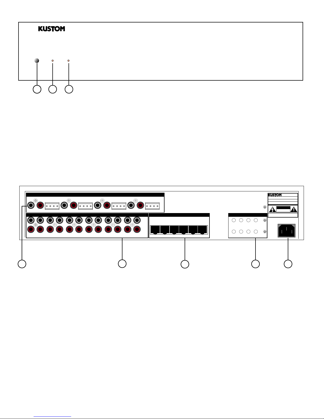
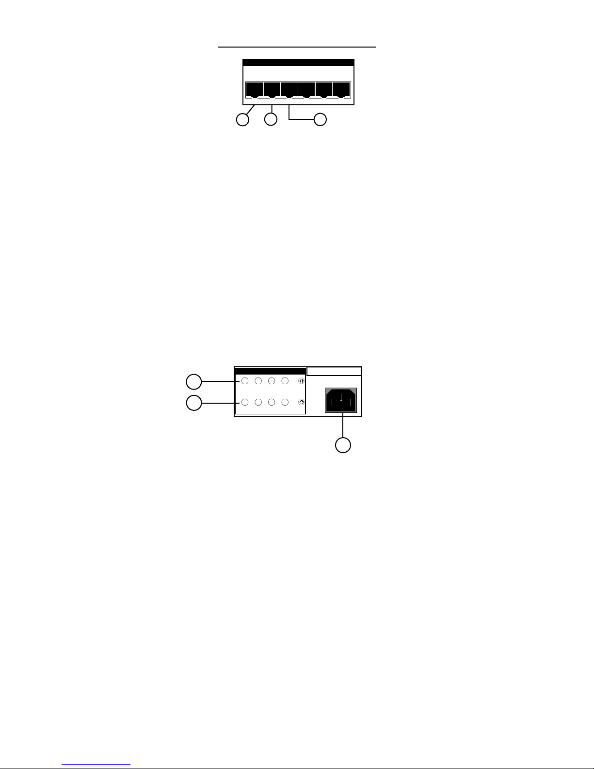
A.) Power Switch - Left on, the KHS6440, when not being used, will go into a sleep mode, ready
to turn back on when an input signal is applied from any of the six sources. In the off position, the unit
will not function.
B.) On LED - With the power switch on, this LED indicates that the unit is powered up and awake.
C.) Standby LED - This LED indicates that the unit is plugged into the wall.
ZONE 1
LEFT
L R
LINE OUT LINE OUT LINE OUT LINE OUT
IN OUT
SOURCE 1
RIGHT
- +
IN OUT
SOURCE 2
- +
LINE OUT / SPEAKER OUT
ZONE 2
INPUT SOURCES
IN OUT
SOURCE 3
LEFT
- +
LR
RIGHT
- +
IN OUT
SOURCE 4
ZONE 3
LR
IN OUT
SOURCE 5
LEFT
- +
RIGHT
- +
LR
IN OUT
SOURCE 6
ZONE 4
LEFT
RIGHT
- +
- +
20W/8 OHM X220W/8 OHM X220W/8 OHM X220W/8 OHM X2
L
R
ZONE CONTROLLERS
MASTER INDIVIDUAL ZONES
OUT
IN1234
IR REMOTE OUTPUTS
1
SOURCE OUTPUT
A2B3C4D
1 81 81 81 81 81 8
SUM OUTPUT
MODEL KHS6440A
MULTI-ZONE
120V 50/60Hz 300W
KUSTOM INC. CINCINNATI, OH
USA
CAUTION
RISK OF ELECTRIC SHOCK
DO NOT OPEN
AVIS:
RISQUE DE CHOC ELECTRIQUE-NE PAS OUVRIR.
WARNING:
SHOCK HAZARD - DO NOT OPEN.
D.) Output Section - This section is the output section. It provides the speaker terminals and line
outputs.
E.) Distribution Section - This section is the line level input/output section. It provides the inputs from
your sources and the outputs for stacking additional units.
F.) Controller Section - This section is where the wall controller in each zone connect. This section
includes the party mode master controller input.
G.) Infrared (IR) Section - This is the IR section. It provides outputs for the IR emitters.
H.) AC Power Cord - This is where the AC power cord connects to the unit. It is a detachable 3 prong
I.E.C. plug.
G HFED
Page 1
ZONE 1
L R
LEFT
- +
RIGHT
- +
LINE OUT / SPEAKER OUT
ZONE 2
LR
LEFT
- +
OUTPUT SECTION
RIGHT
- +
LR
ZONE 3
LEFT
- +
RIGHT
- +
ZONE 4
LR
LEFT
- +
RIGHT
- +
LINE OUT LINE OUT LINE OUT LINE OUT
20W/8 OHM X220W/8 OHM X220W/8 OHM X220W/8 OHM X2
1 2
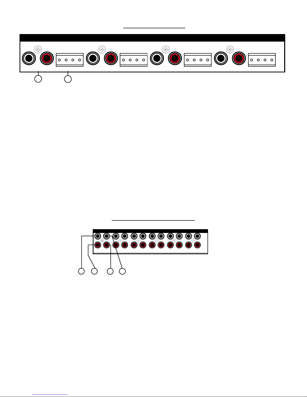
1.) Line Outputs (Left & Right) - These are dual RCA line outputs to go to additional amplifiers or
to powered sub-woofers. The white one is for left channel and the red one is for right channel. These
outputs will react to the volume controllers for each zone. Any changes made to these will follow
through to these outputs.
If you need additional speakers, say for a deck or large family room and require more power than
onboard, simply take these outputs and plug into the larger amp.
If you want to run sub-woofers in a zone, you can use powered sub-woofer systems or an additional
amp to power them as in the above explanation.
2.) Speaker Connectors - These connectors are where the speaker connections for each zone are
made. First determine which individual wire is ground (negative) and the other being the signal
(positive) of your speaker wire. The detachable speaker connectors are labeled as L- (left negative);
L+ (left positive); R- (right negative); R+ (right positive). There are small set screws on this connector
to allow solderless connections to be made. We suggest using a straight blade Jewelers screwdriver
to easily make this connection.
These speaker outputs are rated at 20 watts RMS a side into an 8 ohm load. Stay within that ohm
rating. This will be more than adequate power for most of the in-wall speakers on the market.
These connectors are then duplicated for the additional five zones and are identical in nature.
DISTRIBUTION SECTION
INPUT SOURCES
L
IN OUT
SOURCE 1
34
5
IN OUT
SOURCE 2
6
IN OUT
SOURCE 3
IN OUT
SOURCE 4
IN OUT
SOURCE 5
IN OUT
SOURCE 6
3.) Source #1 Left Input (White) - This RCA input will accept any standard line level source such
as CD, Receiver, Tuner, DSS, TV audio and more. It connects the left channel.
4.) Source #1 Right Input (Red) - This RCA input will accept any standard line level source such
as CD, Receiver, Tuner, DSS, TV audio and more. It connects the right channel.
5.) Source #1 Left Output (White) - This RCA output will send a line level signal out, an exact copy
of that source signal, from the signal plugged into the left channel of source #1 inputs. It is used for
stacking additional KHS6440 units together. This provides an ultra clean audio distribution amplifier
for signal clarity.
6.) Source #1 Right Output (Red) - This RCA output will send a line level signal out, an exact copy
of that source signal, from the signal plugged into the right channel of source #1 inputs.
R
These connectors are then duplicated for the additional five sources and are identical in nature.
Page 2
CONTROLLER SECTION
MASTER INDIVIDUAL ZONES
OUT
IN1234
1 81 81 81 81 81 8
8
7
9
7.) Master Output - This connector allows the party mode to apply to multiple units if additional
units are added.
8.) Master Input - This is for the party mode controller. This controller should be located near the
unit and sources. It will override all zone controllers and select a source which will then play in all
zones. This mode is used for playing the same background music in all zones such as during a party.
The individual wall controllers still have the ability to select a different source after the party mode is
engaged. It uses a standard 8 pin RJ-45 connector.
9.) Individual Zone #1 Controller - This connector hooks up the wall controllers used in zone #1.
The signals from this wall controller control all the functions in zone #1. It uses a standard 8-pin RJ45 connector.
This connector is duplicated for the remaining 5 zones and function exactly the same.
INFRARED (IR) SECTION
AVIS: RISQUE DE CHOC ELECTRIQUE-NE PAS OUVRIR.
WARNING: SHOCK HAZARD - DO NOT OPEN.
10
11
IR REMOTE OUTPUTS
1
SOURCE OUTPUT
A2B3C4D
SUM OUTPUT
12
10.) Source Output #1 through 4 - This 1/8 2 conductor jack is for the IR emitters and are locked
source specific. This is useful for instance, if you have 2 or more of the same brand CD player, since
the same IR command will work on both, this ONLY sends the IR command to this particular source.
Nearly any brand of emitter will work. There are four source specific IR jacks.
This connector is duplicated for the remaining 3 outputs and function exactly the same as the first
one.
11.) Sum Output #1 through 4 - This 1/8 2 conductor jack is for the IR emitters and are summed
across the IR buss. This will allow normal operation of different components that dont share the same
IR commands. There are four sum ouptut IR jacks.
This connector is duplicated for the remaining 3 outputs and function exactly the same as the first
one..
12.) A.C. Power - This is where the AC power cord connects to the unit. It is a detachable 3 prong
I.E.C. plug. Never remove the ground lug on the plug or electrical shock and damage to the unit
could result.
Page 3
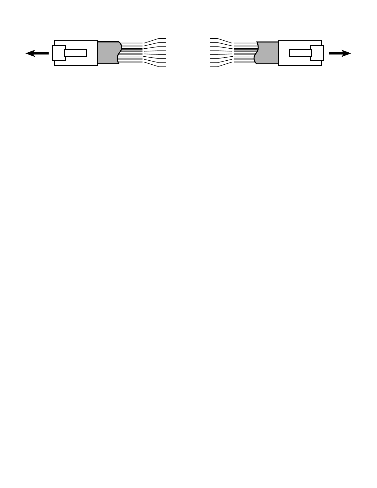
INSTALLATION NOTES
RJ-45
CLIP
PLUG
TO KHS6440
8
7
6
5
4
3
2
1
DATA LINE C
DATA LINE B
DATA LINE A
+5 VOLT D.C.
GROUND
IR SIGNAL
CLONE
STANDBY
1
2
RJ-45
3
4
5
6
7
PLUG
8
TO KHS6S/6D
CLIP
WIRING DIAGRAM FOR REMOTE ROOM CONTROLLERS
# Use Category 5 8-conductor cable. It is not necessary for it to be shielded but be careful with
your cable runs. Avoid running a tight parallel with A.C. wiring. Be careful if stapling the wire to secure
it in place.
# Use high quality RJ-45 connectors and make sure you use a high quality crimp tool. The crimp
of the RJ-45 connectors is crucial in making the system work properly.
# Avoid tight or sharp turns near the ends of the RJ-45 connections to the controller or main
units. This can put excessive strain on already small wires.
# Note when stacking multiple units: Audio sources connect via the distribution outputs. Wall
controllers combine via the Master Controller Out jack. Make a short jumper and connect to the second
units Master Controller In jack to allow the party mode master controller to access all zones. For
the IR Emitters, we strongly suggest using a Y adapter for the emitters that attach directly from the
sources and then to the second units IR outputs. This allows the source specific functionality to be
utilized by the second KHS6440. An additional controller can be run per zone by using a RJ-45 Y
adapter before the main unit.
Page 4
 Loading...