

Page 1

FILE: 091-60A.PMD
DATE: 07-30-09
INSTRUCTION MANUAL
REV. B
LOAD MANAGER MARK II
A START-UP AND SHUT DOWN LOAD SEQUENCER
AND AUTOMATIC LOAD SHEDDING SYSTEM
INTEGRAL RELAYS FOR 8 LOADS
WITH
MODEL #091-60A
INPUT: 12VOLTS, D.C.
OUTPUT LOAD: 30 AMPERES, MAXIMUM
3 YEAR WARRANTY
KUSSMAUL ELECTRONICS CO., INC.
170 CHERRY AVE., WEST SAYVILLE, N.Y. 11796
TEL: 631-567-0314 TOLL FREE: 800-346-0857 FAX: 631-567-5826 EMAIL: Sales@Kussmaul.com
Page 2

INTRODUCTION
The Load Manager Mark II is a device which:
1. Sequentially energizes and deenergizes relays which are mounted inside the unit at approximately
1/2 second intervals in order to reduce transients in a vehicle’s electrical system.
2. Detects when the vehicle’s electrical load is greater than the output of the alternator. When this
occurs, loads are sequentially deenergized until the alternator output is equal to the load.
The Load Manager Mark II contains the following features:
1. An electrical input which changes the Load Manager Mark II from an automatic load shedding
device to operation only as an automatic load sequencer.
2. An automatic override of the Load Manager Mark II which operates all the relays simultaneously by
connecting one input to ground.
3. An adjustable time delay from 2 to 16 seconds which prevents load shedding until the timeout
occurs. This timer starts when the Load Manager Mark II detects an overload. If the battery voltage
returns to normal before the timeout, the timer is reset and no loads are shed.
4. An indicator panel which includes a Power ON LED indicator and a Load Reduce indicator. This
provides the vehicle's driver with the information that the Load Manager Mark II is in operation and that
the loads are in the process of being shed.
5. Internally mounted relays that eliminate the need to supply separate relays in the vehicle. The loads
are wired to the relay contacts at the top of the unit using standard 1/4" quick disconnect terminals.
Each relay output is rated at 30 amperes maximum at 12 volts.
Page 3

LOAD MANAGER PROGRAMMING
Recognizing that priorities may change after an installation is made, the Load Manager Mark II is
designed so that the sequence of load removal may be easily altered.
At installation, the highest priority load is wired to relay K1 which is operated by terminal 3. The second
highest priority load is wired to relay K2, which is operated by terminal 4. A total of 8 relays, decreasing
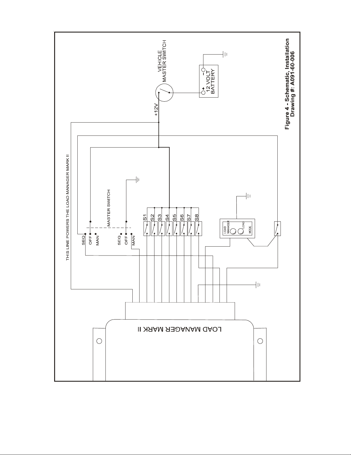
in priority are operated by terminals 5, 6, 7, 8, 9, & 13. See Figure 4 - Schematic, Installation.
Upon start-up, when the Load Manager Mark II operates as a sequential loading device, the loads are
applied in priority order with the highest priority first.
When the Load Manager feature is enabled and excessive electrical loads cause a drop in battery
voltage, the Load Manager Mark II will deenergize loads at approximately 2 second intervals starting
with the lowest priority. Loads will be removed until the voltage sensed returns to normal. The exact
interval between load removals depends on the degree of the overload and the capacity of the
batteries. With only a slight overload and large batteries the time interval is extended.
After installation the user may vary the priority by altering the switch setting from the BASIC SETTINGS
illustrated on Figure 3 - Relay Wiring Connections.
Caution: There are 5 switches, each with 5 levers. Only one lever on each switch my be in the
"ON" Position.
Each switch controls the operation of a relay. The actuation sequence of a particular relay
is controlled by the individual levers of each switch. Lever #5 is the lowest priority, while
lever #1 is the highest. It is thus possible to arrange the relay operating priority for the 5
lowest priority relays.
NOTE
The Load Manager Mark II contains the load switching relays. The
manual switches wired by the installer control the 12 volt supply to these
relays.
THE RELAY CONTACT CAPACITY IS 30 AMPS. DO NOT EXCEED.
Page 4

LOAD MANAGER SETTINGS
The standard setting on Load Manager Mark II may not be optimum for all applications. The
Configuration Switch , S6, sets the initial time delay and the initial shed voltage for the unit. On the
Configuration Switch, levers 1-3 are used for time settings. Levers 5 and 6 are for voltage
settings.
To prevent false voltage readings, the Load Manger Mark II, delays the shedding or adding of
loads. The initial delay time is factory set for four seconds. By adjusting levers 1-3 on the
Configuration Switch, the user may vary the initial time delay from 2 to 16 seconds. Figure 1 below
indicates how to alter the initial delay time.
Lever 1 Lever 2 Lever 3 Time Delay
on on on 2±.5 sec
Factory Setting
off on on 4±.5 sec
on off on 6±.5 sec
off off on 8±.5 sec
on on off 10±.5 sec
off on off 12±.5 sec
on off off 14±.5 sec
off off off 16±.5 sec
Figure 1
Configuration Switch, S6, InitialTime Delay Settings
Subsequent time delays for additional load shedding is factory set for 2 seconds and is not
adjustable.
Load Reduce will start at the Initial Shed Voltage. The Factory Setting, for the Initial Shed Voltage,
is 12.3VDC. For the first load to go off, the voltage must be 12.3 VDC or lower for the duration of
the time delay. Recovery, that is reapplication of a load will not occur until the voltage is .2 VDC
higher than the shed voltage. A time delay prevents the instantaneous operation of the output
relay. After shedding the first load the Load Manager waits 2 seconds before making a decision
to shed more loads. If the sensed voltage is .2 volts less than that at the previous shed point and
maintains this lower voltage for 2 seconds, the next load will be shed. This continues until
sufficient loads are shed so that there is no further decrease in sensed voltage. Figure 2 below
indicates the switch settings required to vary the Initial Shed Voltage. Loads are reapplied when
the voltage rises and is maintained for a suitable time.
Switch 4 Switch 5 Initial Shed Voltage
Factory Setting
on on 12.30±.1
off on 12.15±.1
on off 12.00±.1
off off 11.85±.1
Figure 2
Configuration Switch S6, Threshold Voltage Setting
CAUTION
Changes to Configuration Switch, S6, will only take effect during power up. Remove power from
pin one of Load Manager and reapply to change the setting on the Load Manger Mark II.
Page 5

1
2
3
5
6
7
8
4
9
101112
13
14
Figure 3 - Relay Wiring Connections
K1
N.C.
K2
N.O. N.C.
COM
N.O. N.C.
COM
K3
N.O.
COM
K4
N.C.
N.O.
COM
HIGHEST PRIORITY
K5
N.C.
K7
N.O.
COM
N.O. N.C.
COM
K6
N.O. N.C.
COM
K8
N.C.
N.O.
COM
LOWEST PRIORITY
ON
ON
OFF
OFF
ON
OFF
ON
OFF
ON
OFF
Drawing #: A091-60-005
5421
3
5421
3
5421
3
542
3
1
5421
3
INCREAS ING
PRIORITY LOWEST PRIORITY
54321
VOLTAGE
HIGHEST PRIORITY
SWITCH CONTROLS
SWITCH CONTROLS
SWITCH CONTROLS
SWITCH CONTROLS
SWITCH CONTROLS
RELAY K4
RELAY K5
RELAY K6
RELAY K7
RELAY K8
TIME
Configuration Switch
Note 1. Wire COM. Terminal of each relay individually to a +12V supply using a wire size appro-
priate for the current load.
2. Relay Current is 30 Amperes Maximum
Page 6
GROUND
GROUND
GROUND
Black
REDUCE
Red
Ye ll o w
Highest Priority Relay
Lowest Priority Relay
e
r
L
e
a
M
o
n
g
a
t
a
d
Load Manager
Operate Switch
Panel
Indicator
S
i
g
n
O
o
p
t
e
a
r
l
a
GROUND
*K1
*K2
*K3
K4
K5
K6
K7
1
2
3
4
5
6
7
8
9
1011121314
K8
*Note: Relays K1, K2, and K3 will sequence "ON" and "OFF", but will not shed loads.
Page 7

6.52
14
13
12
11
10
9
8
7
6
5
4
3
2
1
M
C
O
.
.
N
N
O
.
C
.
K4
C
M
O
N
.
O
N.C.
.
K3
C
O
M
N
O
.
.
.
N
.
C
K2
C
M
O
N
N.C.
.
O
.
Highest Priority
K1
M
O
C
.
.
O
C
.
.
N
N
Lowest Priority
K8
C
M
O
.
C
N
N
.
.
.
O
K7
M
C
O
N
.
.
O
.
N
C
.
K6
C
O
M
.
O
.
.
N
N
C
.
K5
6.10
LOWEST PRIORITY
OFF
ON
OFF
ON
OFF
ON
OFF
ON
OFF
ON
5.50
PRIORI TY
54321
54321
54321
54321
54321
HIGHE ST PRIO RITYINCREASING
SWITCH CONTROLS
RELAY K8
SWITCH CONTROLS
RELAY K7
SWITCH CONTROLS
RELAY K6
SWITCH CONTROLS
RELAY K5
SWITCH CONTROLS
RELAY K4
5.90
6.30
2.13
Figure 5, Outline Drawing, Load Manager Mark II
Drawing #: B091-60-008
Page 8

INSTALLATION RECORD & WARRANTY
Date Installed
Installed By
Vehicle Identification
Vehicle Owner
WARRANTY
All products of Kussmaul Electronics Company Inc. are warranted to be
free of defects of material or workmanship. Liability is limited to repairing or
replacing at our factory, without charge, any material or defects which become
apparent in normal use within 3 years from the date the equipment was shipped.
Equipment is to be returned, shipping charges prepaid and will be returned,
after repair, shipping charges paid.
Kussmaul Electronics Company, Inc. shall have no liability for damages of
any kind to associated equipment arising from the installation and /or use of the
Kussmaul Electronics Company, Inc. products. The purchaser, by the acceptance of the equipment, assumes all liability for any damages which may result
from its installation, use or misuse, by the purchaser, his or its employees or
others.
 Loading...