

Page 1

INSTRUCTION MANUAL
LPC 40
LOW PROFILE CHARGER
AUTOMATIC SINGLE OUTPUT BATTERY CHARGER
Unit supplied with
one of these displays
File: IM_091-200-12_revd.indd
Rev: D
Revised By: MFG
Date: 1-14-2014
170 Cherry Avenue
West Sayville, NY 11796
www.kussmaul.com
MODEL #: 091-200-12
INPUT: 120 Volt, 50/60 Hz, 7 Amps
OUTPUT: 40 Amps
3 YEAR WARRANTY
scan using your mobile
device for more information
Ph: 800-346-0857
Fax: 631-567-5826
sales@kussmaul.com
Page 2

IMPORTANT SAFETY INSTRUCTIONS
I. PERSONAL PRECAUTIONS:
1. Someone should be within range of your voice or close enough to come to your aid when you work near
a lead-acid battery.
2. Have plenty of fresh water and soap nearby in case battery acid contacts skin, clothing, or eyes.
3. Wear complete eye and clothing protection. Avoid touching your eyes while working near a battery.
4. If battery acid contacts skin or clothing, wash immediately with soap and water. If battery acid enters
the eye, immediately ood eye with cold running water for at least 10 minutes and get medical attention
immediately.
5. NEVER smoke or allow a spark or ame in the vicinity of the battery or engine.
6. Be extra cautious to reduce the risk of dropping a metal tool onto the battery. It might spark or short-circuit
the battery or other electrical part and cause a re or an explosion.
7. Remove personal metal items such as rings, bracelets, necklaces, and watches when working with a
lead-acid battery. A lead-acid battery, when shorted, can produce a current sufcient to weld a ring or the
like metal causing a severe burn.
8. Use the battery charger for charging gel-cell, AGM and ooded lead-acid batteries only. Do not use the
charger for charging dry-cell batteries that are commonly used with home applications. These batteries
may burst and cause injury to persons and damage to property.
9. WARNING – RISK OF EXPLOSIVE GASES: Working in the vicinity of a lead-acid battery is dangerous.
Batteries generate explosive gases during normal battery operation.
II. CHARGER PRECAUTIONS:
1. NEVER charge a frozen battery.
2. Make sure the cord is located so that it will not be stepped on, tripped over, or otherwise subjected to
damage or stress.
3. Do not operate the charger with a damaged cord or plug; replace them immediately.
4. Do not operate the charger if it has received a sharp blow, been dropped, or otherwise damaged.
5. Do not disassemble the charger. Incorrect reassembly may result in a risk of electric shock and re.
6. To reduce the risk of electric shock, disconnect the charger from the AC source before attempting any
maintenance or cleaning.
7. LOCATION OF CHARGER: The charger should be mounted on a wall, vehicle oor, ventilated compartment or other suitable surface as close to the batteries to be charged as possible. Do not block the charger’s fan or air intakes. Do not mount the charger directly over the batteries as fumes may cause exces-
sive corrosion. The area should be well ventilated and free from excessive moisture, exhaust manifolds,
and battery fumes. For maximum performance, the charger should not be located in an area of extreme
high temperature. The charger is not waterproof. Do not mount the charger where there is a possibility of
water entering the unit. Evidence of water entry into the charger will void the warranty.
8. CAUTION: Do not attempt to increase battery bank capacity by splitting the output of one of the banks
with a diode-type battery isolator. The diode isolator lowers the charger voltage and results in undercharging the batteries connected to it. If additional capacity is required it is preferable to add another
isolated or parallel battery.
III. GROUND AND AC POWER CORD CONNECTION:
1. The charger should be grounded via the AC power connection to reduce the risk of electrical shock.
2. The charger must be plugged into or wired to an outlet that is an over-current protected 3 prong outlet.
Alternatively, it may be routed through a separate dedicated fuse or circuit breaker on an AC distribution
panel with proper earth/safety ground. All wiring shall comply with UL recommendations, NEC or NFPA
standards and local ordinances. Never alter the AC cord or plug if provided. Any modication of the cord
must only be done by a qualied electrician. Improper cord/outlet connection may result in a risk of elec-
trical shock.
3. Observe color coding of the AC wiring as follows:
Black………....................... AC Hot or LINE (fused)
White…………................... AC Neutral
Green…….................…….. AC Ground (safety/earth)
4. CAUTION: (230 VAC applications only): If AC input is provide from a source consisting of two HOT or
LINE leads (phase-to-phase 230 VAC input voltage); an external fuse or circuit breaker must be used to
protect both hot leads.
170 Cherry Avenue
West Sayville, NY 11796
www.kussmaul.com
Ph: 800-346-0857
Fax: 631-567-5826
sales@kussmaul.com
2
Page 3

INTRODUCTION
The LPC 40 is a low prole, completely automatic, modied 3-step, single channel battery charger
designed for vehicles with a single battery system. The LPC 40 improves upon package size and
parasitic systems. The charger is also ruggedized to withstand the shock and vibration encountered by
vehicle mounted equipment.
FEATURES
I. LPC 40 BATTERY CHARGER
• 1-hour “boost” voltage to compensate for cable voltage drop
• Automatic current limiting
• Remote Battery charge/condition indicator display
• LED status indicators
• AUX output with AC or DC mode rocker switch and automatic fuse protection
• Reverse polarity protected
• Dual AC input fuse protection
II. CHARGE CONTROLS & ELECTRONIC REMOTE SENSING
The LPC 40 contains a precision voltage controller to maintain the battery’s charge. The output
terminal is voltage regulated and internal circuitry provides for boost voltage during loaded situations.
Output voltage regulation and boost voltage compensate for cable voltage drop. Using high-frequency
switching technology the output terminal voltage is compared to a reference voltage, any error
detected is then used to control the charger output at the desired level. There is no “trickle charge”
and therefore no danger of overcharging and water boil-off.
III. AUTOMATIC CURRENT LIMITING
When batteries are severely discharged, some battery chargers can be overloaded due to the high
charging current required. The LPC 40 contains an automatic current limit. The current limit feature
limits the output current to 40 amperes when charging a deeply discharged battery, or if the starter
cranks the engine while charging. The current limiter thus eliminates the need for an ignition interlock
circuit.
IV. BATTERY SELECTOR SWITCH (LEAD-ACID/AGM OR GEL-CELL)
Used to select between Lead-Acid/AGM or Gell-Cell batteries
170 Cherry Avenue
West Sayville, NY 11796
www.kussmaul.com
Ph: 800-346-0857
Fax: 631-567-5826
sales@kussmaul.com
3
Page 4

V. AUX OUTPUT
The output terminal strip provides an additional output to accomodate 12 volt accessories, such
as: Kussmaul’s 12Vdc air pump. The AUX output works in conjunction with a front panel mounted
rocker switch. For normal operation, the rocker switch should be left in AC mode, which means that
the aux accessory works only when shoreline power is supplied to the charger. With the switch in
DC mode the aux accessory will operate when AC power is ON or OFF. In either position the aux
output operates from the vehicle’s batteries, while the charger automatically recharges the batteries
as required.
VI. AUX OUTPUT AUTOMATIC RESET FUSE
The LPC 40 contains an internal automatic reset fuse. Should the AUX output fuse open, reset the
fuse by cycling the AC input power (shoreline).
VII. LED STATUS INDICATORS
1. AUX ON: Indicates that power to the AUX output terminal is ON.
2. AC ON: Indicates that AC input voltage is present. Note: Battery must be above 9Vdc and of
proper polarity.
3. BATTERY OK: Indicates a battery of proper polarity is connected to the charger output terminals.
VIII. COOLING FAN
The LPC 40 is fan cooled and automatically adjusts circulation depending on the current output and
internal component temperature. Air is circulated from the rear panel fan and exhusted through the
front panel. When the load current increases or the internal component temperature increases, the
fan speed increases to allow greater air movement through the unit.
OPERATION
I. BATTERY CHARGER OUTPUT
1. A discharged battery is recharged to roughly 90% or until the current tapers down to less than 4
amps. From current-limit (40 amps) to 4 amps, the LPC 40 output terminal is voltage regulated
at the boost voltage level.
2. Once the current decreases to less than 4 amps, or the 1-hour boost voltage timer times-out, the
output terminal is set to oat voltage level.
NOTE: See specications for battery selector switch boost and oat voltage settings.
170 Cherry Avenue
West Sayville, NY 11796
www.kussmaul.com
Ph: 800-346-0857
Fax: 631-567-5826
sales@kussmaul.com
4
Page 5

II. BOOST VOLTAGE WITH 1-HOUR TIMER
Length of Wire to Battery (feet)
Battery Charger Connections
V. BAT +
AUX +
COM V. BAT +
AUX +
COM V. BAT +
AUX +
COM -
Wire # Gauge (awg) 8 12 8 8 12 8 6 12 6
Wire Ferrule Used
091-TERFER812
091-TERFEG1212
091-TERFER812
091-TERFER812
091-TERFEG1212
091-TERFER812
091-TERFEB612
091-TERFEG1212
091-TERFEB612
0-5
5 - 10**
10 - 20*
* Consult factory if length of wire to battery is longer than 20 feet
** Supplied with wire terminal hardware for 10 foot installation
1. Whenever the vehicle is powered from shoreline the charger charges the battery at boost voltage
level for approximately 1-hour. At the completion of 1-hour, which starts when AC power is cycled,
the output voltage switches to “oat” voltage level.
III. AUX OUTPUT
1. The AUX output is current-limited to 15 amps via an internal automatic reset fuse. The AUX output
shares current demand with the battery output. The combination of both outputs never exceeds
40 amps. If the AUX output demands 15 amps then the battery output will be limited to 25 amps.
2. The AUX output voltage follows the battery output voltage. If the battery output is regulated at
boost voltage (rst 1-hour) the the AUX output is also at boost voltage level. Similarly, if the battery
output is regulated at oat voltage then the AUX output is also at oat voltage.
WIRING
I. BATTERY CHARGER WIRING INSTRUCTIONS
1. Refer to Installation Wiring Diagram I. and II.
2. Refer to Wiring Specications to determine the recommended wire size and maximum lengths.
Using a smaller gauge may cause overheating of the terminal. Additional information is available
upon request if longer, larger wiring is required.
3. Double check all wiring before applying AC power to input terminal.
4. Apply AC power (shoreline power) to input terminal and observe that the charger is operating.
5. Verify that the battery voltage appears at the charger output terminals. A minimum of 9 volts is
required to start the charger.
II. WIRING SPECIFICATIONS
170 Cherry Avenue
West Sayville, NY 11796
www.kussmaul.com
Ph: 800-346-0857
Fax: 631-567-5826
sales@kussmaul.com
5
Page 6

INSTALLATION WIRING DIAGRAM
I. FOR BAR GRAPH DISPLAY, 091-200-IND OR DELUXE STATUS CENTER, 091-194-IND
Wiring Diagram shown is for a 10 foot installation
170 Cherry Avenue
West Sayville, NY 11796
www.kussmaul.com
Ph: 800-346-0857
Fax: 631-567-5826
sales@kussmaul.com
6
Page 7

II. FOR WATERTIGHT DELUXE STATUS CENTER, 091-194-IND-WT-XX
Wiring Diagram shown is for a 10 foot installation
170 Cherry Avenue
West Sayville, NY 11796
www.kussmaul.com
Ph: 800-346-0857
Fax: 631-567-5826
sales@kussmaul.com
7
Page 8

SPECIFICATIONS
Input Power: 120 Volt, 50/60 Hz, 7 Amperes
Input Fuse: (2) - 8 amp, fast acting, 5X20mm
AUX Fuse: 15 Ampere, resettable, circuit breaker
Output Power: 12 Volts DC, 40 Amperes Max
Battery Selector Switch: Lead-Acid/AGM: Boost = 14.0VDC; Float = 13.2VDC
Gel-Cell: Boost = 13.8VDC; Float = 13.4VDC
Boost Voltage Timer: 1-Hour (starts when AC power is applied)
Remote Sensing: Output terminal voltage boost compensated
Torque: DC output connector: 20 in. lbs
LED Status Indicators: AUX On, Power On, and Battery OK
Hardware Pack Provided: (2) #8 AWG Red Ferrules, P/N: 091-TERFER812
(1) #12 AWG GRAY Ferrule, P/N: 091-TERFEG1212
(1) 3-ft IEC cord
Charger Indicators: Remote Bar Graph Display, Deluxe Status Center or Waterproof Status Center
Output Waterproof Circuit Breaker (Optional): 50 Amperes, P/N: 090-0050-0
Output Buss Bar (Optional): 5 Studs, P/N: 002-3595-5
Weight: 7 pounds
OUTLINE DRAWING
170 Cherry Avenue
West Sayville, NY 11796
www.kussmaul.com
Ph: 800-346-0857
Fax: 631-567-5826
sales@kussmaul.com
8
Page 9
OPTIONAL ACCESSORIES
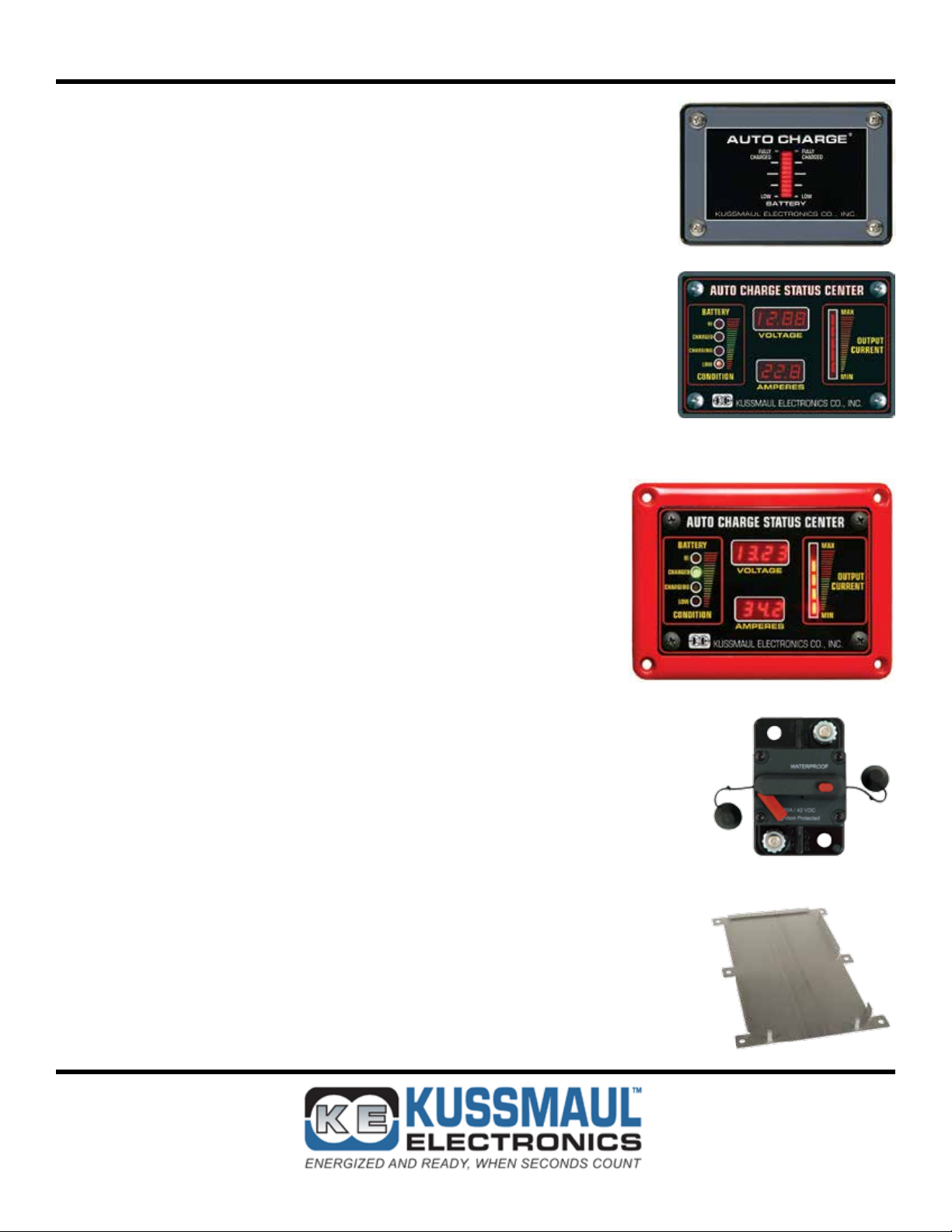
I. BAR GRAPH DISPLAY, MODEL #: 091-200-IND
• 10-Segment LED display indicate the “state of charge”
and the general condition of the batteries
II. DELUXE STATUS CENTER, MODEL #: 091-194-IND
• Indicator has a digital voltage and ampere display
• 5 segment bar graph display indicates output current
• 4 LED’s to show the condition of the batteries
III. WATERTIGHT DELUXE STATUS CENTER, MODEL #: 091-194-IND-WT-XX
• Indicator has digital voltage and ampere display
• 5 segment bar graph display indicates output current
• 4 LED’s to show the condition of the batteries
• Indicator is housed in a watertight bezel
• Bezel is available in 6 different colors,
Red, White, Blue, Yellow, Gray, and Black
Specify color choice when ordering
IV. 50 AMP WATERPROOF CIRCUIT BREAKER, MODEL #: 090-0050-0
• Combines switching and circuit breaker function
• Compact size and surface mount conguration
• Protects high amperage circuits
• Latch arms resets breaker after overload
• Cannot be held in ON position if short remains on circuit
• Waterproof - Ideal for truck applications
V. E-Z SLIDE MOUNTING PLATE, MODEL #: 091-200-EZM
• Locking mounting system
• Ease the installation and the removal of larger sized chargers
that are in harder to access areas, such as under seats
170 Cherry Avenue
West Sayville, NY 11796
www.kussmaul.com
Ph: 800-346-0857
Fax: 631-567-5826
sales@kussmaul.com
9
Page 10

INSTALLATION RECORD
DATE INSTALLED _______________________________________________________
INSTALLED BY _________________________________________________________
VEHICLE IDENTIFICATION _______________________________________________
VEHICLE OWNER _______________________________________________________
WARRANTY POLICY
All products of Kussmaul Electronics Company Inc. are warranted to be free of
defects of material or workmanship. Liability is limited to repairing or replacing
at our factory, without charge, any material or defects which become apparent in
normal use within 3 years from the date the equipment was shipped. Equipment
is to be returned, shipping charges prepaid and will be returned, after repair,
shipping charges paid.
Kussmaul Electronics Company, Inc. shall have no liability for damages of any
kind to associated equipment arising from the installation and/or use of the Kussmaul Electronics Company, Inc. products. The purchaser, by the acceptance of
the equipment, assumes all liability for any damages which may result from its
installation, use or misuse, by the purchaser, his or its employees or others.
170 Cherry Avenue
West Sayville, NY 11796
www.kussmaul.com
Ph: 800-346-0857
Fax: 631-567-5826
sales@kussmaul.com
10
 Loading...