

Page 1
INSTRUCTION MANUAL
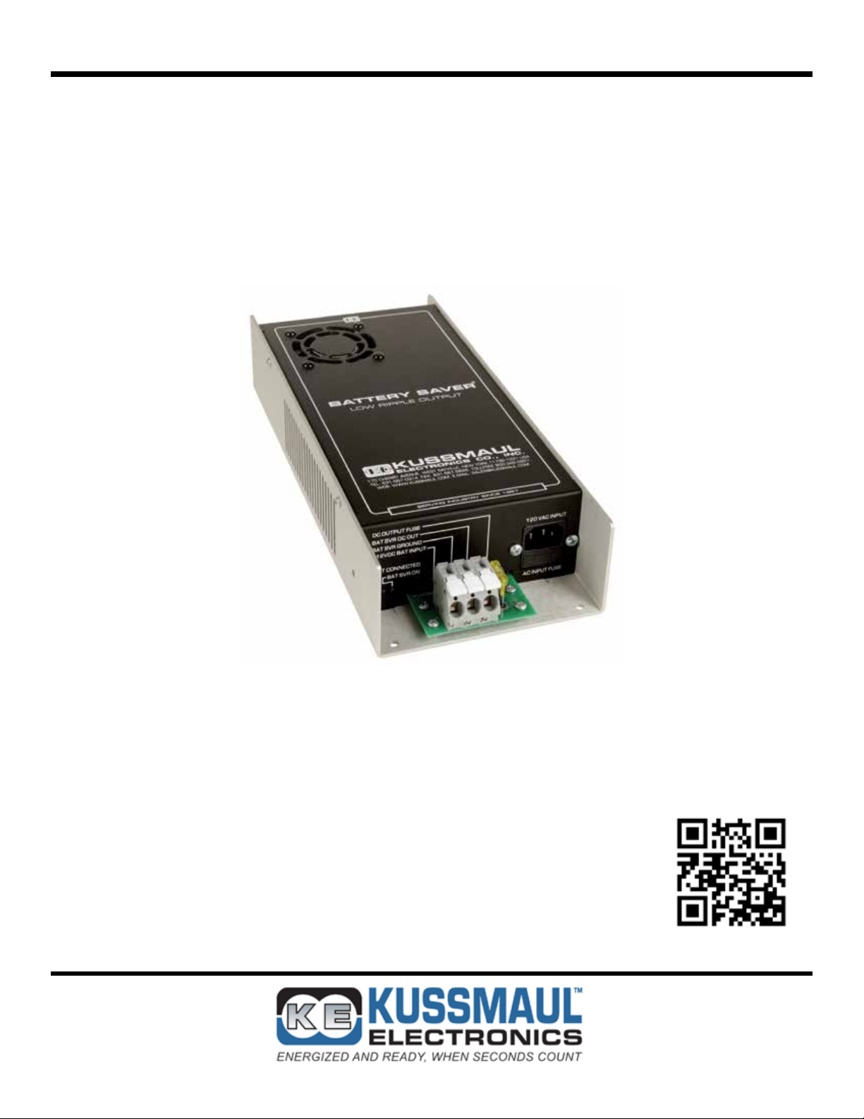
BATTERY SAVER
LOW RIPPLE HO
LOW RIPPLE POWER SUPPLY / AUTOMATIC LOAD SWITCH
FOR 12VDC VEHICLE SYSTEMS
File: IM_091-195-12_revd.indd
Rev: D
Revised By: MFG
Date: 10-23-2013
170 Cherry Avenue
West Sayville, NY 11796
www.kussmaul.com
MODEL #: 091-195-12
INPUT: 120 Volt, 50/60 Hz, 4.5 Amps RMS
OUTPUT: 13.2 Volts DC, 20 Amps
3 YEAR WARRANTY
scan using your mobile
device for more information
Ph: 800-346-0857
Fax: 631-567-5826
sales@kussmaul.com
Page 2

IMPORTANT SAFETY INSTRUCTIONS
I. PERSONAL PRECAUTIONS:
1. Someone should be within range of your voice or close enough to come to your aid when you work near
a lead-acid battery.
2. Have plenty of fresh water and soap nearby in case battery acid contacts skin, clothing, or eyes.
3. Wear complete eye and clothing protection. Avoid touching your eyes while working near a battery.
4. If battery acid contacts skin or clothing, wash immediately with soap and water. If battery acid enters
the eye, immediately ood eye with cold running water for at least 10 minutes and get medical attention
immediately.
5. NEVER smoke or allow a spark or ame in the vicinity of the battery or engine.
6. Be extra cautious to reduce the risk of dropping a metal tool onto the battery. It might spark or short-circuit
the battery or other electrical part and cause a re or an explosion.
7. Remove personal metal items such as rings, bracelets, necklaces, and watches when working with a
lead-acid battery. A lead-acid battery, when shorted, can produce a current sufcient to weld a ring or the
like metal causing a severe burn.
8. Use the battery charger for charging gel-cell, AGM and ooded lead-acid batteries only. Do not use the
charger for charging dry-cell batteries that are commonly used with home applications. These batteries
may burst and cause injury to persons and damage to property.
9. WARNING – RISK OF EXPLOSIVE GASES: Working in the vicinity of a lead-acid battery is dangerous.
Batteries generate explosive gases during normal battery operation.
II. CHARGER PRECAUTIONS:
1. NEVER charge a frozen battery.
2. Make sure the cord is located so that it will not be stepped on, tripped over, or otherwise subjected to
damage or stress.
3. Do not operate the charger with a damaged cord or plug; replace them immediately.
4. Do not operate the charger if it has received a sharp blow, been dropped, or otherwise damaged.
5. Do not disassemble the charger. Incorrect reassembly may result in a risk of electric shock and re.
6. To reduce the risk of electric shock, disconnect the charger from the AC source before attempting any
maintenance or cleaning.
7. LOCATION OF CHARGER: The charger should be mounted on a wall, vehicle oor, ventilated compartment or other suitable surface as close to the batteries to be charged as possible. Do not block the charger’s fan or air intakes. Do not mount the charger directly over the batteries as fumes may cause exces-
sive corrosion. The area should be well ventilated and free from excessive moisture, exhaust manifolds,
and battery fumes. For maximum performance, the charger should not be located in an area of extreme
high temperature. The charger is not waterproof. Do not mount the charger where there is a possibility of
water entering the unit. Evidence of water entry into the charger will void the warranty.
8. CAUTION: Do not attempt to increase battery bank capacity by splitting the output of one of the banks
with a diode-type battery isolator. The diode isolator lowers the charger voltage and results in undercharging the batteries connected to it. If additional capacity is required it is preferable to add another
isolated or parallel battery.
III. GROUND AND AC POWER CORD CONNECTION:
1. The charger should be grounded via the AC power connection to reduce the risk of electrical shock.
2. The charger must be plugged into or wired to an outlet that is an over-current protected 3 prong outlet.
Alternatively, it may be routed through a separate dedicated fuse or circuit breaker on an AC distribution
panel with proper earth/safety ground. All wiring shall comply with UL recommendations, NEC or NFPA
standards and local ordinances. Never alter the AC cord or plug if provided. Any modication of the cord
must only be done by a qualied electrician. Improper cord/outlet connection may result in a risk of elec-
trical shock.
3. Observe color coding of the AC wiring as follows:
Black………....................... AC Hot or LINE (fused)
White…………................... AC Neutral
Green…….................…….. AC Ground (safety/earth)
4. CAUTION: (230 VAC applications only): If AC input is provide from a source consisting of two HOT or
LINE leads (phase-to-phase 230 VAC input voltage); an external fuse or circuit breaker must be used to
protect both hot leads.
170 Cherry Avenue
West Sayville, NY 11796
www.kussmaul.com
Ph: 800-346-0857
Fax: 631-567-5826
sales@kussmaul.com
2
Page 3

INTRODUCTION
The Battery Saver Low Ripple (BSLR) is a power supply with a load power transfer function. Loads
connected to the BSLR are powered by the vehicle’s battery when the AC power to the BSLR is OFF.
When AC power is applied to the BSLR special circuitry within the Battery Saver transfers the load(s) to
the Battery Saver output. The Battery Saver output then provides low ripple 12VDC System power to
Battery Saver load(s). Installation of a Battery Saver eliminates the power drain on a vehicle battery and
or a battery under-charge ensuring all vehicle battery charger power is available to charge the battery.
This Battery Saver is unique in that there is no interruption of power supplied to the loads during power
transfers. The feature makes the BSLR ideal for Mobile Data Terminal (MDT) and or 12VDC vehicle
computer systems that may “re-boot” during an input power interruption.
FEATURES
I. BATTERY SAVER LOW RIPPLE
• Clean, low ripple output causes no interference with sensitive electronics
• Relay removes auxiliary loads from vehicle battery and connects to battery saver, preventing
battery discharge when in station
• Fast acting relay ensures “glitch” free power transfer
• Current limiting prevents overload
• Power “ON” LED status indicator
• Pump output with AC or DC mode rocker switch
II. LED STATUS INDICATORS
1. BATTERY CONNECTED: Indicates that a battery of proper polarity is connected to the charger
output terminals
2. BATTERY SAVER ON LED: Indicates that Battery Saver is receiving AC power and the power
supply internal to the Battery Saver is ON.
INSTALLATION INSTRUCTIONS
I. WIRING AND MOUNTING THE BATTERY SAVER LOW RIPPLE HO
1. Mount the Battery Saver in a convenient location with 4 screws in the mounting holes provided.
Be certain that adequate ventilation is available and the unit is not subject to weather damage.
2. Connect the 120VAC input power to the Battery Saver using the suppled IEC line cord as shown
in INSTALLATION WIRING DIAGRAM, See Figure 1.
3. The low voltage connections are made through the DC output connector as shown in INSTALLATION WIRING DIAGRAM, See Figure 1.
4. Connect terminal 1 to the vehicle’s 12 volt battery (+).
5. Connect terminal 2 to the vehicle ground or to the battery (-).
6. Connect terminal 3 to the +12 volt electrical loads.
7. The installation is now complete. Loads connected to the Battery Saver will be powered from
the vehicle battery when the AC power to the Battery Saver is OFF and from the Battery Saver
output when the AC power is ON.
170 Cherry Avenue
West Sayville, NY 11796
www.kussmaul.com
Ph: 800-346-0857
Fax: 631-567-5826
sales@kussmaul.com
3
Page 4

II. PRECAUTIONS
1. The Battery Saver Low Ripple HO is AC Input AND DC Output over-current protected as follows:
A. 120VAC 60Hz Input Fuse: 6.3 Amp
B. DC Output: ATC, 25 Amp
Note: The external ATC 20 Amp DC OUTPUT FUSE is common to both the Battery Saver output
AND the vehicle battery connection that supplies power to the load when the Battery Saver is
OFF (120VAC to Battery Saver - OFF).
2. OVERLOADING the Battery Saver in excess of 20 amperes when the BSLR is ON:
A. In excess of 20 amperes: initiate current limiting of the Battery Saver output with a corresponding reduction in output voltage.
B. In excess of 30 amperes: causes the ATC 25 Amp DC OUTPUT FUSE to open within 2 minutes.
3. OVERLOADING the Battery Saver in excess of 20 amperes when the BSLR is OFF:
A. When the BSLR is OFF, loads are powered by the battery, which is overload protected with
an ATC 25 Amp fuse. The fuse will open when the current exceeds 30 amperes for 2 minutes
Example:
A load of 25 amperes will cause the Batery Saver output to current limit with a corresponding
decrease of output terminal voltage to less than 10.0 VDC. This same 25 ampere load WILL NOT
cause the ATC 25 Amp fuse to immediately open when the load is connected to the vehicle battery via the BSLR.
Manage Battery Saver Connected Loads to 20 Amperes or Less!
TEST AND OPERATION
I. ELECTRICAL TEST
1. Remove AC power from the BSLR.
2. Verify “BAT SVR ON” LED is OFFand loads are being powered by vehicle battery (voltage at load
is approximately equal to vehicle battery terminal voltage).
3. Apply AC power to BSLR and verify:
A. “BAT CONNECTED” remains illuminated.
B. “ BAT SVR ON” LED illuminates approximately five (5) seconds after application of AC power
to Battery Saver.
C. Load voltage is between 13.2 VDC and 14.0 VDC.
II. OPERATION
The Battery Saver Low Ripple eliminates power delivery “glitches” or interruptions during load power
transfer(s) from: Vehicle Battery to Battery Saver: Five (5) second delay as Battery Saver output stabilizes. Installation Test para. 3.2. Battery Saver to Vehicle Battery: No delay. The MINIMUM voltage
at the load during any power transition is: Vehicle Battery VDC - 1.3VDC for a MAXIMUM of 150
milli-seconds (0.150 seconds).
170 Cherry Avenue
West Sayville, NY 11796
www.kussmaul.com
Ph: 800-346-0857
Fax: 631-567-5826
sales@kussmaul.com
4
Page 5

WIRING
Length of Wire to Battery (feet)
COM
BS OUT
VBAT IN
VBAT IN
COM
BS OUT
0 - 5
< 5 - 10
< 10 - 20*
* Consult factory if length of wire to battery is longer than 20 feet
I. BATTERY SAVER LOW RIPPLE HO WIRING INSTRUCTIONS
1. Refer to Installation Wiring Diagram I. and II.
2. Refer to Wiring Specications to determine the recommended wire size and maximum lengths.
Using a smaller gauge may cause overheating of the terminal. Additional information is available
upon request if longer, larger wiring is required.
3. Double check all wiring before applying AC power to input terminal.
4. Apply AC power (shoreline power) to input terminal and observe that the charger is operating.
5. Verify that the battery voltage appears at the charger output terminals. A minimum of 6 volts is
required to start the charger.
II. WIRING SPECIFICATIONS
Battery Charger Connections
COM
VBAT IN
BS OUT
Wire # Gauge (awg) 12 12 12 12 12 12 10 10 10
170 Cherry Avenue
West Sayville, NY 11796
www.kussmaul.com
sales@kussmaul.com
Ph: 800-346-0857
Fax: 631-567-5826
5
Page 6
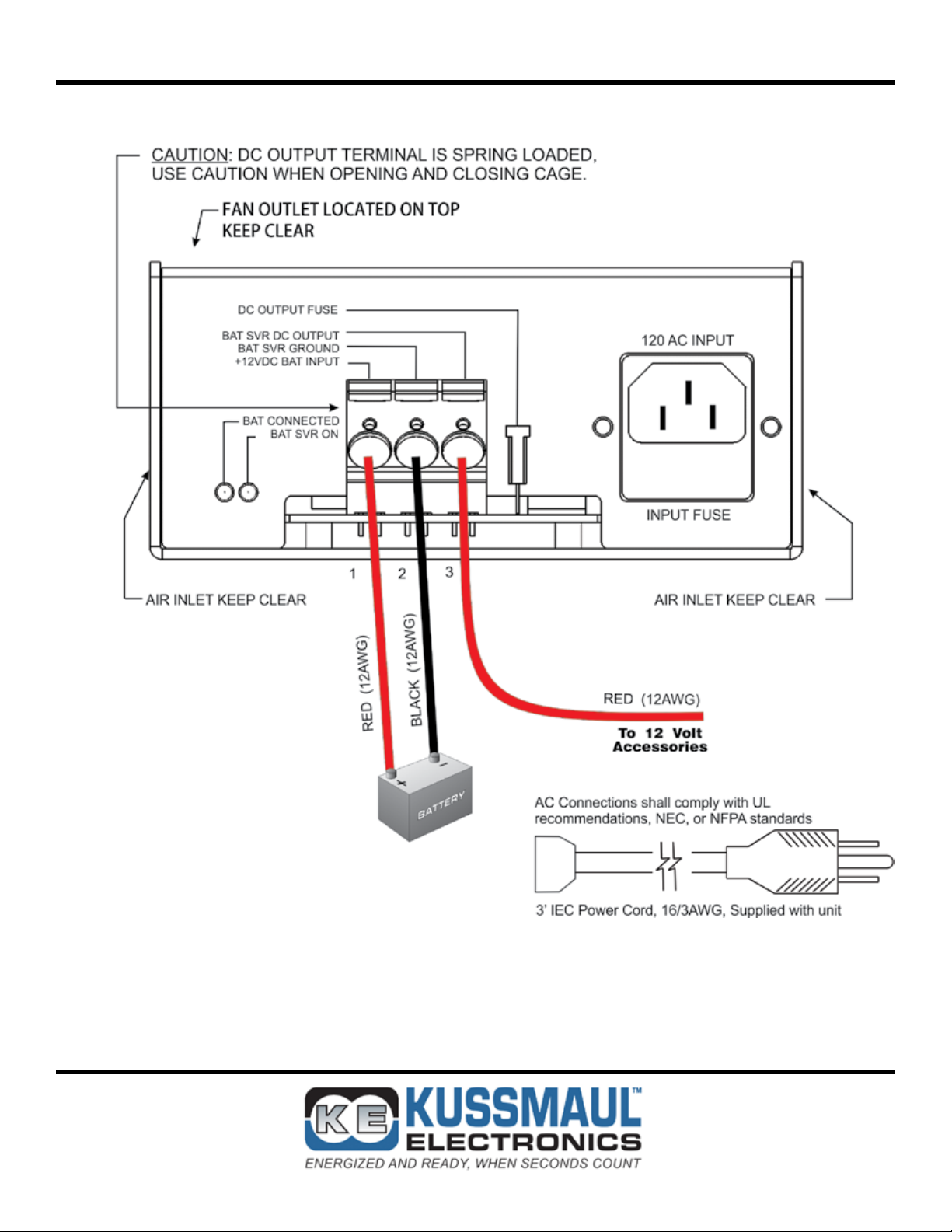
INSTALLATION WIRING DIAGRAM
I. WIRING DIAGRAM SHOWN IS FOR A 10 FOOT INSTALLATION
170 Cherry Avenue
West Sayville, NY 11796
www.kussmaul.com
Ph: 800-346-0857
Fax: 631-567-5826
sales@kussmaul.com
6
Page 7

SPECIFICATIONS
Input Power: 120 Volt, 50/60 Hz, 4.5 Amperes RMS
Input Fuse: (2) - 6.3 Amp, fast acting, 5 X 20mm
Output Power: 13.2 Volts DC, 20 Amperes Max
Output Ripple: 30 millivolts, AC., RMS
Output Fuse: 25 Amp, fast acting Autofuse, Please refer to Installation Precautions
Electronic Current Limit: 20 Amps D.C. from Battery Saver output, Please refer to Installation Precautions
LED Status Indicators: Battery Connected: Green LED, Battery Saver ON: Green LED
Weight: 4 pounds
OUTLINE DRAWING
5.50
12.4
FAN
OUTLET
13.00
4.50
0.187" DIA. 4 HOLES
2.50
170 Cherry Avenue
West Sayville, NY 11796
www.kussmaul.com
Ph: 800-346-0857
Fax: 631-567-5826
sales@kussmaul.com
7
Page 8

INSTALLATION RECORD
DATE INSTALLED _______________________________________________________
INSTALLED BY _________________________________________________________
VEHICLE IDENTIFICATION _______________________________________________
VEHICLE OWNER _______________________________________________________
WARRANTY POLICY
All products of Kussmaul Electronics Company Inc. are warranted to be free of
defects of material or workmanship. Liability is limited to repairing or replacing
at our factory, without charge, any material or defects which become apparent in
normal use within 3 years from the date the equipment was shipped. Equipment
is to be returned, shipping charges prepaid and will be returned, after repair,
shipping charges paid.
Kussmaul Electronics Company, Inc. shall have no liability for damages of any
kind to associated equipment arising from the installation and/or use of the Kussmaul Electronics Company, Inc. products. The purchaser, by the acceptance of
the equipment, assumes all liability for any damages which may result from its
installation, use or misuse, by the purchaser, his or its employees or others.
170 Cherry Avenue
West Sayville, NY 11796
www.kussmaul.com
Ph: 800-346-0857
Fax: 631-567-5826
sales@kussmaul.com
8
 Loading...