

Page 1

File: 091-165-12-DV rev b.P7.0
Rev: B, Date: 3-31-10
INSTRUCTION MANUAL
AUTO CHARGE 12 DV
AUTOMATIC BATTERY CHARGER
MODEL #091-165-12-DV
INPUT: 115 or 230VAC, 50/60Hz
OUTPUT: 13.2VDC (nom.), 12 Amperes
NOTE :
This charger is designed for
vehicles with a single
battery system
3 YEAR WARRANTY
KUSSMAUL ELECTRONICS CO., INC.
170 CHERRY AVE., WEST SAYVILLE, N.Y. 11796-1221
Phone: 631-567-0314 Toll Free: 800-346-0857 Fax: 631-567-5826
Web: www.kussmaul.com E-Mail: sales@kussmaul.com
Page 2

INTRODUCTION
This manual describes the installation and wiring for the Auto-Charge 12DV Automatic Battery
Charger. It is suggested that the installer read the entire instruction manual to become familiar
with the tasks involved before operating the charger.
INSTALLATION
The installation of the vehicle wiring must provide a direct connection between the battery [+,
-] terminals and the Auto-Charge 12DV, Model: 091-165-12-DV, Automatic Battery Charger.
The battery is automatically charged at constant voltage. For deeply discharged batteries or
if the charger is operated while the vehicle is started, a current limiter automatically limits the
output to 12 amperes. Input power may be either 115 VAC or 230 VAC, 50 or 60 Hz. A
recessed input voltage selector switch is provided on the charger front panel near the input
terminal strip.
The Auto-Charge 12DV uses remote sensing via the charging wires to the battery under
charge and therefore only the battery charging wires are necessary to connect to the battery
to the charger. These connections are made on the "OUTPUT" terminal strip.
Refer to FIGURE 1, Installation Wiring Diagram.
The Auto-Charge 12DV Automatic Battery Charger should be installed in an area with
adequate ventilation. A switch on the front panel of the charger selects either "115V" or "230V"
VAC. Set this switch to the proper position to correspond to the input voltage before applying
power to the charger.
1. Mount the charger using the four holes provided. Refer to "OUTLINE DRAWING,
FIGURE 2.
2. Connect the wiring from the batteries to the Output Terminal Strip. Spade lugs that
have been securely crimped or soldered should be used.
3. Connect the wiring to the batteries. Ring lugs that have been securely crimped or
soldered should be used.
4. Double check all wiring before proceeding.
5. Wire the VAC input power line to the power source and check the position of the
Voltage Selector Switch.
6. The pilot light will light to show that the charger has power.
7. The ammeter will indicate how much current is flowing to the battery. A charging
current limit of 12 amperes is factory set.
*************IMPORTANT SAFETY INSTRUCTIONS*************
DO NOT APPLY 230 VOLTS TO THE CHARGER WITH
115/230VAC SELECTOR SWITCH IN THE 115 VOLT POSITION
SERIOUS DAMAGE WILL RESULT
Page 3
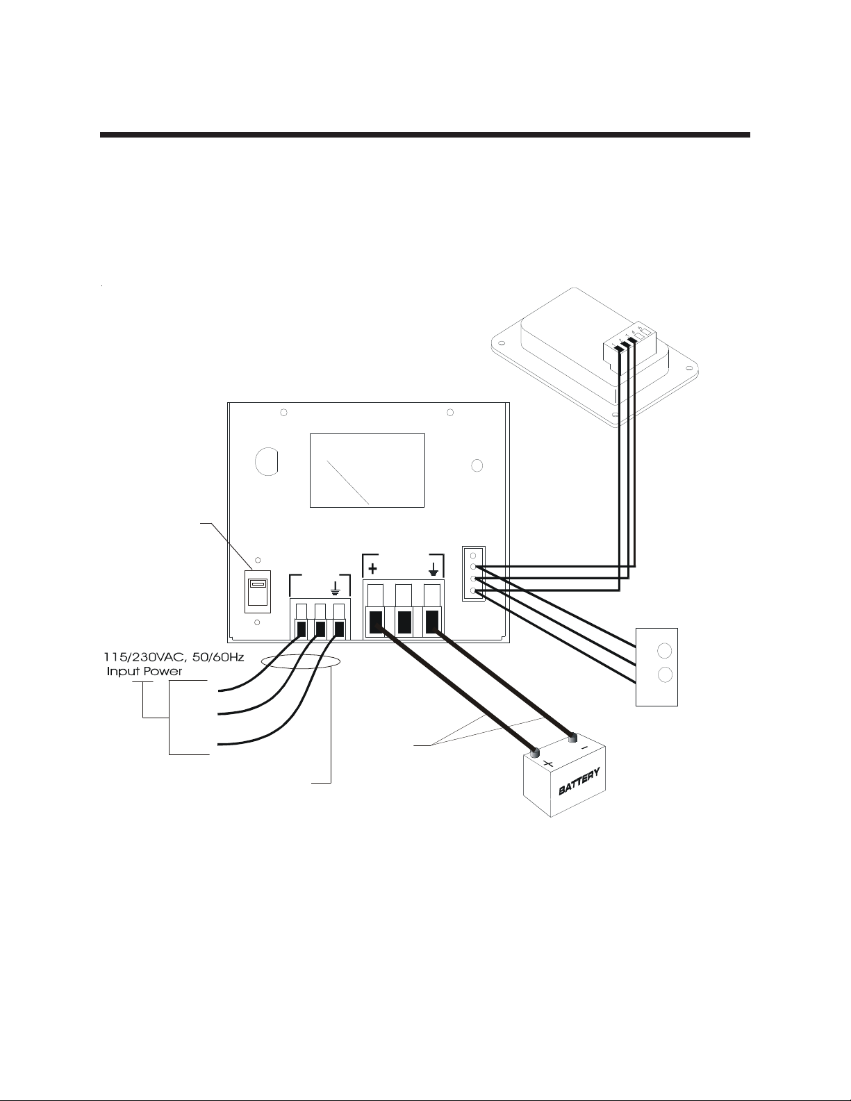
INSTALLATION WIRING DIAGRAM
FIGURE 1
Optional Bar-graph
Indicator
091-165-016
5AMP
POWER
FUSE
115/230VAC
SELECTOR SWITCH
115VAC SHOWN
Note 3.
OUTPUT
INPUT
115V
LN
REMOTE
W
K
Optional Economy
Indicator
Y
E
L
L
O
B
L
A
C
R
E
D
Line
Neutral
Ground
AWG 16 X 3
TYPE SJ
NOTE 1
AWG 1 4
NOTE 1, 2
091-90-012-12
Notes:
1. 115/230VAC Input Power and Charger Output Power strain relief cover not shown
for clarity. Refer to INSTALLATION "Important Safety Instructions" section of this
manual.
2. Charger output power connections, AWG 14, for 20 feet Maximum. Consult factory
if longer length is required.
3. 115VAC operation shown. For 230VAC toggle voltage select switch down so that
"230V" is clearly shown in window of selector switch.
Page 4

SPECIFICATION & OUTLINE
SPECIFICATIONS:
Input: 115/230VAC, 50/60 Hz, 3/1.5 Amps
Input Fuse: 5 Amps, CAUTION: DISCONNECT SUPPLY BEFORE CHANGING FUSE
Output: 13.2VDC, nominal
Output Fuse (Optional): 24 Amps
Output Current: 12 Amps
Charge Indicator: 0-15 amps +/-5%
Weight: 10 lbs
FIGURE 2
9/32" D IA.
4.375
5.50
10.375
OUTLINE DRAWING
11.375
4.375
Page 5
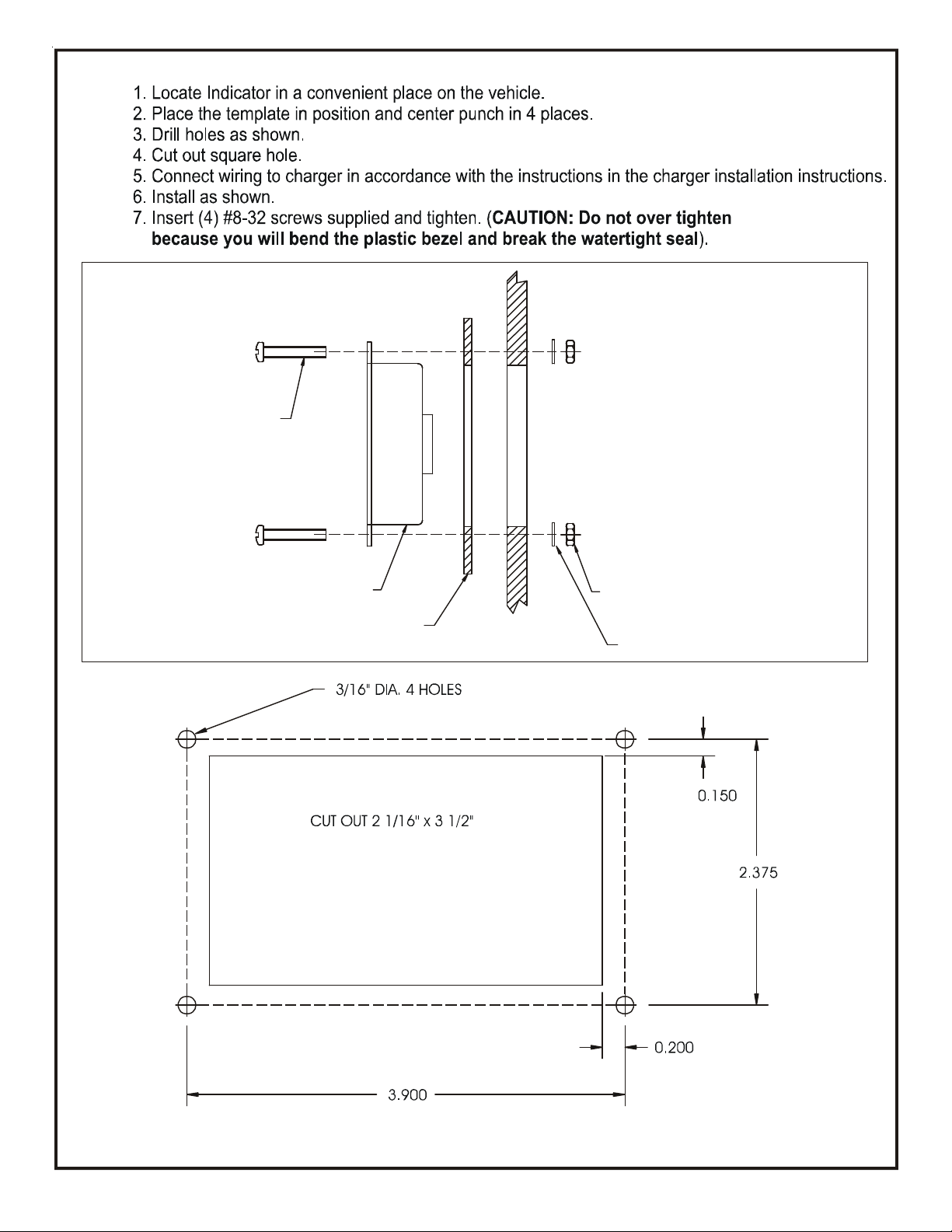
8-32 SCREW
INDICATOR INSTALLATION
INDICATOR
GASKET
HOLE TEMPLATE
#8-32 HEX NUT
TRUCK WALL
LOCK & FLAT WA SHER
Hole Template may not be to Scale, please check dimensions before using.
File: Ind.cdr rev C: 3-31-10 do not shrink this art wo rk
Page 6

INSTALLATION RECORD & WARRANTY
Date Installed
Installed By
Vehicle Identification
Vehicle Owner
WARRANTY
All product of Kussmaul Electronics Company Inc. are warranted to be free
of defects of material or workmanship. Liability is limited to repairing or
replacing at our factory, without charge, any material or defects which
become apparent in normal use within 3 years from the date the equipment
was shipped.
Kussmaul Electronics Company, Inc. shall have no liability for damages of
any kind to associated equipment arising from the installation and /or use of
the Kussmaul Electronics Company, Inc. products. The purchaser, by the
acceptance of the equipment, assumes all liability for any damages which
may result from its installation, use or misuse, by the purchaser, his or its
employees or others.
 Loading...