

Page 1

File: 091-149 rev b.pmd
Rev: B, Date: 4-1-10
INSTRUCTION MANUAL
AUTO CHARGE 75-BG
AUTOMATIC BATTERY CHARGER
MODEL #091-149-XX-XXX
NOTE:
THIS CHARGER IS DESIGNED
FOR A SINGLE BATTERY SYSTEM.
3 YEAR WARRANTY
KUSSMAUL ELECTRONICS CO., INC.
170 CHERRY AVE., WEST SAYVILLE, N.Y. 11796
Phone: 631-567-0314 Toll Free: 800-346-0857 Fax: 631-567-5826
Web: www.kussmaul.com E-Mail: sales@kussmaul.com
Page 2

TABLE OF CONTENTS
Introduction
Installation
Specification & Outline
Warranty
LIST OF ILLUSTRATIONS
Figure 1 Block Diagram
Figure 2 Electrical Arrangement
Figure 3 Wiring
Page 3

INTRODUCTION
The Auto Charge 75-BG, Model 091-149 is a compact, high output, completely automatic
battery charger. Available in a wide array of output voltages, it may be specified for operation
from either 120 volts or 230 volts, 50/60 Hz. The specification chart lists the various models
with the output current ratings.
Battery Charger Features:
* Electronic remote sensing of true battery voltage, eliminates the need for remote
sensing wires
* Automatic current limiting
* Battery charge/condition indicator, bottom bar indicates power "ON"
* 0-100 ampere panel meter to indicate charger output current
* A controlled fan operates when the current exceeds 30 amperes and keeps the
charger components cooled.
The charger functions automatically by adjusting its output voltage by varying the triggering
angle of the silicon controlled rectifiers of the full wave rectifier. Output current is detected by
sensing the voltage across a low resistance shunt and modifying the triggering angle to limit the
current. A block diagram appears in figure 1.
Automatic remote sensing measures the true battery voltage, eliminating the need for additional
sensing wires. The output current of the charger is inherently a series of pulses whose frequency
is determined by the power line frequency. Therefore there are brief intervals when no charging
current flows. During this brief interval the battery charger measures and stores the battery voltage. The measured voltage is compared to a reference and any error detected is used to control
the charger output.
This charger may remain energized and connected to the battery for extended periods of time
with no danger of overcharging or water boil-off.
Page 4

INSTALLATION
The Auto Charge 75 – BG automatic battery charger should be installed in an area with adequate
ventilation. A power cord and output wires are provided. A 3 foot extension for the remote bar
graph is included. These 3 wires may be extended using butt splices if a longer distance is
required.
Mount the charger using the four holes provided. See the outline and mounting drawings.
1. Connect the red wire to the battery positive, and the black wire to the battery negative. Be
certain that the battery voltage corresponds to the output voltage rating of the charger.
2. Connect the bar graph cable as shown in the installation diagram.
3. Double check all wiring before proceeding.
4. Wire the A.C. power line to a power source that corresponds to the input requirements of
the charger.
Page 5

INPUT
POWER
ISOLATION
TRANSFORMER
POWER
SUPPLY
COSINE
RAMP
GENERATOR
12 VOLT
REGULATED
+12V
REF. INPUT
VOLTS
ADJUST
AMPLIFIER
VOLTAGE
SENSE FROM
CHARGER OUTPUT
AMPS
ADJUST
S/H
AMPLFIER
AMPLIFIER
CURRENT LIMIT FEEDBACK
COMPARATOR
G1
POWER
AMPLIFIER
K
TRIGGER
TRANSFORMER
G2
CURRENT
SENSE
THRESHOLD
CURRENT
LIMIT
AMPLIFIER
Figure 1
BLOCK DIAGRAM, AUTO CHARGE CONTROL CIRCUIT
Page 6

FAN
A
INPUT
POWER
POWER
INPUT
POWER
TRANSFORMER
KG1G2
CONTROL P.C. BOARD
G1
G2
CURRENT
SENSE
MMETER
K
CHARGER
OUTPUT
VOLT
SENSE
Figure 2
Model 091-149, Auto Charge, Electrical Arrangement
Page 7

CABLES & CONNECTOR
SUPPLIED WITH
CHARGER
091-39-022
REMOTE BAR GRAPH DISPLAY
RED
WHITE
BLACK
Y
E
L
L
O
W
BLACK
RED
.
G
E
N
,
K
C
A
L
B
,
G
W
A
4
#
W
A
4
#
P
D
E
R
,
G
.
S
O
FIGURE 3
INSTALLATION WIRING
Green
GROUND
W
h
i
t
e
B
l
a
c
k
NEUTRAL
A.C. POWER INPUT
LINE
Page 8
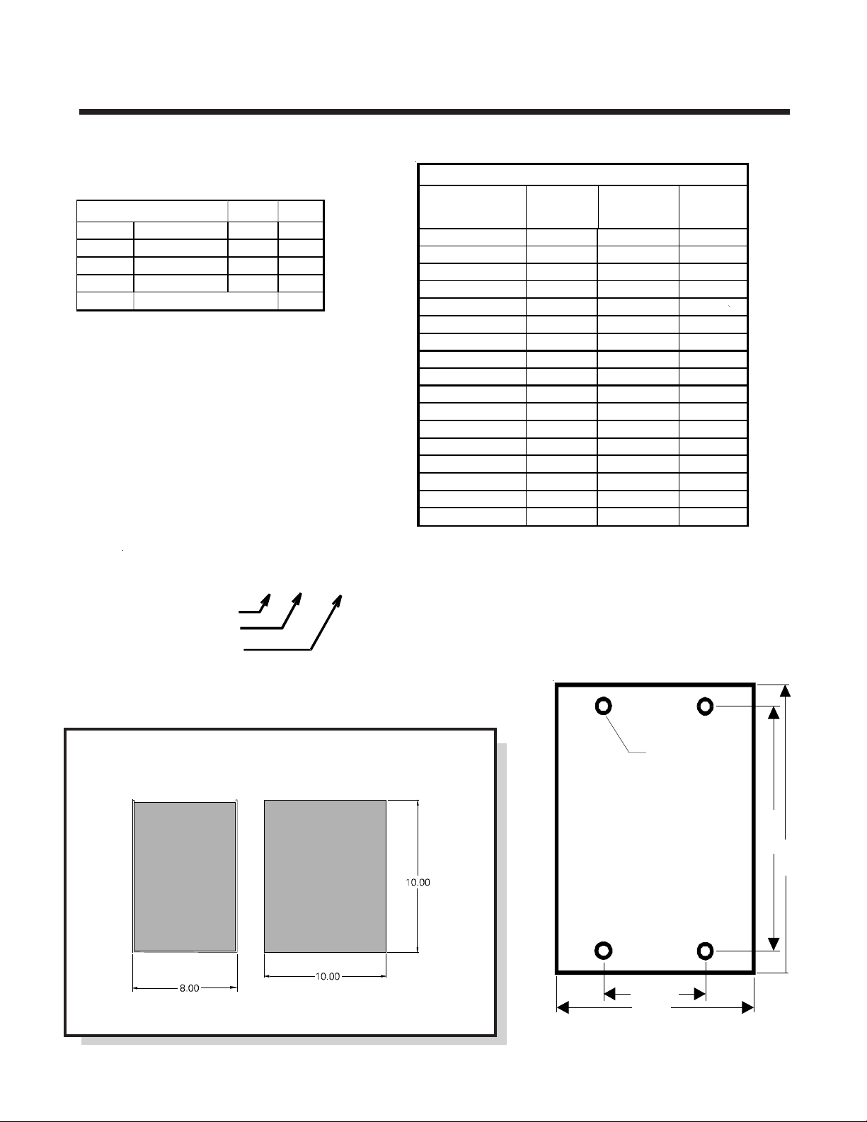
SPECIFICATION & OUTLINE
SPECIFICATIONS:
INP U T:
VOLTS FREQUENCY AMPS FUSE
120 50/60 Hz 17 20
230 50/60 Hz 9 12
277 50/60 Hz 8 10
all fuses are slo-blo
Output: see chart
Output Current: see chart
Weight: 65 lbs
Model Number Specification
SPECIFICATION CHART
MODEL # INPUT OUTPUT OUTPUT
VOLTAGE VOLTAGE AMPS
091-149-12 120 A.C. 12 D.C. 75
091-149-24 120 A.C. 24 D.C. 40
091-149-32 120 A.C. 32 D.C. 30
091-149-36 120 A.C. 36 D.C. 27
091-149-48 120 A.C. 48 D.C. 25
091-149-72 120 A.C. 72 D.C. 15
091-149-96 120 A.C. 96 D.C. 12
091-149-120 120 A.C. 120 D.C. 10
091-149-12-230 230 A.C. 12 D.C. 75
091-149-24-230 230 A.C. 24 D.C. 40
091-149-32-230 230 A.C. 32 D.C. 30
091-149-36-230 230 A.C. 36 D.C. 27
091-149-48-230 230 A.C. 48 D.C. 25
091-149-72-230 230 A.C. 72 D.C. 15
091-149-96-230 230 A.C. 96 D.C. 12
091-149-120-230
091-149-48-277 277 A.C. 48 D.C. 25
230 A.C. 120 D.C. 10
091-149-XX-XXX
Basic Model
D.C. Output Volts
A.C. Input Volts
(Only specify if
other than 120V)
4 HOLES,TYP.
7/16 DIA.
CHARGER HAS
3/8-16 THREADED
8.50
INSERTS
10.0
4.375
OUTLINE DRAWING
MOUNTING
8.0
Page 9

8-32 SCREW
INDICATOR INSTALLATION
INDICATOR
GASKET
HOLE TEMPLATE
#8-32 HEX NUT
TRUCK WALL
LOCK & FLAT WA SHER
Hole Template may not be to Scale, please check dimensions before using.
File: Ind.cdr rev C: 3-31-10 do not shrink this a rt work
Page 10

INSTALLATION RECORD & WARRANTY
Date Installed
Installed By
Vehicle Identification
Vehicle Owner
WARRANTY
All products of Kussmaul Electronics Company Inc. are warranted to be
free of defects of material or workmanship. Liability is limited to repairing or
replacing at our factory, without charge, any material or defects which
become apparent in normal use within 3 years from the date the equipment
was shipped. Equipment is to be returned, shipping charges prepaid and will
be returned, after repair, shipping charges paid.
Kussmaul Electronics Company, Inc. shall have no liability for damages
of any kind to associated equipment arising from the installation and /or use
of the Kussmaul Electronics Company, Inc. products. The purchaser, by the
acceptance of the equipment, assumes all liability for any damages which
may result from its installation, use or misuse, by the purchaser, his or its
employees or others.
 Loading...