

Page 1

FILE: IM_091-127-12E-80-115
Rev A., 04-03-07
INSTRUCTION MANUAL
®
AUTO CHARGE ODY
AUTOMATIC BATTERY CHARGER
MODEL #091-127-12E-80-115VAC
for ODYSSEY PC Series BATTERIES
13.60 to 14.70 VDC, 80 Amperes
CAUTION
This charger is calibrated to the
ODYSSEY requirement of 14.7 volts
in the bulk/absorption range and 13.6
volts in the float mode
DO NOT USE TO CHARGE A
NORMAL FLOODED LEAD ACID
BATTERY
3 YEAR WARRANTY
KUSSMAUL ELECTRONICS CO., INC.
170 CHERRY AVE., WEST SAYVILLE, N.Y. 11796
TEL: in NY 631-567-0314 TOLL FREE: 800-346-0857 FAX: 631-567-5826
Page 2

INTRODUCTION
The AUTO CHARGE, ODY Charger, Model 091-127-12E-80-115 is a completely automatic
single channel battery charger designed specifically for periodic charging of ODYSSEY PC
Series Batteries and certain types of AGM Batteries (consult factory). Of rugged
construction, the charger is made to withstand the shock and vibration encountered in
vehicle mounted equipment. Utilizing components which meet international safety
standards makes this charger ideal for worldwide applications.
BATTERY CHARGER FEATURES
Completely automatic operation, charges battery on demand
Output Voltage regulated, eliminates overcharging battery
Output Voltage, temperature compensated (optional)
Output, current limited to protect charger from overloading
A 5-LED display indicating charge state and faults
Reverse polarity protection
INSTALLATION
The AUTO CHARGE ODY Charger should be installed in an area with adequate ventilation.
Mount the charger using the four holes provided in chassis.
Connect charger wiring directly to the battery for optimum charger performance.
Double check battery wiring. Verify that the battery voltage appears at the charger output
connections. (See Figure 3).
Page 3

PRINCIPLES OF OPERATION
A three-step lead acid battery charger operates in the three stages described below:
1) A discharged battery is recharged at a constant current (bulk charge) until its voltage
reaches an overcharge level of 2.45 volts per cell. At this time the charger will switch
to Finish Charge. The battery accepts 75-85% of its capacity during bulk charge.
2) This overcharge voltage is now maintained constant at 2.45 volts per cell (absorption
or finish charge) for eight (8) hours.
3) After an eight (8) hour Finish Charge Stage has completed the charger will "Time Out"
to a Float Charge Stage wherein the battery under charge will receive a 13.6VDC Float
Charge or 2.26VDC per cell The battery is maintained at full charge during Float Charge,
and the green indicator labeled “Battery Charged” AND red indicator labeled Time Out
will be illuminated.
Figure 1 depicts the above described operation. Note that the term “absorption charge” is
used interchangeably with “finish charge”. Upon application of AC power, the charger is
placed into bulk charge if necessary. When the charger switches to finish charge, a timer
starts. This timer has a duration of eight (8) hours after which the charger will automatically
go to float charge (Battery Charged green indicator) and a time-out will be indicated.
A battery fault indicator is provided to indicate the absence of a battery, a battery connected
with reverse polarity, or a battery with an open circuit terminal voltage of less than 1.35 volts
per cell.
TEMPERATURE COMPENSATION
Temperature compensation is provided as an optional feature. A temperature probe is
provided which can be placed in the air surrounding the battery or bonded to the battery
case.
Page 4
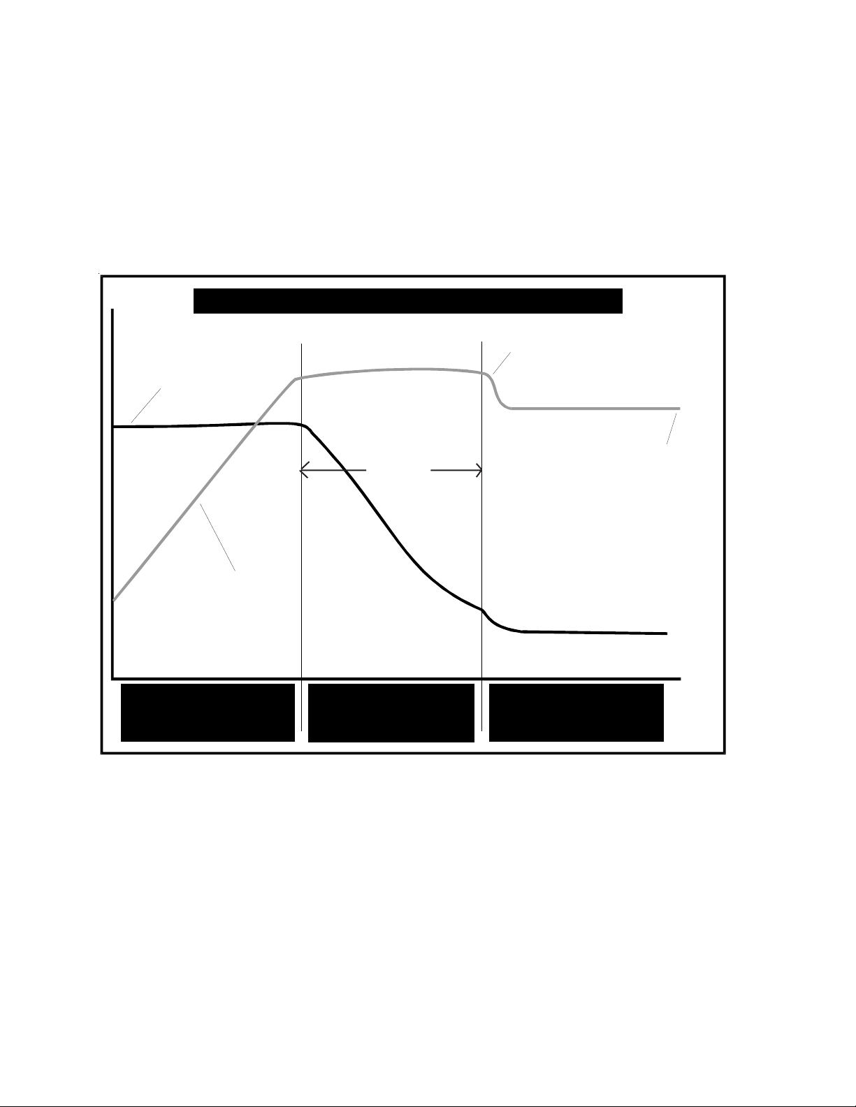
THREE STAGE CHARGING CURVE
Model: 091-127-12E-80-115
BATTERY
CURRENT
I Limit=80.0A
BATTERY
VOLTAGE
Voltage Increasing
Current Constant
STAGE I
CONSTANT CURRENT
(BULK)
14.70VDC
8.0 Hours
Voltage Constant
Current Decreasing
STAGE II
CONSTANT VOLTAGE
(ABSORPTION)
ABSORPTION STAGE
13.60VDC
FLOAT
STAGE
Voltage Constant
Full Charge Maintained
STAGE III
CONSTANT VOLTAGE
(FLOAT)
TIME
Figure 1
Page 5
NOTE: This charger is designed to have it’s output voltage compensated for changes in
Temperature. A switch on the circuit board selects whether the unit is operated in the
compensated or uncompensated mode. WHEN IN THE TEMPERATURE COMPENSATED
MODE THE THERMISTOR MUST BE CONNECTED. Operation without the thermistor
while in the compensated mode will result in loss of voltage control and overcharging
of the battery.
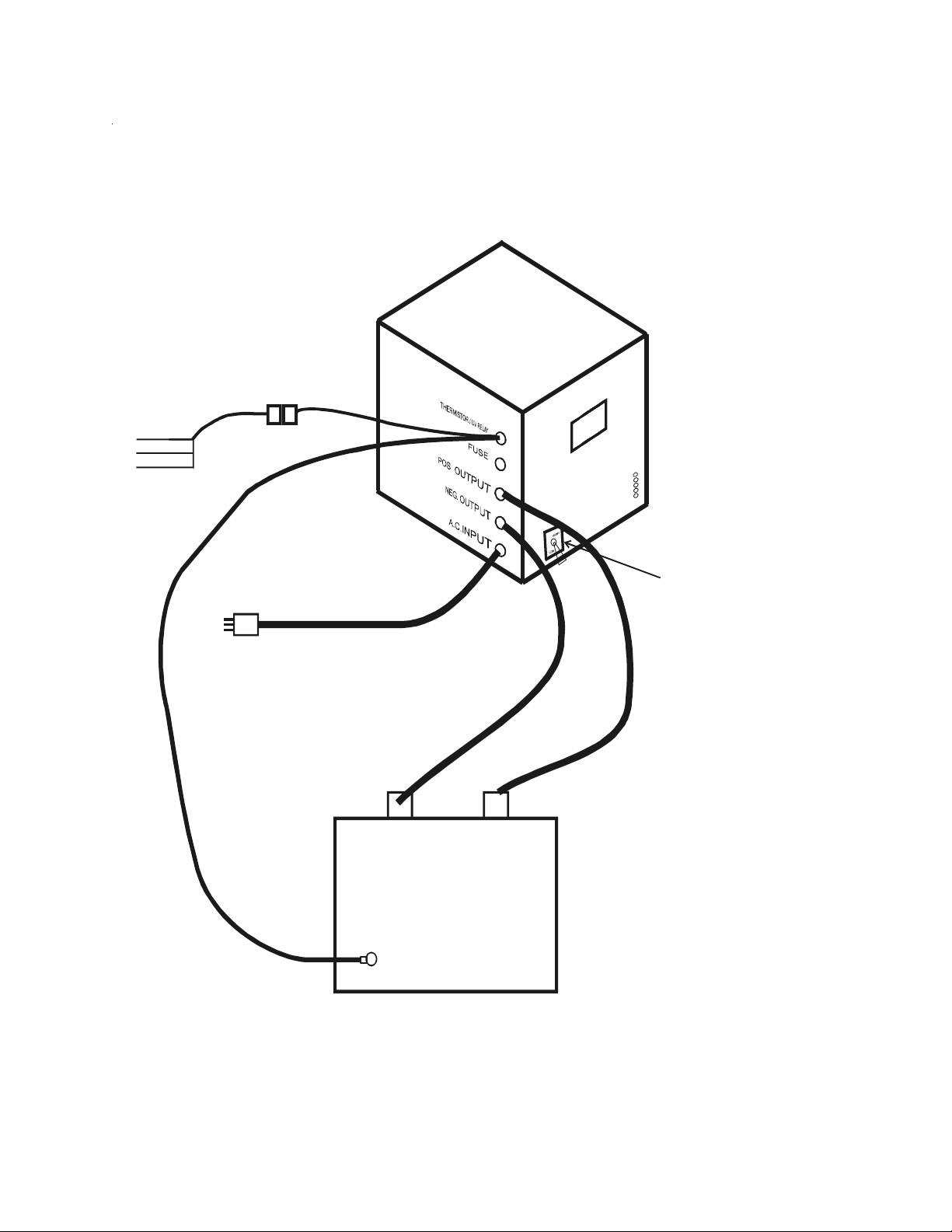
UV RELAY Customer Interface
(Optional)
White
COM
Green
NC
Black
NO
OUTPUT
CURRENT
HIGH/LOW
SWITCH
(OPTIONAL)
A.C. POWER
THERMISTOR
(OPTIONAL)
-
+
BATTERY
Figure 2
INSTALLATION WIRING
Page 6
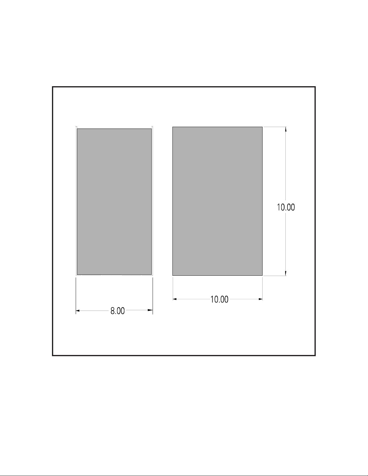
OUTLINE DRAWING
FIGURE 3
Page 7

Specifications
Model: 091-127-12E-80-115
Input Power: 120VAC, 60Hz, 16Amps, NEMA 5-20 Minimum
Input Over Current Protection: Fuse; 20Amp, Slow-Blow
Output Power: 12 to 14.7VDC, 80Amperes Current Limited
Charge Indicator: 100Amperes
Mode Indicators:
Battery Fault; Red
Time-out: Red
Bulk Charge: Yellow
Finish Charge: Yellow
Battery Charged: Green
Recommended Battery Size:
Odyssey, AGM Series "PC", 150 to 300 AH
Weight: 65 Pounds
Temperature Compensation: Optional
Under Voltage (UV) Detection: Optional
Output Current High/Low Switching: Optional
Page 8

Page 9

INSTALLATION RECORD & WARRANTY
Date Installed
Installed By
Vehicle Identification
Vehicle Owner
WARRANTY
All products of Kussmaul Electronics Company Inc. are warranted to
be free of defects of material or workmanship. Liability is limited to repairing or replacing at our factory, without charge, any material or defects
which become apparent in normal use within 3 years from the date the
equipment was shipped.
Kussmaul Electronics Company, Inc. shall have no liability for damages of any kind to associated equipment arising from the installation and
/or use of the Kussmaul Electronics Company, Inc. products. The purchaser, by the acceptance of the equipment, assumes all liability for any
damages which may result from its installation, use or misuse, by the
purchaser, his or its employes or others.
 Loading...