

Page 1
FILE: 091-84.P65 date: 06-02-99
INSTRUCTION MANUAL
ENGINE IDLER MODULE
PART OF A HIGH IDLE SYSTEM
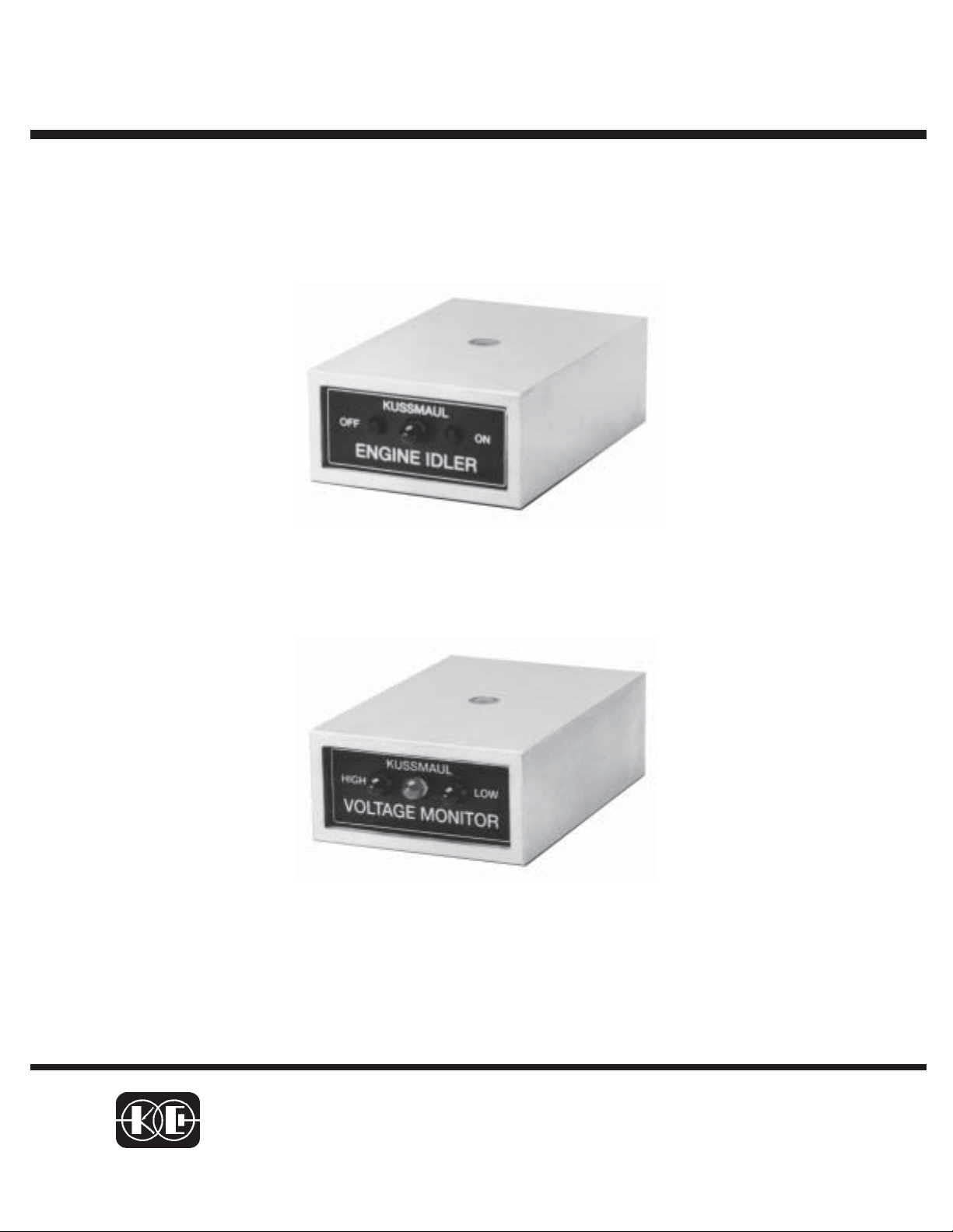
ENGINE IDLER
MODEL #091-84-005
VOLTGAE MONITOR
MODEL #091-84-004
3 YEAR WARRANTY
KUSSMAUL ELECTRONICS CO., INC.
170 CHERRY AVE., WEST SAYVILLE, N.Y. 11796
TEL: in NY 631-567-0314 TOLL FREE: 800-346-0857 FAX: 631-567-5826
Page 2

INTRODUCTION
The High Idle System consists of a model 091-84-005 Engine Idler and a model 091-84-004
Voltage Monitor. The system permits a vehicle operator to increase engine RPM to obtain
more alternator output. RPM may be increased manually from the Engine Idler or automatically from the Voltage Monitor when the system voltage drops below the threshold. In order
to move the throttle mechanism or interface with electronic controlled engines additional
components are required.
DESCRIPTION
ENGINE IDLER:
This module is the heart of the system. It interfaces with the Brake Pedal Switch, the Voltage
Monitor, Neutral Safety Switch and the output solenoid valve or relay. The Engine Idler has
a High Idle "ON" and "OFF" pushbuttons on its front face allowing the operator to switch in
and out of HIGH IDLE when the vehicle is in Park or Neutral. An LED indicator on the front
face is illuminated when the engine is in HIGH IDLE.
VOLTAGE MONITOR:
This module interfaces with the Engine Idler module to activate the high idle system
whenever the detected voltage drops. Three LED's indicate High, Low or Normal battery
voltage. When the battery voltage is above 15.6 volts D.C. the HIGH indicator is illuminated.
The LOW battery voltage indicator illuminates when the battery voltage is below 12.5 volts.
At this time a signal is sent to the Engine Idler module automatically placing it in high idle.
This occurs only if the transmission is in Park or Neutral and the brake pedal is not
depressed.
Page 3

INSTALLATION
Typical installations are illustrated in figures 1 through 4. Mount actuator and solenoid valve
in an appropriate location and connect the actuator output to the throttle mechanism. (Note:
The actuator and solenoid valve must be purchased seperately. Kits that simplify the
actuator mounting and connection are available for several engines. Consult KECO sales
Department). Be certain that the ball chain or other coupling does not restrict throttle motion
at full closed throttle or wide-open throttle. Connect solenoid valve air lines and electrical
wiring as illustrated.
OPERATION
The High Idler receives its power from the ignition switch and functions only when the
ignition switch is either "ON" or in the ACC. position. High Idle is automatically disabled
under any of the following conditions:
1. Operator depresses the "OFF" pushbutton on the Engine Idler
2. Operator depresses the brake pedal
3. Operator places the transmission into Drive or Reverse
4. Operator turns off the ignition switch
Page 4

TEST PROCEDURE
1. With the transmission switch in PARK turn the ignition switch the Accessory
position. The LED on the Engine Idler should remain OFF.
2. Press the "ON" switch on the Engine Idler. The LED on the Engine Idler should turn
ON.
3. Move the transmission to Drive or Reverse. The LED on the Engine Idler should
turn OFF.
4. Place the transmission in PARK and press the "ON" switch to turn the LED ON
again.
5. Depress the Brake Pedal. This should turn the LED OFF.
NOTE:
Steps 1 thru 5 are valid only if the battery voltage is greater than 12.5 volts. If less than
12.5 volts, the Voltage Monitor may turn on High Idle system.
6. Start the engine and allow it to warm up with the transmission in PARK mode.
7. Depress the ON switch on the Engine Idler and adjust the coupling to the actuator
and the stroke to obtain the desired engine RPM. Recheck by turning the unit ON and
OFF a few times.
8. Load the electrical system by turning on the headlights, area lights or other
accessories. Note that when the voltage drops below 12.5 volts, the following occur:
a. The Low indicator on the Voltage Monitor illuminates.
b. The indicator on the Engine Idler illuminates.
c. The High Idle System is active and the engine is speeded up.
Page 5

CAUTION
FORD INSTALLATIONS
FORD, in many installations uses a star ter
solenoid which has one side of the coil
grounded. The neutral safety switch is then
placed in the supply side of the solenoid coil.
This configuration creates a considerable
voltage spik e when the v ehicle is started.
A diode must be placed across the starter
solenoid in these installations to prevent damage to the engine idler .
See the appropriate wiring diagram for diode
installation details.
Page 6

CHAIN,
CONNECT TO
THROTTLE LINKAGE
VACUUM
ACTUATOR
BRAKE
LIGHT
091-84-VA
Stroke adjust
TO VACUUM
SOURCE
T
N
I
U
O
091-84-VV
SOLENOID
AIR VALVE
BA TTERY +
BRAKE SWITCH
NEUTRAL
SAFETY SWITCH
CLOSE IN
NEUTRAL/PAR K
1 amp fu s e
DIODE
On some vehicles install diode to
prevent emergency flasher or
turn signals from turning off the
engine idler
To +12 volts
thru accessory
position of
Ignition switch
KUSSMAUL
OFF
ON
ENGINE IDLER
ENGINE IDLER INSTALLATION
Figure 1
Page 7

V
CHAIN,
CONNECT TO
THROTTLE LINKAGE
BRAKE
LIGHT
091-84-VA
Stroke adjust
SOURCE
T
N
I
U
O
ACUUM
ACTUATOR
BRAKE SWITCH
BA TTERY +
Starter
Solenoid
Connect 1N4004
as shown to suppress
starter solenoid tr ansient
DIODE
On some vehicles install diode to
prevent emergency flasher or
turn signals from turning off the
engine idler
+12 volts from ignition switch
in "START" position
SEE NOTE:
NEUTRAL
SAFETY SWITCH
CLOSED IN NEUTRAL OR PARK
091-84-VV
SOLENOID
AIR VALVE
NOTE:
Some engines have one
side of starter solenoid at
ground and the neutral
safety switch in the supply
side.
These must have a diode
installed across the s tarter
solenoid as illustrated.
FOR ENGINES WITH NEUTRAL SAFETY SWITCH CONNECTED TO STARTER
KUSSMAUL
OFF
ON
ENGINE IDLER
ENGINE IDLER INSTALLATION
1 amp fu s e
To +12 volts
thru accessory
position of
Ignition switch
Fig ure 2
Page 8

V
CHAIN,
CONNECT TO
THROTTLE LINKAGE
VACUUM
ACTUATOR
091-84-VA
BRAKE
LIGHT
Stroke adjust
SOURCE
T
N
I
U
O
091-84-V V
SOLENOID
AIR VALV E
BRAKE SWITCH
BA TTERY +
NEUTRAL
SAFETY SWITCH
CLOSE IN
NEUTRAL/P ARK
DIODE
On some vehicles install diode to
prevent emergency flasher or
turn signals from turning off the
engine idler
1 amp fus e
To +12 volts
thru accessory
positio n o f
Ignition switch
KUSSMAUL
OFF
ON
HIGH
KUSSMAUL
LOW
ENGINE IDLER
OLTAGE MONITOR
VOLTAGE MONITOR & ENGINE IDLER
INSTALLATION AND WIRING DIAG RAM
Figure 3
Page 9

V
V
CHAIN,
CONNECT TO
THROTTLE LINKAGE
BRAKE
LIGHT
091-84-VA
Stroke adjust
SOURCE
T
N
I
U
O
VACUUM
ACTUATOR
BRAKE SWITCH
BA TTERY +
Starter
Solenoid
SEE NOTE:
Connect 1N4004
as shown to supp re ss
starter solenoid transient
DIODE
On some vehicles install diode to
prevent emergency flasher or
turn signals from turning off the
engine idler
+12 volts from ignition switch
in "START" position
NEUTRAL
SAFETY SWITCH
CLOSED IN NEUTRAL OR PARK
091-84-VV
SOLENOID
AIR VALVE
NOTE:
Some engines have one
side of starter solenoid at
ground and the neutral
safety switch in the supply
side.
These must have a diod e
installed across the starter
solenoid as illustrated.
This is particularly true of
FORD products
FOR ENGINES WITH NEUTRAL SAFETY SWITCH CONNECTED TO STARTER
KUSSMAUL
OFF
ON
HIGH
ENGINE IDLER
OLTAGE MONITOR
OLTAGE MONITOR & ENGINE IDLER
INST ALLATION AND WIRING DIAGRAM
1 amp fu s e
KUSSMAUL
To +12 volts
thru accessory
position of
Ignition switch
LOW
Fig ure 4
Page 10

For vehicles that do not have a Neutral Safety Switch
or have a digital switch that does not connect to ground
Switch used to se nse wh en vehicl e
is in park. This is a momentary
switch th at connects a ground
to pin 4 on the Engine Idler
Vehicle shown in park
Linkage to transmission
To pin 4 Engine Idler
.
Ground
T ransmission
Bracket to support switch
Instructions
Find a suitable momentary switch preferably watertig ht.
Construct a bracket to mount the switch to the transmission. Use the oil
pan to m ou n t th e b racket.
Align the switch so when the vehicle is in park the switch will make a
ground connection.
Figure 5
Page 11

INSTALLATION RECORD & WARRANTY
Date Installed
Installed By
Vehicle Identification
Vehicle Owner
WARRANTY
All product of Kussmaul Electronics Company Inc. are warranted to
be free of defects of material or workmanship. Liability is limited to repairing or replacing at our factory, without charge, any material or defects
which become apparent in normal use within 3 years from the date the
equipment was shipped.
Kussmaul Electronics Company, Inc. shall have no liability for damages of any kind to associated equipment arising from the installation and
/or use of the Kussmaul Electronics Company, Inc. products. The purchaser, by the acceptance of the equipment, assumes all liability for any
damages which may result from its installation, use or misuse, by the
purchaser, his or its
 Loading...