

Page 1
INSTRUCTION MANUAL
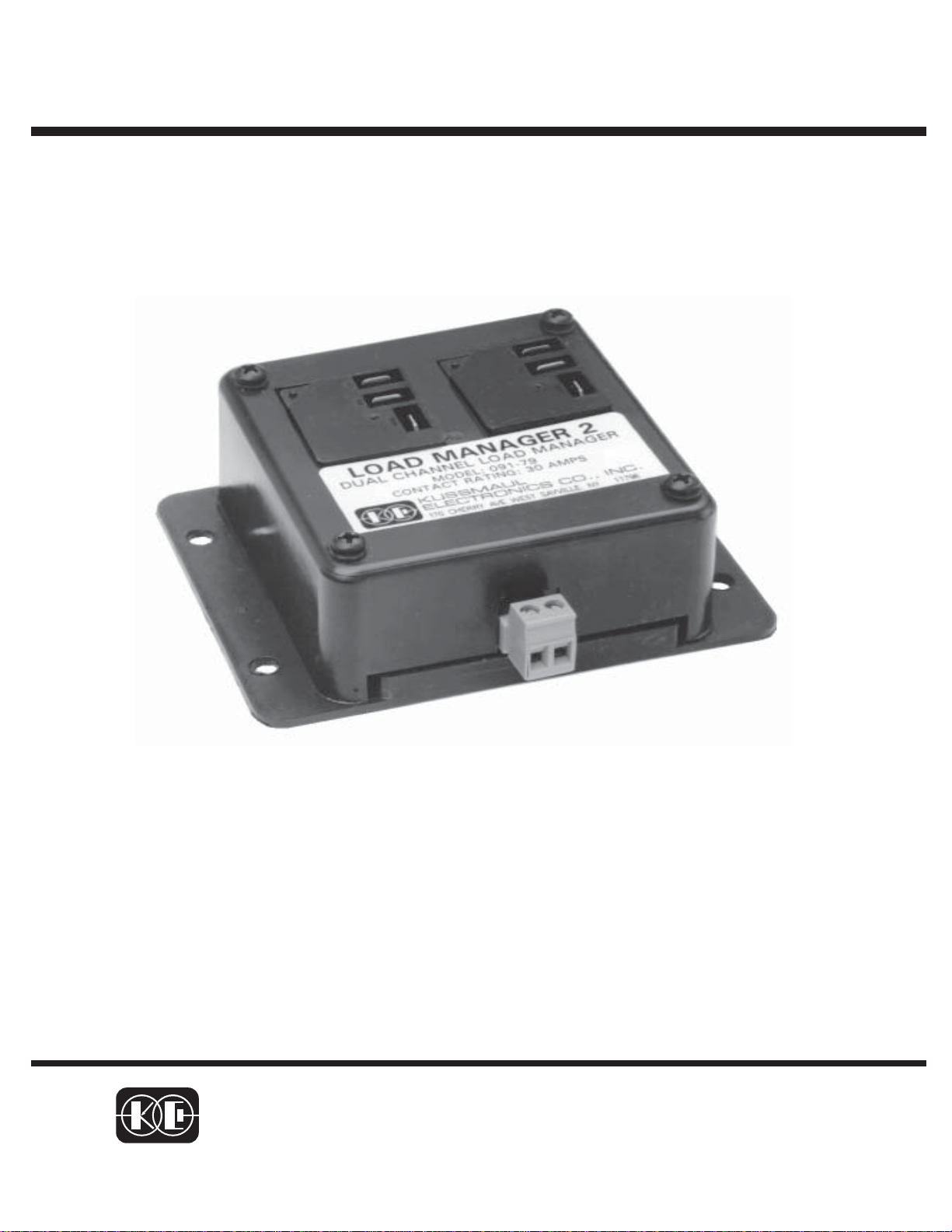
LOAD MANAGER 2
REV. 4/4/02
MODEL #091-79-12
A BATTERY VOLTAGE MONITOR WHICH
DETECTS AN UNDER-VOLTAGE CONDITION
AND HAS TWO OUTPUTS.
3 YEAR WARRANTY
KUSSMAUL ELECTRONICS CO., INC.
170 CHERRY AVE., WEST SAYVILLE, N.Y. 11796
TEL: 631-567-0314 FAX: 631-567-5826 WORLD WIDE WEB: http://www.kussmaul.com E-MAIL: sales@kussmaul.com
Page 2

INTRODUCTION:
The 091-79-12 LOAD MANAGER 2 is a device which continuously monitors the voltage of the
battery. The unit is factory set to actuate at 12.0 volts, but may be field adjusted to other
voltages. Two output relays are provided. One relay is actuated at the 12.0 volt threshold
while the other relay operates when the voltage decreases to 11.50 volts. The output relays
are capable of switching 30 amperes and both “normally open” and “normally closed” contacts
are provided.
INSTALLATION:
Connect the Load Manager 2 to the battery and the loads as illustrated in figure 1. This is a
typical circuit; many other variations are possible. It is important to connect the Bat+ and
Bat- terminals to that point at which the voltage is to be sensed.
ADJUSTMENT:
The factory adjustment for the Load Manager 2 is 12.0 volts for the first relay to be energized.
The 2nd relay is energized at a voltage .5 volts lower than relay 1. No separate adjustment is
provided for relay 2.
To readjust the setpoint, remove the 4 screws and lift off the cover. Connect a variable voltage source to the battery input terminals and an ohmeter across the normally open contacts of
relay 1. Vary the input voltage to the point at which relay 1 just becomes energized. Turn the
trimmer resistor R100 slightly CCW to lower the setpoint or slightly CW to raise the setpoint.
Check the new setting to determine what voltage will cause the relay to be energized.
The circuit responds very slowly so allow ample time, 15 to 30
seconds for the circuit to respond to voltage changes. This time
delay is required to prevent the relay from chattering for small changes
in voltage around the setpoint.
SPECIFICATIONS:
Input Voltage: 10 to 15 volts, D.C.
Input Amps: .020 amps, relay deenergized
Relay Contacts: 30 amperes, max.
Case: non weatherproof, polypropylene
Weight: 8 ounces
CAUTION
.20 amps, relay energized
PAGE2
Page 3

LOAD MANAGER OUTPUT,
WILL BE DE-ENERGIZED WHEN
VOLTAGE GOES BELOW
SETPOINT OF RELAY 2
N.C.
LOAD MANAGER OUTPUT
WILL BE DE-ENERGIZED
WHEN VOLTAGE GOES
BELOW SETPOINT OF
RELAY 1
N.C.
TO LOAD, WILL BE
ENERGIZED WHEN
VOLTAGE GOES BELOW
SETPOINT OF RELAY 2
+12 Volts
N.O.
COM
Fuse
N.O.
COM
Figure 1, Load Manaager 2 Installation
TO LOAD, WILL BE
ENERGIZED WHEN
VOLTAGE GOES BELOW
SETPOINT OF RELAY 1
Fuse
+12 Volts
VOLTAGE
TRIMMER
R100
Figure 2, Voltage Adjustment
PAGE3
12.0 VOLTS
Page 4

INSTALLATION RECORD & WARRANTY
Date Installed
Installed By
Vehicle Identification
Vehicle Owner
WARRANTY
All products of Kussmaul Electronics Company Inc. are warranted to be
free of defects of material or workmanship. Liability is limited to repairing or
replacing at our factory, without charge, any material or defects which
become apparent in normal use within 3 years from the date the equipment
was shipped. Equipment is to be returned, shipping charges prepaid and will
be returned, after repair, shipping charges paid.
Kussmaul Electronics Company, Inc. shall have no liability for damages
of any kind to associated equipment arising from the installation and /or use
of the Kussmaul Electronics Company, Inc. products. The purchaser, by the
acceptance of the equipment, assumes all liability for any damages which
may result from its installation, use or misuse, by the purchaser, his or its
employees or others.
 Loading...