

Page 1
BOOK#091-56-12ac100
4-16-2002
INSTRUCTION MANUAL
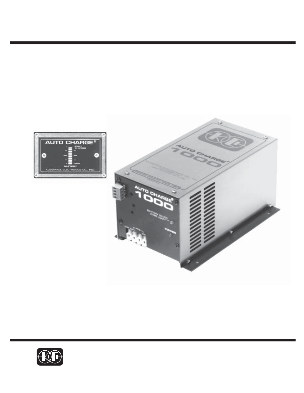
AUTO CHARGE
1000
AUTOMATIC BATTERY CHARGER
MODEL #091-56-12
INPUT :115 volt, 50/60 Hz, 3.5 amps
OUTPUT: 15 AMPERES
3 YEAR WARRANTY
KUSSMAUL ELECTRONICS CO., INC.
170 CHERRY AVE., WEST SAYVILLE, N.Y. 11796
TEL: in NY 631-567-0314 TOLL FREE: 800-346-0857 FAX: 631-567-5826
Page 2

Introduction
The AUTO CHARGE 1000 is a compact, completely automatic, single channel
battery charger designed for vehicles with a single battery system. The charger is
ruggedized to withstand the shock and vibration encountered by vehicle mounted
equipment.
The battery charger features:
• Electronic remote sensing of true battery voltages, eliminates the need
for sensing wires
• Automatic current limiting
• Built-in BATTERY SAVER
• Remote battery charge/condition indicator
• Power “ON” LED indicator
• BATTERY SAVER overload indicator
Charge Controls & Electronic Remote Sensing
The Auto Charge 1000 contains a precision voltage controller to maintain the
battery’s charge. Automatic electronic remote sensing measures the true battery voltage, eliminating the need for the additional sense wires. The output
current of any charger is inherently a series of pulses whose frequency is determined by the power line frequency. Therefore their are brief intervals during
which no charging current flows. During this brief interval the Auto Charge
1000 measures and stores the battery voltage. This battery voltage is compared to a standard and any error is detected and used to control the charger
output at the desired level. Their is no “trickle charge” and therefore no danger
of overcharging and water boil-off.
Automatic Current Limiting
When batteries are severely discharged, some battery chargers can be overloaded due to the high charging current required. The Auto Charge 1000 contains an automatic current limit. This circuit limits the output current to the
rated 15 amperes when charging a deeply discharged battery or if the starter
cranks the engine while charging. The current limiter thus eliminates the need
for an ignition interlock circuit.
Page 3

Battery Saver & Indicator
A 3 ampere BATTERY SAVER is built into the charger. When connected as
shown in the installation wiring diagram, loads on the battery such as radios and
rechargeable hand lights are automatically switched to the BATTERY SAVER
when power is applied to the charger. The BATTERY SAVER allows more efficient
charging by removing these loads. A BATTERY SAVER overload indicator alerts
the operator that the BATTERY SAVER load has exceeded 3 amperes.
WHEN A BATTERY SAVER OVERLOAD OCCURS:
a. Remove the loads for approximately two minutes
b. Reduce the load to 3 amperes or less
c. Reapply the load to the BATTERY SAVER
No fuses are required or provided as the BATTERY SAVER contains an electronic
overload interrupter.
Remote Battery Charge Condition Indicator
This remote indicator shows the charge condition of the battery in 10 levels from
“LOW CHARGE” to “FULLY CHARGED”. This device indicates a defective battery
when a bar graph does not rise to the “FULLY CHARGED” level after an extended
period of charging.
NOTE: If a battery is being discharged with an external load of 1.5 to 4
amperes across it’s terminals, the bar graph may move down 1
or 2 levels. This does not indicate a defective battery.
To avoid this, connect all external loads to the BATTERY SAVER
terminals.
Loads connected to the BATTERY SAVER will be powered either from
the BATTERY SAVER power supply when the A.C. power is “ON”, or
they will be connected to the battery when the A.C. power is “OFF”.
Page 4

Installation Wiring Diagram
AUTO CHARGE
1000
Battery Saver Loads (3 amps max.).
When the charger is disconnect from 120
volts AC the Battery Saver loads automatically are connected to the battery.
WIRE SIZE CHART
CONNECTION ITEM DEFINITION WIRE SIZE
COM
BAT 1
B.S.
BATTERY
COMMON
BATTERY POSITIVE CHARGING LEAD
BATTERY
SAVER
NEGATIVE CHARGING LEAD
FOR CHARGING BATTERIES
AND BATTERY SAVER LOAD
FOR BATTERY
POSITIVE LEAD FOR BATTERY
SAVER LOADS.
14 AWG
14 AWG
16 AWG
IMPORTANT : Wire size is
for a maximum length of 10
feet. If wiring is to be longer,
larger wiring is required. Additional information is available on request.
Page 5

Page 6

Specifications:
Input: 120 volt, 50/60 Hz, 3.5 amperes
Input Fuse: 6 ampere, fast acting
Output: 12 volts D.C. 15 amperes Max.
Remote Sensing: Electronic, sense wires not required
Number of Charger Outputs: 1
Number of Battery Saver Outputs: 1
Battery Saver Output: 12 volts D.C., 3 amperes Max.
Indicators: Power: Red LED, indicates 120 volts power applied
Battery Saver Overload: Yellow LED, indicates Battery Saver
load greater than 3 amperes
Bar Graph: indicates charger output and state of charge of
battery
Weight: 16 lbs
Page 7

INSTALLATION RECORD & WARRANTY
Date Installed
Installed By
Vehicle Identification
Vehicle Owner
WARRANTY
All products of Kussmaul Electronics Company Inc. are warranted to
be free of defects of material or workmanship. Liability is limited to repairing or replacing at our factory, without charge, any material or defects
which become apparent in normal use within 3 years from the date the
equipment was shipped. Equipment is to be returned, shipping charges
prepaid and will be returned, after repair, shipping charges paid.
Kussmaul Electronics Company, Inc. shall have no liability for damages of any kind to associated equipment arising from the installation and
/or use of the Kussmaul Electronics Company, Inc. products. The purchaser, by the acceptance of the equipment, assumes all liability for any
damages which may result from its installation, use or misuse, by the
purchaser, his or its employees or others.
 Loading...